EP1006247B1 - Système de serrure de porte - Google Patents
Système de serrure de porte Download PDFInfo
- Publication number
- EP1006247B1 EP1006247B1 EP99306177A EP99306177A EP1006247B1 EP 1006247 B1 EP1006247 B1 EP 1006247B1 EP 99306177 A EP99306177 A EP 99306177A EP 99306177 A EP99306177 A EP 99306177A EP 1006247 B1 EP1006247 B1 EP 1006247B1
- Authority
- EP
- European Patent Office
- Prior art keywords
- door
- roller unit
- box body
- hook
- fixedly mounted
- Prior art date
- Legal status (The legal status is an assumption and is not a legal conclusion. Google has not performed a legal analysis and makes no representation as to the accuracy of the status listed.)
- Expired - Lifetime
Links
Images


Classifications
-
- H—ELECTRICITY
- H02—GENERATION; CONVERSION OR DISTRIBUTION OF ELECTRIC POWER
- H02B—BOARDS, SUBSTATIONS OR SWITCHING ARRANGEMENTS FOR THE SUPPLY OR DISTRIBUTION OF ELECTRIC POWER
- H02B1/00—Frameworks, boards, panels, desks, casings; Details of substations or switching arrangements
- H02B1/26—Casings; Parts thereof or accessories therefor
- H02B1/30—Cabinet-type casings; Parts thereof or accessories therefor
- H02B1/38—Hinged covers or doors
-
- E—FIXED CONSTRUCTIONS
- E05—LOCKS; KEYS; WINDOW OR DOOR FITTINGS; SAFES
- E05B—LOCKS; ACCESSORIES THEREFOR; HANDCUFFS
- E05B17/00—Accessories in connection with locks
- E05B17/0025—Devices for forcing the wing firmly against its seat or to initiate the opening of the wing
-
- E—FIXED CONSTRUCTIONS
- E05—LOCKS; KEYS; WINDOW OR DOOR FITTINGS; SAFES
- E05C—BOLTS OR FASTENING DEVICES FOR WINGS, SPECIALLY FOR DOORS OR WINDOWS
- E05C9/00—Arrangements of simultaneously actuated bolts or other securing devices at well-separated positions on the same wing
- E05C9/06—Arrangements of simultaneously actuated bolts or other securing devices at well-separated positions on the same wing with three or more sliding bars
- E05C9/063—Arrangements of simultaneously actuated bolts or other securing devices at well-separated positions on the same wing with three or more sliding bars extending along three or more sides of the wing or frame
-
- E—FIXED CONSTRUCTIONS
- E05—LOCKS; KEYS; WINDOW OR DOOR FITTINGS; SAFES
- E05C—BOLTS OR FASTENING DEVICES FOR WINGS, SPECIALLY FOR DOORS OR WINDOWS
- E05C9/00—Arrangements of simultaneously actuated bolts or other securing devices at well-separated positions on the same wing
- E05C9/10—Actuating mechanisms for bars
- E05C9/12—Actuating mechanisms for bars with rack and pinion mechanism
-
- E—FIXED CONSTRUCTIONS
- E05—LOCKS; KEYS; WINDOW OR DOOR FITTINGS; SAFES
- E05C—BOLTS OR FASTENING DEVICES FOR WINGS, SPECIALLY FOR DOORS OR WINDOWS
- E05C9/00—Arrangements of simultaneously actuated bolts or other securing devices at well-separated positions on the same wing
- E05C9/18—Details of fastening means or of fixed retaining means for the ends of bars
- E05C9/1825—Fastening means
- E05C9/1833—Fastening means performing sliding movements
- E05C9/185—Fastening means performing sliding movements parallel with actuating bar
Definitions
- the present invention relates to a door lock system used in boxes and like containers for receiving therein electric instruments, communication instruments and like instruments.
- a plurality of rod members are connected with each other and provided in a peripheral portion of a door; a plurality of hook members are provided in a plurality of portions of the rod members; and, a plurality of roller units are fixedly mounted on a box body, wherein the hook members are engaged with the roller units to draw the roller units aside in closing and locking the door, so that a packing member disposed between the door and the box body is compressed therebetween.
- WO-A-93/20315 discloses a bolt lock, in particular for control-cabinet doors.
- the lock comprises a flat-bar bolt which is mounted to move parallel to the edge of the door, preferably within the arc swing of the door, and which has at least one locking section.
- the lock further comprises a bolt holder, mounted on the door frame and designed to receive and hold the locking section of the bolt.
- the flat-bar bolt is twisted about its longitudinal axis over at least one part of its length in order to form the locking section and is twisted in such a way that the bolt surface in the twisted section is at an angle to the orientation of the bolt and so that a lug in the bolt holder extends out over the locking section at the same angle to the bolt, thus acting as a locking surface.
- a door lock system comprising:
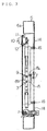
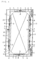
- an embodiment of a door lock system of the present invention comprises: a box body 6 on which a roller unit 7 provided with a rotatable roller element is fixedly mounted; a door 1 on which a roller unit 9 is fixedly mounted; and, a packing member 16 or seal (shown in Fig. 5) disposed between the box body 6 and the door 1.
- a right and a left vertical rod 2 are disposed in the right and the left side of a door 1, respectively.
- an upper and a lower lateral rod 3 are disposed in the upper and the lower side of a door 1, respectively.
- a turning-point transmission unit 4 is fixedly mounted in each of corner portions of the door 1, and provided with a connecting bar 5 through which the vertical rods 2 and the lateral rods 3 are connected with each other to form a chain-like assembly.
- At least one 2 is provided with a rack portion 12 engaging with a pinion gear 11 of a handle member 10.
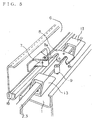
- a hook member 8 is provided with a pair of hook portions 8a, 8b.
- one 8a of the hook portions 8a, 8b of the hook member 8 is engaged with the roller unit 7 of the box body 6 to draw the roller unit 7 aside, and the other 8b of these hook portions 8a, 8b is engaged with a roller unit 9 of the door 1 to draw the roller unit 9 aside.
- the hook member 8 is moved to draw both the roller unit 7 of the box body 6 and the roller unit 9 of the door 1 aside so that the packing member 16 is compressed between the door 1 and the box body 6.
- handle member 10 is of a pull-out rotary type, and is embedded in a front surface of the door 1.
- a rotary shaft provided in a rear-end portion of the handle member 10 is connected with a pinion gear gear 11.
- rack portion 12 is constructed of a series of lateral openings or slots provided in the vertical rod 2 at predetermined intervals corresponding to the pitch of the pinion gear 11.
- the vertical rods 2, lateral rods 3, turning-point transmission units 4 and the connecting bars 5 are connected in series with each other under tension without permitting any slackness.
- the vertical rod 2, which is longer than the lateral rod 3, is inserted into a guide member 13 fixedly mounted on the inner surface of the door 1, so that the vertical rod 2 is limited in idle motion in horizontal plane, i.e. the lateral movement of the vertical rod in the horizontal plane is restricted.
- a flange portion 14 extends around the opening portion of a front wall portion 6a of the box body 6 so as to surround the opening portion.
- the flange portion 14 is constructed of a front concave portion of the box body 6, which concave portion is adjacent to the front wall portion 6a.
- the door 1 assumes a flat box-like shape, which is opened in its inner surface and constructed of: a main front wall portion 1a, an outline of which is substantially the same size as that of an inner surface of the above-mentioned front concave portion of the box body 6; and bent peripheral wall portions 1b contiguous to the individual side portions of the main front wall portion 1a.
- the door 1 is mounted on the box body 6 through two hinge units 15 vertically arranged along the right edge surface of the box body 6, and is supported thereby.
- Adhesively applied and fixed to an end portion of the flange portion 14 is a packing 16 made of rubber. It is also possible to provide the packing 16 in the side of the door 1 alternatively or additionally.
- Each of the box body 6 and the door 1 is constructed of steel plates.
- the hook member 8 in closing the door 1, it is possible for the hook member 8 to have its hook portions 8a and 8b engaged with the roller unit 7 of the box body 6 and the roller unit 9 of the door 1, respectively, to draw these roller units 7, 9 aside, so that the packing 16 is substantially uniformly compressed over its entire length between the box body 6 and the door 1.
- the hook members 8 supported by the vertical rods 2 and the lateral rods 3 it is also possible to directly support the hook members 8 by the door 1.
- the above construction of the present invention ensures that the interior space of the box body 6 is excellent in gas-tight and water-tight properties when closed by the door 1.
- the hook member 8 is center-balanced by its hook portions 8a, 8b, so that shearing forces to which the vertical rods 2 and the lateral rods 3 are subjected are lessened. Consequently, it is possible to sufficiently lock the door 1 without causing any flexing of the vertical rods 2 and the lateral rods 3 and also without any fear that the hook members 8 are subjected to shearing forces and cause flexing.
Landscapes
- Engineering & Computer Science (AREA)
- Mechanical Engineering (AREA)
- Power Engineering (AREA)
- Specific Sealing Or Ventilating Devices For Doors And Windows (AREA)
- Casings For Electric Apparatus (AREA)
- Regulating Braking Force (AREA)
- Apparatus For Radiation Diagnosis (AREA)
- Vehicle Body Suspensions (AREA)
- Lock And Its Accessories (AREA)
Claims (1)
- Système de verrouillage de porte comprenant :un corps de boítier (6) sur lequel une unité à rouleau (7) est montée de manière fixe;une porte (1) sur laquelle une unité à rouleau (9) est montée de manière fixe;un membre de garnissage disposé entre ledit corps de boítier (6) et ladite porte (1);une tige verticale droite et une gauche (2) disposées du côté droit et du côté gauche de ladite porte (1), respectivement, au moins une desdites tiges verticales (2) étant pourvue d'une partie à crémaillère (12) engageant un engrenage à pignon (11) d'un membre de poignée (10);une tige latérale supérieure et une inférieure (3) disposées du côté supérieur et du côté inférieur de ladite porte (1), respectivement;une unité de transmission de point tournant (4), qui est montée de manière fixe dans chacune des parties de coin de ladite porte (1) et pourvue d'une barre de liaison (5) par laquelle lesdites tiges verticales (2) et lesdites tiges latérales (3) sont connectées l'une à l'autre pour former un ensemble genre chaíne; etun membre de crochet (8) pourvu d'une paire de parties à crochet (8a, 8b), dont l'une (8a) est engagée avec ladite unité à rouleau (7) dudit corps de boítier (6) pour tirer ladite unité de côté (7), et dont l'autre (8) est engagée avec ladite unité à rouleau (9) de ladite porte (1) pour tirer ladite unité à rouleau (9) de côté dans une opération de fermeture de ladite porte (1);où, lorsque ledit membre de poignée est sorti et tourné, ledit membre de crochet (8) est déplacé pour tirer ladite unité à rouleau (7) dudit corps de boítier (6) et ladite unité à rouleau (9) de ladite porte (1) de côté de sorte que le membre de garnissage (16) est comprimé entre ladite porte (1) et ledit corps de boítier (6).
Applications Claiming Priority (2)
| Application Number | Priority Date | Filing Date | Title |
|---|---|---|---|
| JP10343696A JP2983979B1 (ja) | 1998-12-03 | 1998-12-03 | 扉用締付けロック装置 |
| JP34369698 | 1998-12-03 |
Publications (2)
| Publication Number | Publication Date |
|---|---|
| EP1006247A1 EP1006247A1 (fr) | 2000-06-07 |
| EP1006247B1 true EP1006247B1 (fr) | 2001-10-24 |
Family
ID=18363556
Family Applications (1)
| Application Number | Title | Priority Date | Filing Date |
|---|---|---|---|
| EP99306177A Expired - Lifetime EP1006247B1 (fr) | 1998-12-03 | 1999-08-03 | Système de serrure de porte |
Country Status (4)
| Country | Link |
|---|---|
| EP (1) | EP1006247B1 (fr) |
| JP (1) | JP2983979B1 (fr) |
| AT (1) | ATE207572T1 (fr) |
| DE (1) | DE69900386T2 (fr) |
Cited By (2)
| Publication number | Priority date | Publication date | Assignee | Title |
|---|---|---|---|---|
| US8161601B2 (en) | 2005-12-09 | 2012-04-24 | Industrilas Ab | Hinge and latch mechanism |
| CN101379256B (zh) * | 2005-12-09 | 2012-05-09 | 工业公司 | 滚轮控制机构致动装置 |
Families Citing this family (5)
| Publication number | Priority date | Publication date | Assignee | Title |
|---|---|---|---|---|
| JP3281343B2 (ja) | 1999-10-26 | 2002-05-13 | 埼玉日本電気株式会社 | 扉全周締め込み構造 |
| DE102005019209B4 (de) * | 2005-04-25 | 2007-07-12 | Dura Automotive Plettenberg Entwicklungs- Und Vertriebs Gmbh | Schließeinrichtung für Türen oder Klappen von Kraftfahrzeugen |
| JP4732388B2 (ja) * | 2007-03-22 | 2011-07-27 | 株式会社日立製作所 | 電子機器筐体構造 |
| JP5334610B2 (ja) * | 2009-02-03 | 2013-11-06 | 株式会社クボタ | 空気調和機 |
| CN111769456A (zh) * | 2020-07-31 | 2020-10-13 | 江苏永特电力科技有限公司 | 一种动态无功补偿电容器柜 |
Family Cites Families (4)
| Publication number | Priority date | Publication date | Assignee | Title |
|---|---|---|---|---|
| DE3672149D1 (de) * | 1986-09-25 | 1990-07-26 | Dieter Ramsauer | Stangenverschluss mit von der stange getragenen verriegelungszapfen, insbesondere doppelrollzapfen. |
| DE4210586C2 (de) * | 1992-03-31 | 1994-04-14 | Emka Beschlagteile | Stangenverriegelung für Türen, insgbesondere für Schaltschranktüren |
| JP2700444B2 (ja) | 1995-01-26 | 1998-01-21 | タキゲン製造株式会社 | 電気機器設置用箱体の扉用ロック装置 |
| EP0847121A1 (fr) * | 1996-12-09 | 1998-06-10 | Barat S.A. | Armoire étanche escamotable pour réseau urbain d'alimentation en énergie électrique |
-
1998
- 1998-12-03 JP JP10343696A patent/JP2983979B1/ja not_active Expired - Lifetime
-
1999
- 1999-08-03 AT AT99306177T patent/ATE207572T1/de not_active IP Right Cessation
- 1999-08-03 EP EP99306177A patent/EP1006247B1/fr not_active Expired - Lifetime
- 1999-08-03 DE DE69900386T patent/DE69900386T2/de not_active Expired - Lifetime
Cited By (3)
| Publication number | Priority date | Publication date | Assignee | Title |
|---|---|---|---|---|
| US8161601B2 (en) | 2005-12-09 | 2012-04-24 | Industrilas Ab | Hinge and latch mechanism |
| CN101379256B (zh) * | 2005-12-09 | 2012-05-09 | 工业公司 | 滚轮控制机构致动装置 |
| US8226130B2 (en) | 2005-12-09 | 2012-07-24 | Industrilås i NässjöAB | Control roller mechanism-activator |
Also Published As
| Publication number | Publication date |
|---|---|
| JP2000170457A (ja) | 2000-06-20 |
| JP2983979B1 (ja) | 1999-11-29 |
| DE69900386D1 (de) | 2001-11-29 |
| EP1006247A1 (fr) | 2000-06-07 |
| DE69900386T2 (de) | 2002-06-13 |
| ATE207572T1 (de) | 2001-11-15 |
Similar Documents
| Publication | Publication Date | Title |
|---|---|---|
| EP1006247B1 (fr) | Système de serrure de porte | |
| DE19955883A1 (de) | Kraftfahrzeugtürverschluss | |
| EP2086726B1 (fr) | Machine-outil à main avec une poignée amortie des vibrations et pourvue d'un commutateur | |
| US20060196120A1 (en) | Dual-opening mechanism of door | |
| US5102174A (en) | Gearing for espagnolette fitting | |
| WO1994015050A1 (fr) | Dispositif de fermeture pour portes de boitiers ou d'armoires | |
| DE102010029065A1 (de) | Türkantenschutzeinrichtung | |
| CN105927063B (zh) | 能够近控和遥控的车门锁 | |
| GB2285481A (en) | Apparatus mounting a latch device to a sliding door | |
| EP1165921B1 (fr) | Dispositif de commande de porte ou de fenetre a chaine double | |
| RU98116453A (ru) | Окно, дверь или другое подобное изделие с фурнитурной системой | |
| EP3994323A1 (fr) | Verrou en u portable | |
| US6035674A (en) | Door locking device with several closing rods | |
| EP1010847B1 (fr) | Conteneur avec une porte susceptible d'être ouvert a 270 degres | |
| EP1340872B1 (fr) | Dispositif de verrouillage | |
| EP3036168B1 (fr) | Revetement de machines rotatifs avec des modules peripheriques | |
| EP1707719B1 (fr) | Ensemble d'entraînement pour cadres de fenêtre et de porte | |
| EP0270839B1 (fr) | Dispositif de fermeture et verrouillage en particulier pour portes de fourgons, réservoirs et similaires | |
| DE20120604U1 (de) | Antriebseinrichtung zum Bewegen eines Flügels eines Fensters | |
| EP1810785A1 (fr) | Dispositif de serrage coulissant | |
| GB2337073A (en) | Shootbolt assembly with transmission members which are in tension during locking | |
| KR102808852B1 (ko) | 쇼케이스의 도어개폐장치 | |
| CN210033160U (zh) | 一种加固型不锈钢防盗门 | |
| GB2260362A (en) | Espagnolette | |
| SU1387084A2 (ru) | Шкаф электроустановок |
Legal Events
| Date | Code | Title | Description |
|---|---|---|---|
| PUAI | Public reference made under article 153(3) epc to a published international application that has entered the european phase |
Free format text: ORIGINAL CODE: 0009012 |
|
| AK | Designated contracting states |
Kind code of ref document: A1 Designated state(s): AT BE CH CY DE DK ES FI FR GB GR IE IT LI LU MC NL PT SE |
|
| AX | Request for extension of the european patent |
Free format text: AL;LT;LV;MK;RO;SI |
|
| 17P | Request for examination filed |
Effective date: 20000704 |
|
| 17Q | First examination report despatched |
Effective date: 20000929 |
|
| AKX | Designation fees paid |
Free format text: AT BE CH CY DE DK ES FI FR GB GR IE IT LI LU MC NL PT SE |
|
| GRAG | Despatch of communication of intention to grant |
Free format text: ORIGINAL CODE: EPIDOS AGRA |
|
| GRAG | Despatch of communication of intention to grant |
Free format text: ORIGINAL CODE: EPIDOS AGRA |
|
| GRAH | Despatch of communication of intention to grant a patent |
Free format text: ORIGINAL CODE: EPIDOS IGRA |
|
| GRAH | Despatch of communication of intention to grant a patent |
Free format text: ORIGINAL CODE: EPIDOS IGRA |
|
| GRAA | (expected) grant |
Free format text: ORIGINAL CODE: 0009210 |
|
| ITF | It: translation for a ep patent filed | ||
| AK | Designated contracting states |
Kind code of ref document: B1 Designated state(s): AT BE CH CY DE DK ES FI FR GB GR IE IT LI LU MC NL PT SE |
|
| PG25 | Lapsed in a contracting state [announced via postgrant information from national office to epo] |
Ref country code: NL Free format text: LAPSE BECAUSE OF FAILURE TO SUBMIT A TRANSLATION OF THE DESCRIPTION OR TO PAY THE FEE WITHIN THE PRESCRIBED TIME-LIMIT Effective date: 20011024 Ref country code: LI Free format text: LAPSE BECAUSE OF FAILURE TO SUBMIT A TRANSLATION OF THE DESCRIPTION OR TO PAY THE FEE WITHIN THE PRESCRIBED TIME-LIMIT Effective date: 20011024 Ref country code: FI Free format text: LAPSE BECAUSE OF FAILURE TO SUBMIT A TRANSLATION OF THE DESCRIPTION OR TO PAY THE FEE WITHIN THE PRESCRIBED TIME-LIMIT Effective date: 20011024 Ref country code: CH Free format text: LAPSE BECAUSE OF FAILURE TO SUBMIT A TRANSLATION OF THE DESCRIPTION OR TO PAY THE FEE WITHIN THE PRESCRIBED TIME-LIMIT Effective date: 20011024 Ref country code: BE Free format text: LAPSE BECAUSE OF FAILURE TO SUBMIT A TRANSLATION OF THE DESCRIPTION OR TO PAY THE FEE WITHIN THE PRESCRIBED TIME-LIMIT Effective date: 20011024 Ref country code: AT Free format text: LAPSE BECAUSE OF FAILURE TO SUBMIT A TRANSLATION OF THE DESCRIPTION OR TO PAY THE FEE WITHIN THE PRESCRIBED TIME-LIMIT Effective date: 20011024 |
|
| REF | Corresponds to: |
Ref document number: 207572 Country of ref document: AT Date of ref document: 20011115 Kind code of ref document: T |
|
| REG | Reference to a national code |
Ref country code: CH Ref legal event code: EP |
|
| REG | Reference to a national code |
Ref country code: IE Ref legal event code: FG4D |
|
| REF | Corresponds to: |
Ref document number: 69900386 Country of ref document: DE Date of ref document: 20011129 |
|
| REG | Reference to a national code |
Ref country code: GB Ref legal event code: IF02 |
|
| PG25 | Lapsed in a contracting state [announced via postgrant information from national office to epo] |
Ref country code: SE Free format text: LAPSE BECAUSE OF FAILURE TO SUBMIT A TRANSLATION OF THE DESCRIPTION OR TO PAY THE FEE WITHIN THE PRESCRIBED TIME-LIMIT Effective date: 20020124 Ref country code: PT Free format text: LAPSE BECAUSE OF FAILURE TO SUBMIT A TRANSLATION OF THE DESCRIPTION OR TO PAY THE FEE WITHIN THE PRESCRIBED TIME-LIMIT Effective date: 20020124 Ref country code: DK Free format text: LAPSE BECAUSE OF FAILURE TO SUBMIT A TRANSLATION OF THE DESCRIPTION OR TO PAY THE FEE WITHIN THE PRESCRIBED TIME-LIMIT Effective date: 20020124 |
|
| PG25 | Lapsed in a contracting state [announced via postgrant information from national office to epo] |
Ref country code: GR Free format text: LAPSE BECAUSE OF FAILURE TO SUBMIT A TRANSLATION OF THE DESCRIPTION OR TO PAY THE FEE WITHIN THE PRESCRIBED TIME-LIMIT Effective date: 20020125 |
|
| NLV1 | Nl: lapsed or annulled due to failure to fulfill the requirements of art. 29p and 29m of the patents act | ||
| ET | Fr: translation filed | ||
| PG25 | Lapsed in a contracting state [announced via postgrant information from national office to epo] |
Ref country code: ES Free format text: LAPSE BECAUSE OF FAILURE TO SUBMIT A TRANSLATION OF THE DESCRIPTION OR TO PAY THE FEE WITHIN THE PRESCRIBED TIME-LIMIT Effective date: 20020430 |
|
| REG | Reference to a national code |
Ref country code: CH Ref legal event code: PL |
|
| PG25 | Lapsed in a contracting state [announced via postgrant information from national office to epo] |
Ref country code: LU Free format text: LAPSE BECAUSE OF NON-PAYMENT OF DUE FEES Effective date: 20020803 |
|
| PG25 | Lapsed in a contracting state [announced via postgrant information from national office to epo] |
Ref country code: IE Free format text: LAPSE BECAUSE OF NON-PAYMENT OF DUE FEES Effective date: 20020805 |
|
| PLBE | No opposition filed within time limit |
Free format text: ORIGINAL CODE: 0009261 |
|
| STAA | Information on the status of an ep patent application or granted ep patent |
Free format text: STATUS: NO OPPOSITION FILED WITHIN TIME LIMIT |
|
| PG25 | Lapsed in a contracting state [announced via postgrant information from national office to epo] |
Ref country code: CY Free format text: LAPSE BECAUSE OF FAILURE TO SUBMIT A TRANSLATION OF THE DESCRIPTION OR TO PAY THE FEE WITHIN THE PRESCRIBED TIME-LIMIT Effective date: 20020831 |
|
| 26N | No opposition filed | ||
| PG25 | Lapsed in a contracting state [announced via postgrant information from national office to epo] |
Ref country code: MC Free format text: LAPSE BECAUSE OF NON-PAYMENT OF DUE FEES Effective date: 20030301 |
|
| REG | Reference to a national code |
Ref country code: IE Ref legal event code: MM4A |
|
| PGFP | Annual fee paid to national office [announced via postgrant information from national office to epo] |
Ref country code: DE Payment date: 20130731 Year of fee payment: 15 |
|
| REG | Reference to a national code |
Ref country code: DE Ref legal event code: R119 Ref document number: 69900386 Country of ref document: DE |
|
| REG | Reference to a national code |
Ref country code: DE Ref legal event code: R119 Ref document number: 69900386 Country of ref document: DE Effective date: 20150303 |
|
| REG | Reference to a national code |
Ref country code: FR Ref legal event code: PLFP Year of fee payment: 17 |
|
| PG25 | Lapsed in a contracting state [announced via postgrant information from national office to epo] |
Ref country code: DE Free format text: LAPSE BECAUSE OF NON-PAYMENT OF DUE FEES Effective date: 20150303 |
|
| PGFP | Annual fee paid to national office [announced via postgrant information from national office to epo] |
Ref country code: FR Payment date: 20150629 Year of fee payment: 17 |
|
| PGFP | Annual fee paid to national office [announced via postgrant information from national office to epo] |
Ref country code: IT Payment date: 20150827 Year of fee payment: 17 |
|
| PGFP | Annual fee paid to national office [announced via postgrant information from national office to epo] |
Ref country code: GB Payment date: 20160803 Year of fee payment: 18 |
|
| REG | Reference to a national code |
Ref country code: FR Ref legal event code: ST Effective date: 20170428 |
|
| PG25 | Lapsed in a contracting state [announced via postgrant information from national office to epo] |
Ref country code: FR Free format text: LAPSE BECAUSE OF NON-PAYMENT OF DUE FEES Effective date: 20160831 |
|
| PG25 | Lapsed in a contracting state [announced via postgrant information from national office to epo] |
Ref country code: IT Free format text: LAPSE BECAUSE OF NON-PAYMENT OF DUE FEES Effective date: 20160803 |
|
| GBPC | Gb: european patent ceased through non-payment of renewal fee |
Effective date: 20170803 |
|
| PG25 | Lapsed in a contracting state [announced via postgrant information from national office to epo] |
Ref country code: GB Free format text: LAPSE BECAUSE OF NON-PAYMENT OF DUE FEES Effective date: 20170803 |