EP1006259A2 - Bohrlochwerkzeug - Google Patents
Bohrlochwerkzeug Download PDFInfo
- Publication number
- EP1006259A2 EP1006259A2 EP99309270A EP99309270A EP1006259A2 EP 1006259 A2 EP1006259 A2 EP 1006259A2 EP 99309270 A EP99309270 A EP 99309270A EP 99309270 A EP99309270 A EP 99309270A EP 1006259 A2 EP1006259 A2 EP 1006259A2
- Authority
- EP
- European Patent Office
- Prior art keywords
- piston
- valve
- housing
- pressure
- movable
- Prior art date
- Legal status (The legal status is an assumption and is not a legal conclusion. Google has not performed a legal analysis and makes no representation as to the accuracy of the status listed.)
- Withdrawn
Links
Images




Classifications
-
- E—FIXED CONSTRUCTIONS
- E21—EARTH OR ROCK DRILLING; MINING
- E21B—EARTH OR ROCK DRILLING; OBTAINING OIL, GAS, WATER, SOLUBLE OR MELTABLE MATERIALS OR A SLURRY OF MINERALS FROM WELLS
- E21B34/00—Valve arrangements for boreholes or wells
- E21B34/06—Valve arrangements for boreholes or wells in wells
- E21B34/10—Valve arrangements for boreholes or wells in wells operated by control fluid supplied from outside the borehole
-
- E—FIXED CONSTRUCTIONS
- E21—EARTH OR ROCK DRILLING; MINING
- E21B—EARTH OR ROCK DRILLING; OBTAINING OIL, GAS, WATER, SOLUBLE OR MELTABLE MATERIALS OR A SLURRY OF MINERALS FROM WELLS
- E21B2200/00—Special features related to earth drilling for obtaining oil, gas or water
- E21B2200/05—Flapper valves
Definitions
- the present invention relates to a downhole tool such as a subsurface safety valve and, more particularly, to a downhole tool utilising opposed pistons. More specifically, the invention relates to a subsurface safety valve having a tubular housing and an axially shiftable flow tube used to manipulate a valve closure member.
- Subsurface safety valves are used within well bores to prevent the uncontrolled escape of well bore fluids, which if not controlled could directly lead to a catastrophic well blowout.
- Certain styles of safety valves are called flapper type valves because the valve closure member is in the form of a circular disc or in the form of a curved disc. These flappers can be opened by the application of hydraulic pressure to a piston and cylinder assembly to move an opening prong against the flapper. The opening prong is biased by a helical spring in a direction to allow the flapper to close in the event that hydraulic fluid pressure is reduced or lost.
- FIGS 1a and 1b illustrate a standard safety valve configuration wherein a safety valve 10 is interposed in a tubing string 12.
- a control line 16 is used to open the valve.
- the valve 10 includes a tubular valve housing 14 with an axial passage 20.
- the opening prong 30 engages the closure member 32 and pushes the member into an open position.
- a spring 28 opposes the motion of the piston so that when the hydraulic pressure is released, the piston and opening prong 30 are returned to a first position.
- Pressure closing Force spring /Area piston Setting subsurface safety valves deeper is typically just a matter of ensuring sufficient closing pressure to offset the hydrostatic pressure acting to cause the valve to stay open. Increasing closing pressure is accomplished by increasing the Force spring term or decreasing the Area piston term.
- the umbilical line used to deliver the hydraulic pressure can limit the available surface operating pressure.
- the valve requires changes in the spring force or piston area in accordance with the above formulas, thus requiring customization of the valve depending on the depth at which it will be placed. Design considerations of the well, string, and tools involved can also make such valve designs impractical at lower well depths.
- a balance line valve 40 having a piston 48 in a housing 42 is illustrated in Figure 2.
- Two hydraulic chambers are pressurized on opposite sides of the piston 48.
- a control line is coupled to a first port 44 while the balance line is coupled to a second port 46.
- Each hydraulic line is filled with the same type of fluid. Hydrostatic pressure above and below the piston is equal. Thus, there is no downward force on the spring as a result of the hydrostatic pressure.
- the valve is operated by pressurizing the upper chamber. This increases the downward force, displacing fluid from the lower chamber and compressing the spring 50 to open the valve.
- Well pressure only has access to the seal diameters with cross sectional areas A and A'.
- FIG. 3 Another style of balance line safety valve is illustrated in Figure 3.
- the valve 60 has a piston 64 captured within a housing 62 and three hydraulic chambers 68, 70, and 72, two above and one below the valve piston 64.
- Two control lines are run to the surface.
- Well pressure acts on seals 74, 80. Since the piston areas A and A' are the same, well pressure has no influence on the pressure required to displace the piston.
- Control line and balance line hydrostatic pressures act on identical piston areas B-A' and B-A", so there is no net upward or downward force. If seal 74 leaks, well pressure accesses the balance line system. This pressure acts on area B-A", boosting force F3, which with F2 will overcome F1, to close the valve. If seal 76 leaks, communication between the control and balance lines will be established.
- F1 will always equal F3.
- F2 will be the only active force causing the valve to close.
- seal 78 leaks, it has the same effect as seal 76 leaking.
- seal 80 leaks, tubing pressure accesses the balance line system. This pressure acts to increase F3, overcoming F1 and closing the valve.
- Control line force F1 is greater than the tubing assisted balance force F3 with the spring force F2. In all modes of failure for this valve, the valve fails permanently to a closed position.
- a dome charge safety valve uses a captured gas charge.
- the gas charge provides a heavy spring force to achieve an increased closing pressure.
- dome charge designs are complex and require specialized manufacturing and personnel. This increases the cost and decreases the reliability of the design because numerous seals are required. Also, industry standards favour metal-to-metal (MTM) sealing systems. Gas charges require the use of elastomeric seals.
- a balance line SSSV should incorporate the benefits of a balance line SSSV.
- Such a design should utilize a metal-to-metal sealing system for increased reliability and also allow for the application of balance line pressure to cycle the valve's flow tube, thus opening the valve. Further, the design should minimize operational friction to reduce the required spring force to close the valve.
- the present invention relates to an improved method of actuating a downhole safety valve that uses a pair of opposed pistons connected to individual control lines that are run to the surface.
- the hydrostatic pressure in the control line and balance line affects both pistons equally, thereby cancelling out any net affect.
- the pistons are situated in the valve housing so that one will tend to ascend in reaction to the hydrostatic pressure, while the other piston will tend to descend. Both are coupled to a common axially movable member within the valve.
- the control line attached to the first piston is pressurized.
- the increased pressure forces the piston downward until it rests against a downstop.
- the distal end of the piston is attached to an axially movable flow tube that pushes through the closure member of the valve thereby opening the valve's central passage.
- a compression spring opposes the motion of the piston. Therefore, when the opening pressure subsides, the compression spring will return the flow tube to its original position, allowing the closure member to close.
- a downhole tool having an element movable by a piston force between a first and second position comprising a valve housing, a first piston movable within the housing, and a second piston movable within the housing, wherein the first and second pistons are coupled to each other.
- the downhole tool further comprises a valve closure member captured in the housing and movable between an open and closed position, and axially shiftable flow tube captured in the housing for opening the valve closure member.
- a safety valve for use in a well comprising a valve housing, a first piston movable within the housing, a second piston movable within the housing, the first and second pistons being coupled to each other, a valve closure member captured in the housing and movable between an open and closed position, and an axially shiftable flow tube captured in the housing for opening the valve closure member.
- the first piston is coupled to a control line and/or the second piston is coupled to a balance line.
- the downhole tool or safety valve further comprises a spring within the housing and opposing the motion of the axially shiftable flow tube.
- first and second pistons are coupled to a movable member.
- the downhole tool or safety valve further comprises first and second control lines coupled to a surface pressure source.
- valve housing comprises a first and second piston chamber for capturing the first and second pistons, and the control line and balance line are coupled to the valve housing to move the pistons in opposite directions.
- the valve housing comprises a first and second piston chamber for capturing the first and second pistons, and a hydrostatic pressure is applied by the balance line to the second piston which is substantially equal and offsetting to a hydrostatic pressure applied by the control line to the first piston.
- a method of operating a downhole tool placed in the flow path of a well tubing string within a well comprising the steps of coupling a control line to a first piston chamber having a first piston, coupling a balance line to a second piston chamber having a second piston, and coupling both the first and second pistons to a movable member.
- the method further comprises supplying a substantially equal hydrostatic pressure through both the control line and the balance line.
- the method further comprises supplying a sufficient pressure through the control line to move the first piston downward.
- the method further comprises overcoming an opposing spring force, and forcing an opening prong through a closure member.
- the present invention allows for the isolation of the valve from effects of hydrostatic pressure and wellbore pressure. It also provides a method of positively closing the valve in the event of a failure.
- the present invention preferably also uses metal-to-metal and non-elastomeric sealing.
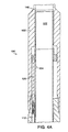
- FIGS. 4a, 4b and 4c provide partial sectional views along the length of a safety valve 100 that embodies the present invention.
- the safety valve 100 has an outer tubular housing that defines a central passage 122.
- the outer housing can be constructed of several sections 102, 104, 106, and 108. Each section can be coupled by threaded connection during the construction of the valve 100.
- the housing defines a number of inner structures, including piston chambers 110 and 112.
- the piston chamber 110 is coupled to control line 114, while piston chamber 112 is coupled to balance line 116. Both the control line and the balance line can be coupled to a surface pressure source.
- the weight of the hydraulic fluid in the control line and the balance line produces a hydrostatic force within the chambers 110, 112.
- Pistons 118 and 120 are captured in chambers 110, 112 respectively.
- the hydraulic fluid in the control line and the balance line should exert a substantially equal and offsetting force on the pistons.
- To open the valve only control line 114 is pressurized.
- piston 118 moves downward compressing spring 128.
- the piston simultaneously acts on movable member 124 and opening prong 130.
- the pistons are both coupled to the movable member 124.
- piston 120 also descends in chamber 112.
- the distal end 130a of the opening prong 130 contacts the closure member 132 of the valve.
- the closure member 132 is hinged at 134, allowing it to pivot to an open position.
- the piston 118 can travel between upstop 140 and downstop 142.
- Figures 5a, 5b, and 5c illustrate the closure member in the open position. Note that the spring 128 is shown in a compressed state. The closure member 132 is in an open position, allowing well fluids to pass through the central passage of the valve. The distal end 130a of the opening prong rests against a stop 136. In the event that the safety valve becomes stuck in an open state, pressure can be applied to the balance line 116, thus moving piston 120 upward in chamber 112. The movable member 124 and piston 118 also move upward in conjunction with the piston 120. The ability to cycle the motion of the valve through the use of the balance line is an improvement over prior art valves.
- the invention described above may be modified.
- the invention is applicable not only to tubing conveyed safety valves, but also to wireline-conveyed safety valves, sliding side door devices, and other downhole tools that are movable.
Landscapes
- Life Sciences & Earth Sciences (AREA)
- Engineering & Computer Science (AREA)
- Geology (AREA)
- Mining & Mineral Resources (AREA)
- Physics & Mathematics (AREA)
- Environmental & Geological Engineering (AREA)
- Fluid Mechanics (AREA)
- General Life Sciences & Earth Sciences (AREA)
- Geochemistry & Mineralogy (AREA)
- Safety Valves (AREA)
Applications Claiming Priority (2)
| Application Number | Priority Date | Filing Date | Title |
|---|---|---|---|
| US204103 | 1998-12-01 | ||
| US09/204,103 US20020074129A1 (en) | 1998-12-01 | 1998-12-01 | Downhole tool utilizing opposed pistons |
Publications (1)
| Publication Number | Publication Date |
|---|---|
| EP1006259A2 true EP1006259A2 (de) | 2000-06-07 |
Family
ID=22756633
Family Applications (1)
| Application Number | Title | Priority Date | Filing Date |
|---|---|---|---|
| EP99309270A Withdrawn EP1006259A2 (de) | 1998-12-01 | 1999-11-22 | Bohrlochwerkzeug |
Country Status (2)
| Country | Link |
|---|---|
| US (1) | US20020074129A1 (de) |
| EP (1) | EP1006259A2 (de) |
Cited By (5)
| Publication number | Priority date | Publication date | Assignee | Title |
|---|---|---|---|---|
| GB2399113B (en) * | 2002-05-03 | 2006-02-22 | Weatherford Lamb | Subsurface value with system and method for sealing |
| US7392849B2 (en) * | 2005-03-01 | 2008-07-01 | Weatherford/Lamb, Inc. | Balance line safety valve with tubing pressure assist |
| GB2418939B (en) * | 2004-10-11 | 2009-06-24 | Schlumberger Holdings | Downhole safety valve assembly having sensing capabilities |
| US8640769B2 (en) | 2011-09-07 | 2014-02-04 | Weatherford/Lamb, Inc. | Multiple control line assembly for downhole equipment |
| US9771769B2 (en) | 2014-04-28 | 2017-09-26 | Owen Oil Tools Lp | Devices and related methods for actuating wellbore tools with a pressurized gas |
Families Citing this family (16)
| Publication number | Priority date | Publication date | Assignee | Title |
|---|---|---|---|---|
| US6691785B2 (en) * | 2000-08-29 | 2004-02-17 | Schlumberger Technology Corporation | Isolation valve |
| US6988556B2 (en) * | 2002-02-19 | 2006-01-24 | Halliburton Energy Services, Inc. | Deep set safety valve |
| US7455114B2 (en) | 2005-01-25 | 2008-11-25 | Schlumberger Technology Corporation | Snorkel device for flow control |
| US8418758B2 (en) * | 2009-08-04 | 2013-04-16 | Impact Selector, Inc. | Jarring tool with micro adjustment |
| US9010448B2 (en) | 2011-04-12 | 2015-04-21 | Halliburton Energy Services, Inc. | Safety valve with electrical actuator and tubing pressure balancing |
| US8816689B2 (en) * | 2011-05-17 | 2014-08-26 | Saudi Arabian Oil Company | Apparatus and method for multi-component wellbore electric field Measurements using capacitive sensors |
| CN103930647B (zh) * | 2011-11-08 | 2017-11-17 | 国际壳牌研究有限公司 | 用于烃井的阀,设置有该阀的烃井以及该阀的应用 |
| WO2013120837A1 (en) | 2012-02-14 | 2013-08-22 | Shell Internationale Research Maatschappij B.V. | Method for producing hydrocarbon gas from a wellbore and valve assembly |
| US9133688B2 (en) * | 2012-08-03 | 2015-09-15 | Tejas Research & Engineering, Llc | Integral multiple stage safety valves |
| US9598931B2 (en) * | 2014-06-24 | 2017-03-21 | Halliburton Energy Services Inc. | Multi-acting downhole tool arrangement |
| US10472929B2 (en) * | 2017-01-25 | 2019-11-12 | Baker Hughes, A Ge Company, Llc | Tubular isolation valve resettable lock open mechanism |
| US11015418B2 (en) * | 2018-06-06 | 2021-05-25 | Baker Hughes, A Ge Company, Llc | Tubing pressure insensitive failsafe wireline retrievable safety valve |
| US10920529B2 (en) | 2018-12-13 | 2021-02-16 | Tejas Research & Engineering, Llc | Surface controlled wireline retrievable safety valve |
| AU2021420723A1 (en) | 2021-01-14 | 2023-07-27 | Schlumberger Technology B.V. | Wellbore pressure insensitive hydraulic piston configuration |
| US12385355B1 (en) * | 2024-03-20 | 2025-08-12 | Halliburton Energy Services, Inc. | Deep set wireline retrievable safety valve |
| US12680419B2 (en) | 2025-01-06 | 2026-07-14 | Halliburton Energy Services, Inc. | High flow, tubing insensitive, deep set wireline retrievable safety valve |
-
1998
- 1998-12-01 US US09/204,103 patent/US20020074129A1/en not_active Abandoned
-
1999
- 1999-11-22 EP EP99309270A patent/EP1006259A2/de not_active Withdrawn
Cited By (6)
| Publication number | Priority date | Publication date | Assignee | Title |
|---|---|---|---|---|
| GB2399113B (en) * | 2002-05-03 | 2006-02-22 | Weatherford Lamb | Subsurface value with system and method for sealing |
| GB2418939B (en) * | 2004-10-11 | 2009-06-24 | Schlumberger Holdings | Downhole safety valve assembly having sensing capabilities |
| US7392849B2 (en) * | 2005-03-01 | 2008-07-01 | Weatherford/Lamb, Inc. | Balance line safety valve with tubing pressure assist |
| GB2423780B (en) * | 2005-03-01 | 2011-03-09 | Weatherford Lamb | Balance line safety valve with tubing pressure assist |
| US8640769B2 (en) | 2011-09-07 | 2014-02-04 | Weatherford/Lamb, Inc. | Multiple control line assembly for downhole equipment |
| US9771769B2 (en) | 2014-04-28 | 2017-09-26 | Owen Oil Tools Lp | Devices and related methods for actuating wellbore tools with a pressurized gas |
Also Published As
| Publication number | Publication date |
|---|---|
| US20020074129A1 (en) | 2002-06-20 |
Similar Documents
| Publication | Publication Date | Title |
|---|---|---|
| US6302210B1 (en) | Safety valve utilizing an isolation valve and method of using the same | |
| US20020074129A1 (en) | Downhole tool utilizing opposed pistons | |
| AU2007329632B2 (en) | Control line hydrostatic minimally sensitive control system | |
| US11274526B2 (en) | System and method for electro-hydraulic actuation of downhole tools | |
| US4373587A (en) | Fluid displacement well safety valve | |
| AU2009270679B2 (en) | Downhole piezoelectric devices | |
| US7743833B2 (en) | Pressure balanced piston for subsurface safety valves | |
| AU2009206610B2 (en) | Pressure balanced piston for subsurface safety valves | |
| US5310004A (en) | Fail safe gas bias safety valve | |
| AU2007319498B2 (en) | Tubing pressure insensitive control system | |
| US8215402B2 (en) | Tubing pressure insensitive control system | |
| US9631456B2 (en) | Multiple piston assembly for safety valve | |
| US6173785B1 (en) | Pressure-balanced rod piston control system for a subsurface safety valve | |
| US20080314599A1 (en) | Tubing Pressure Balanced Operating System with Low Operating Pressure | |
| IE20050658A1 (en) | Pressure actuated tubing safety valve | |
| US20240301768A1 (en) | Wellbore pressure insensitive hydraulic piston configuration | |
| US7552773B2 (en) | Multicycle hydraulic control valve | |
| US5318127A (en) | Surface controlled annulus safety system for well bores | |
| GB2112041A (en) | Fluid displacement well safety valve |
Legal Events
| Date | Code | Title | Description |
|---|---|---|---|
| PUAI | Public reference made under article 153(3) epc to a published international application that has entered the european phase |
Free format text: ORIGINAL CODE: 0009012 |
|
| AK | Designated contracting states |
Kind code of ref document: A2 Designated state(s): AT BE CH CY DE DK ES FI FR GB GR IE IT LI LU MC NL PT SE |
|
| AX | Request for extension of the european patent |
Free format text: AL;LT;LV;MK;RO;SI |
|
| STAA | Information on the status of an ep patent application or granted ep patent |
Free format text: STATUS: THE APPLICATION IS DEEMED TO BE WITHDRAWN |
|
| 18D | Application deemed to be withdrawn |
Effective date: 20040602 |