EP1006260B1 - Systèmes de chemises de forage - Google Patents
Systèmes de chemises de forage Download PDFInfo
- Publication number
- EP1006260B1 EP1006260B1 EP99309769A EP99309769A EP1006260B1 EP 1006260 B1 EP1006260 B1 EP 1006260B1 EP 99309769 A EP99309769 A EP 99309769A EP 99309769 A EP99309769 A EP 99309769A EP 1006260 B1 EP1006260 B1 EP 1006260B1
- Authority
- EP
- European Patent Office
- Prior art keywords
- drilling
- sub
- liner
- bottom hole
- hole assembly
- Prior art date
- Legal status (The legal status is an assumption and is not a legal conclusion. Google has not performed a legal analysis and makes no representation as to the accuracy of the status listed.)
- Expired - Lifetime
Links
- 238000005553 drilling Methods 0.000 title claims description 137
- 238000000034 method Methods 0.000 claims description 27
- 239000000725 suspension Substances 0.000 claims description 22
- 230000000712 assembly Effects 0.000 claims description 12
- 238000000429 assembly Methods 0.000 claims description 12
- 238000005259 measurement Methods 0.000 claims description 7
- 239000012530 fluid Substances 0.000 claims description 5
- 230000008878 coupling Effects 0.000 claims 6
- 238000010168 coupling process Methods 0.000 claims 6
- 238000005859 coupling reaction Methods 0.000 claims 6
- 230000015572 biosynthetic process Effects 0.000 description 32
- 238000005755 formation reaction Methods 0.000 description 32
- 239000003381 stabilizer Substances 0.000 description 6
- 230000005251 gamma ray Effects 0.000 description 3
- 238000007789 sealing Methods 0.000 description 3
- 241000251468 Actinopterygii Species 0.000 description 2
- 238000011109 contamination Methods 0.000 description 1
- 238000004519 manufacturing process Methods 0.000 description 1
- 230000006641 stabilisation Effects 0.000 description 1
- 238000011105 stabilization Methods 0.000 description 1
- 230000008961 swelling Effects 0.000 description 1
- 230000036962 time dependent Effects 0.000 description 1
Images






Classifications
-
- E—FIXED CONSTRUCTIONS
- E21—EARTH OR ROCK DRILLING; MINING
- E21B—EARTH OR ROCK DRILLING; OBTAINING OIL, GAS, WATER, SOLUBLE OR MELTABLE MATERIALS OR A SLURRY OF MINERALS FROM WELLS
- E21B7/00—Special methods or apparatus for drilling
- E21B7/04—Directional drilling
- E21B7/06—Deflecting the direction of boreholes
- E21B7/065—Deflecting the direction of boreholes using oriented fluid jets
-
- E—FIXED CONSTRUCTIONS
- E21—EARTH OR ROCK DRILLING; MINING
- E21B—EARTH OR ROCK DRILLING; OBTAINING OIL, GAS, WATER, SOLUBLE OR MELTABLE MATERIALS OR A SLURRY OF MINERALS FROM WELLS
- E21B4/00—Drives for drilling, used in the borehole
- E21B4/18—Anchoring or feeding in the borehole
-
- E—FIXED CONSTRUCTIONS
- E21—EARTH OR ROCK DRILLING; MINING
- E21B—EARTH OR ROCK DRILLING; OBTAINING OIL, GAS, WATER, SOLUBLE OR MELTABLE MATERIALS OR A SLURRY OF MINERALS FROM WELLS
- E21B43/00—Methods or apparatus for obtaining oil, gas, water, soluble or meltable materials or a slurry of minerals from wells
- E21B43/02—Subsoil filtering
- E21B43/10—Setting of casings, screens, liners or the like in wells
-
- E—FIXED CONSTRUCTIONS
- E21—EARTH OR ROCK DRILLING; MINING
- E21B—EARTH OR ROCK DRILLING; OBTAINING OIL, GAS, WATER, SOLUBLE OR MELTABLE MATERIALS OR A SLURRY OF MINERALS FROM WELLS
- E21B7/00—Special methods or apparatus for drilling
- E21B7/04—Directional drilling
- E21B7/06—Deflecting the direction of boreholes
- E21B7/068—Deflecting the direction of boreholes drilled by a down-hole drilling motor
-
- E—FIXED CONSTRUCTIONS
- E21—EARTH OR ROCK DRILLING; MINING
- E21B—EARTH OR ROCK DRILLING; OBTAINING OIL, GAS, WATER, SOLUBLE OR MELTABLE MATERIALS OR A SLURRY OF MINERALS FROM WELLS
- E21B7/00—Special methods or apparatus for drilling
- E21B7/20—Driving or forcing casings or pipes into boreholes, e.g. sinking; Simultaneously drilling and casing boreholes
- E21B7/208—Driving or forcing casings or pipes into boreholes, e.g. sinking; Simultaneously drilling and casing boreholes using down-hole drives
Definitions
- the invention relates to a method of and an apparatus for drilling a borehole in underground formations with at least one formation that has a significantly different formation pressure than an adjacent formation or where time dependent unstable formations do not allow sufficient time to case off the hole in a subsequent run.
- a collapsed hole adds great expense to the drilling of a wellbore and can lead to the abandonment of the hole.
- Hole collapse can be caused by a number of drilling conditions including shale swelling, sloughing, and unconsolidated sands that cause a hole to wash out or collapse as soon as it is drilled. In these unstable formations, the bore hole can not be cased off and protected in time, when running a liner in a subsequent run after the hole was drilled.
- Another cause of wellbore/hole collapse is an extreme pressure drop between adjoining formations. Drilling into a low pressure formation with a heavy mud that is designed to drill through an overlying high pressure zone will result in severe mud losses and simultaneous hole collapse.
- An opposite situation is encountered when a borehole is drilled through a first formation having a low formation pressure into a formation of substantially higher formation pressure,.then there is the danger of fluids from the lower formation entering the borehole and damaging the upper formation. If the pressure difference is large enough, there is a risk of a blowout. If the mud weight is increased to prevent such a blowout, then the mud can damage the low pressure formation.
- US 5 472 057 discloses a system for drilling a wellbore having a casing therein comprising a bit assembly attached to a tubular extending from the drilling on the earth's surface to the bottom of the wellbore.
- Such an invention should-preferably reduce the operational time in its use. It should preferably be adaptable for use with directional drilling systems. It should reduce the exposure of the formations to the dynamic circulation pressure of the drilling mud and thereby reduce formation damage. A further desirable aspect is ro reduce the likelihood of getting stuck in the borehole. In addition, if the apparatus does get stuck, it should be possible to continue drilling ahead.
- the present invention is an apparatus and method for drilling through formations in which the pressure is significantly different from the pressure in the adjacent formations, and/or unstable formations make it difficult to protect the formation with a liner or casing in the hole.
- a drilling liner system for use in continued drilling as claimed in claim 1.
- the drilling liner system consists of an inner string carrying an inner assembly having a pilot bit, and an outer assembly having a core bit. Both assemblies are temporarily connected via retractable splines that ensure that the inner and outer assemblies are properly aligned with each other. When running in the hole, the splines are retracted and, upon reaching the proper alignment, extend automatically. After the liner is set, the process of pulling the inner string from the liner forces the splines to retract once again.
- One embodiment of the invention is a system in which there is no inner string between the bottom hole assembly and the liner hanger. Besides eliminating the trip time for the inner string, this makes it possible to fish the bottom hole assembly out of the hole with a jointed pipe or a wireline.
- Another embodiment of the invention has a steerable drilling liner, the steering being accomplished by a tilted joint, or with steering pads.
- Another embodiment of the invention has a sealed annulus between the open hole and the liner. This isolates the open hole from the dynamic pressure of the circulating mud system.
- Yet another embodiment of the invention incorporates a reamer on the outer part of the liner to enlarge the hole and thereby reduce the risk of getting stuck.
- An expandable core bit or pilot bit may be used to provide a similar result.
- Another embodiment of the invention makes it possible to do some additional drilling even after getting stuck.
- high pressure jetting nozzles are used with the pilot bit to enlarge the hole and reduce the risk of getting stuck.
- the drilling liner can be used with coiled tubing.
- the drilling liner system consists of an outer and inner assembly. Both assemblies are temporarily connected via retractable splines that ensure that the inner and outer assemblies are properly aligned with each other. When running in the hole, the splines are retracted and, upon reaching the proper alignment, extend automatically. After the liner is set, the process of pulling the inner string from the liner forces the splines to retract one again.
- the inner assembly consists of a pilot bit, a male sub, a downhole motor and a thruster or other device to provide the necessary weight on bit.
- the inner assembly's spline male sub houses the retractable drive splines, which transmit torque from the motor to the outer assembly's core bit. This means that the pilot bit and the core bit turn together at the same rate.
- the motor provides torque and rotation while the thruster provides a dynamic length suspension of the inner string with respect to the outer string. This allows the thruster to compensate for differential thermal expansion between the inner and outer assemblies. Additionally, the thruster provides the hydraulic weight on bit (WOB).
- WOB hydraulic weight on bit
- the outer assembly includes a core head, a female sub, a suspension sub (bearing sub) and a landing sub.
- the outer, lower assembly is connected via a crossover to a standard liner with required length.
- the core head provides guidance for the inner assembly's pilot bit.
- the spline female sub forms a locking mechanism for the inner assembly's retractable male splines.
- the suspension sub offers longitudinal length suspension and delivers radial guidance. Axial forces (WOB) are transmitted to the inner string. Even though no axial bearing is required in the suspension sub, it can be installed, if liner size and drift offered sufficient wall thickness.
- the suspension sub also ensures that only the core bit and the female sub turn.
- a liner hanger and running tool connect the inner and outer assemblies in the drilling mode. Following drilling, the liner hanger is set before the running tool is disconnected from the liner and the packer is set before the inner string is pulled out of the hole.
- the running tool which connects liner and the inner string is usually a part of the liner hanger. If using a single running tool, liner hanger and packer might not necessarily be required and the need for the liner hanger/packer will depend on the application. In the following discussion, embodiments of the invention are shown using a liner hanger, but it is to be understood that it may not be necessary in all cases.
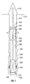
- Fig. 1 shows a schematic illustration of an embodiment of the present invention for drilling a borehole using a drilling liner. Shown is a rig 12 at the surface 10 of the earth in which a borehole 8 is drilled. A casing 14 has been set in the upper portion of the borehole. A drilling tubular 16 passes through the casing to a liner hanger/packer 18 at the bottom of the cased portion of the hole and carries a drilling liner - bottom hole assembly (DL-BHA) 22 at its lower end. The DL-BHA has, at its bottom end, a pilot bit 26 and a core bit 24. A liner 20 hangs from the liner hanger 18 at its top end is connected to the DL-BHA at its bottom end.
- the drilling tubular may be a drill pipe or coiled tubing.
- the liner hanger 18 connects the inner string, the outer line assembly and the drill pipe running string for the drilling mode. After completion of drilling, the liner hanger is set and the running tool disconnects from the liner. Desirable features for the liner hanger are:
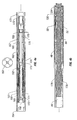
- FIGS 2A and 2B Details of the DL-BHA are shown in FIGS 2A and 2B. Shown at the top of FIG. 2A is a drilling tubular 16 to the surface and the liner hanger 18. The drilling tubular 16' below the liner hanger 18 may be of a smaller size than above the liner hanger 18. A thruster 34 is connected to the drilling tubular 16' and a drilling collar 16" connects the thruster 34 to the drilling liner inner assembly 30 while the liner 20 is connected to the drilling liner outer assembly 32.
- the drilling liner inner assembly 30 includes a drilling motor 40 , the pilot bit 24 , and a male sub 54 with drive splines 52 that transmit the torque from the motor 40 to the outer assembly: Landing splines 44 ensure a proper alignment of the inner assembly to the outer assembly.
- the outer assembly 32 includes the core bit 24 , a landing sub 46 , a suspension and bearing sub 48 and a female sub 50 that engages the drive splines 52 .
- the suspension and bearing sub 48 provides longitudinal length suspension and radial guidance and ensure that only the female sub 50 and the core bit 26 turn and the rest of the outer assembly remains without rotation.
- the downhole motor 40 provides the cutting torque and rotation.
- the thruster 34 provides a hydraulic weight on bit (WOB) and a dynamic length suspension.
- a standard drilling BHA is used to drill to the vicinity of a potential problem zone without the liner.
- the standard BHA is retrieved and the drilling liner is run in hole to continue further drilling through the problem zone. Once the problem zone has been traversed, the liner is set and the inner string is retrieved. Drilling may then continue below the problem zone and if a second problem zone is encountered, the process may be repeated.
- FIG. 3 shows a schematic illustration of a drilling liner system without the use of an inner string between the liner hanger and the DL-BHA motor. This eliminates the additional weight of the inner string to be carried by the rig. Furthermore it reduces the frictional forces between liner and hole when drilling in highly deviated hole sections. The maximum drilling distance in this kind of wells can be quite large. Shown is a rig 112 at the surface 110 of the earth in which a borehole 108 is drilled. A casing 114 has been set in the upper portion of the borehole. A drilling tubular 116 passes through the casing to a liner hanger 118 at the bottom of the cased portion of the hole.
- a liner 120 hangs from the liner hanger 118 at its top end is connected to the DL-BHA 122 at its bottom end.
- the DL-BHA has, at its bottom end, a pilot bit 126 and a core bit 124 . These are as discussed above with reference to FIG. 1.
- a landing sub is not necessary because the DL-BHA 122 is temporarily connected to the lower part of the liner 120 by means of a releasing tool 128.
- An inner string between the liner hanger 118 and the DL-BHA 122 is not required.
- the top of the releasing tool is provided with a fishable joint 130 that makes it possible to fish the DL-BHA 122 after the liner hanger/packer 118 is set.
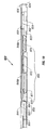
- FIG. 4 shows details of the DL-BHA with releasing tool 128.
- the BHA is connected to the Liner as shown in Figure 3 using the upper liner connection 164 .
- a cross over sub 175 is used to connect the outer part of the releasing tool to the outer portion of the lower drilling liner.
- the BHA has on it's bottom end a pilot bit 124, core bit 126, female sub 50, male sub 54, drive splines 52 and a downhole motor 40 as discussed under Fig. 1.
- a standard available downhole motor can be used.
- the motor features a screw on stabilizer 176 for centralization of the inner string inside the outer string.
- Fig. 4A shows details of the releasing tool.
- Releasing Tool instead of the shown Releasing Tool also standard components like e . g . a Baker Oil Tools sealing sub and running tool can be used .
- the preferred embodiment of the releasing tool combines the releasing mechanism and the sealing features in one single tool assembly to reduce the total length of the BHA. This makes it possible to pre-assemble the BHA offsite and send to the rig side as a single component.
- the releasing tool as shown under Fig. 4a features an outer string, which will stay in hole, and the inner string, which will be tripped out of hole after the liner is set.
- the inner string and the outer string are temporarily connected by means of the locking splines 162. Variations in length due to temperature changes, and errors in manufacturing tolerances, are compensated for by the axial stroke of the suspension ub 48.
- the outer string includes the top sub 161 with the upper liner connection 164, the locking sub 173 and the cross over sub 175.
- the cross over sub 175 is connected to the lower outer Drilling Liner BHA.
- the inner string constituting the retrievable parts comprises of the pulling sleeve 171 including a fishable joint 160, the stop sleeve 174, the optional seal carrier 168, locking splines 162, a first mandrel 169 and a second mandrel 170.
- the second mandrel 170 is connected on it's lower end to the downhole motor 40.
- Shear screws 166 keeping the pulling sleeve 171 and the first mandrel 169 temporarily connected. Shear screws 171 do not transmit operational drilling loads.
- the stop sleeve 174 prevents the locking splines 162 from retracting.
- the inner and outer string are sealed against each other by means of high pressure seals 163 and 176 .
- the fishing string When fishing the drilling liner inner string, the fishing string (not shown) is tripped in and connected to the pulling sleeve 171 .
- the make up torque when applied is transmitted from the pulling sleeve 171 via a toothed connection to the first mandrel 169.
- the shear screws 166 break, and the pulling sleeve 171 will move upwards until the stop sleeve 174 shoulders against the first mandrel 169.
- the seal carrier 168 build up a chamber to allow the locking splines 162 to retract.
- the locking splines 162 have inclined shoulders which generate a radial load on to the locking splines 162 when pulled.
- FIGS 3 and 4 has a number of advantages over the embodiment of FIGS. 1-2 .
- the trip time may be reduced in certain applications.
- the bottom hole assembly does not have any additional hydraulic components.
- the bottom hole assembly can be preassembled and the spacings checked out before delivery to the rig site.
- a standard mud motor can be used without any special bearings.
- the total hook load is less by the amount of weight of the inner string. There is less of a pressure drop because the mud is not passing through the small inner string. Kick control might be improved in some applications when tripping in the inner string.
- FIGS. 5A shows an embodiment of a steerable Drilling Liner system with a steerable drilling liner. Shown is a rig 212 at the surface 208 of the earth. A casing 214 has been set in the upper portion of the borehole. A drilling tubular 216 passes through the casing to a liner hanger 218 at the bottom of the cased portion of the hole and carries a drilling liner - bottom hole assembly (DL-BHA) 222 at its lower end. The DL-BHA has, at its bottom end, a pilot bit 226 and a core bit 224 . A liner 220 hangs from the liner hanger 218 at its top end and is connected to the DL-BHA at its bottom end. These are as discussed above with reference to FIG.
- DL-BHA drilling liner - bottom hole assembly
- the lower portion of the system has an MWD assembly 230 with a non-magnetic liner 232.
- the MWD assembly 230 offers directional control and can also provide information about the formation being traversed by it. This could include density, resistivity, gamma ray, NMR etc. measurements.
- the inner DL-BHA assembly 222 includes a flex shaft 234 between the motor and the male sub 254 and core bit 226.
- a radial bearing 256 supports the female sub 250 on the male sub 254.
- the liner 220 has a bent sub 236 that can be a fixed bend or an Adjustable Kick Off / bend Sub (AKO) making it possible to steer the liner under control of measurements from the MWD assembly 230.
- This device may also be used without an inner string between the DL-BHA and the liner hangers, similar to the arrangement discussed above with reference to FIG. 3 .
- FIG. 5B shows a steerable Drilling Liner system that differs from the system shown in FIG. 5A in that the motor 322, MWD device 330 and optional LWD (logging while drilling) are extending out of the core bit 324.
- the inner string is centralized inside the liner via stabilizers. There is no non-magnetic liner required. Instead of the flex shaft, male sub and pilot bit a standard stabilized motor 322 (motor stabilization is not shown) with AKO sub 336 and standard drill bit 326 is used on bottom of the inner string.
- AKO sub 336 standard drill bit 326 is used on bottom of the inner string.
- FIG. 6 Another arrangement of a steerable Drilling Liner system is shown in FIG. 6 .
- a rig 412 at the surface 410 of the earth.
- a casing 414 has been set in the upper portion of the borehole.
- a drilling tubular 416 passes through the casing to a liner hanger 418 at the bottom of the cased portion of the hole and carries a drilling liner bottom hole assembly (DL-BHA) 422 at its lower end.
- the DL-BHA has, at its bottom end, a pilot bit 426 and a core bit 424.
- a liner 420 hangs from the liner hanger 418 its top end is connected to the DL-BHA at its bottom end.
- the lower portion of the system has an MWD assembly 430 with a non-magnetic liner 432.
- the MWD assembly 430 offers directional control and can also provide information about the formation being traversed by it. This could include density, resistivity, gamma ray, NMR etc. measurements.
- the liner 420 can be steered downhole in inclination and azimuth by a steering system featuring retractable and expandable pads 438. In one embodiment of the invention, the pads 438 are on a non-rotatable sleeve. The liner is rotated within the sleeve whilst the sleeve is non-rotating.
- the sleeve itself features three or more pads which will be are loaded (expanded) or unloaded (retracted) to push the liner in the desired direction.
- the use of such a non-rotatable sleeve is would be known to those versed in the art.
- a commercial embodiment of this is the AUTOTRAK TM system of Baker Hughes and is not discussed further.
- An alternative is to use pads within the drilling liner. This device may also be used without an inner string between the DL-BHA and the liner hangers, similar to the arrangement discussed above with reference to FIG. 3 .
- FIG. 6 An alternate embodiment of the device shown in FIG. 6 uses an expandable stabilizer located at a suitable position 438 on the BHA (the position can vary depending on the application and needs). With such an arrangement, the expandable stabilizer serves as a pivot point enabling steering of the assembly. The use of such an expandable stabilizer would be known to those versed in the art and is not discussed further.
- FIG. 7 shows an embodiment of the invention using two additional packers. Shown is a rig 512 at the surface 510 of the earth in which a borehole 508 is drilled. A casing 514 has been set in the upper portion of the borehole. A drilling tubular 516 passes through the casing to a liner hanger 518 at the bottom of the cased portion of the hole and carries a drilling liner - bottom hole assembly (DL-BHA) 522 at its lower end. The DL-BHA has, at its bottom end, a pilot bit 526 and a core bit 524 A liner 520 hangs from the liner hanger 518 its top end is connected to the DL-BHA at its bottom end. These are as discussed above with reference to FIG. 1.
- DL-BHA drilling liner - bottom hole assembly
- Two additional packers are provided.
- One is a casing packer 552 just below the liner hanger 518.
- the other is an open hole packer 556 located close to the bit..
- the mud circulates in the direction indicated by 560, i.e., down the inner liner, out near the drill bit, back into the outer liner 520 through a port 554 , through the annulus between the inner liner and the outer liner 520 .
- the advantage of this invention is that there is no mud circulating in the annulus 550 between the outer liner 520 and the borehole 508 , so that the open hole is not affected by the dynamic pressure of the circulated mud system. This reduces the contamination of the formation by the circulating mud.
- This device may also be used with the steering arrangement ( FIG. 5A, 5B above) and with steerable pads ( FIG. 6 above).
- FIG. 8 shows an arrangement using an under-reamer on the outside of the outer casing. Shown is a rig 612 at the surface 610 of the earth. A casing 614 has been set in the upper portion of the borehole. A drilling tubular 616 passes through the casing to a liner hanger 618 at the bottom of the cased portion of the hole and carries a drilling liner - bottom hole assembly (DL-BHA) 622 at its lower end. The DL-BHA has, at its bottom end, a pilot bit 626 and a core bit 624. A liner 620 hangs from the liner hanger 618 at its top end is connected to the DL-BHA at its bottom end. These are as discussed above with reference to FIG. 1.
- DL-BHA drilling liner - bottom hole assembly
- the under-reamer 630 is placed in the lower outer part of the liner 620. With the use of the under-reamer to enlarge the hole drilled by the core bit, it is possible to overcome slip-stick or differential sticking problems or to run an expandable casing. This device may also be used without the inner string ( FIG. 3 above), with the steering arrangement ( FIG. 5A, 5B above) and with steerable pads ( FIG. 6 above).
- FIG. 9 illustrates another embodiment of the invention. Shown is a rig 712 at the surface 710 of the earth.
- a casing 714 has been set in the upper portion of the borehole.
- a drilling tubular 716 passes through the casing to a liner hanger 718 at the bottom of the cased portion of the hole and carries a drilling liner - bottom hole assembly (DL-BHA) 722 at its lower end.
- the DL-BHA has, at its bottom end, a pilot bit 726 and a core bit 724.
- a liner 720 hangs from the liner hanger 718 at its top end is connected to the DL-BHA at its bottom end.
- the core bit 724 is expandable, as indicated by the arrows 730. This makes it possible to expand the hole, making it possible to overcome stick-slip or differential sticking problems as well as to run an expandable casing.
- the pilot bit 726 may be made expandable, in which case, the core bit 724 is not necessary and the male sub with drive splines will not be required.
- the inner string may then be guided in a radial direction by means of stabilizer pads (not shown). This device may also be used without the inner liner ( FIG. 3 above), with the steering arrangement ( FIG. 5A, 5B above), with steerable pads ( FIG. 6 above) and with an under reamer ( FIG. 7 above).
- the invention discussed above with respect to FIGS. 1, 3, 5, 6 and 7 above may also be used with the use of a pilot bit including high pressure jet nozzles (not shown).
- the high fluid velocity exiting the nozzles washes the formation away to enlarge the hole size.
- the use of high pressure nozzles to wash out the formation would be known to those versed in the art and is not discussed further.
- With the use of such a special pilot bit it is possible to overcome stick-slip or differential sticking problems as well as to run an expandable casing.
- the well may be deviated in a desired direction by the use of jet nozzles. This requires a system that allows mud flow through the nozzles in only one direction.
- FIG. 10 provides a schematic illustration of a DL- BHA 822 where drilling may be continued with the drilling liner.
- the inner portion of the DL-BHA has an additional thruster, referred to as the bottom thruster 869 .
- the main parts of the bottom thruster are the cylinder 870 , the position indicator 871 , the piston 872 and the spline area 873 .
- the main portions of the drilling motor 859 are indicated as : the landing splines 860 , the bearing section 862 and the drive sub 864.
- the suspension sub has an inner and outer portion, labeled as 848b and 848a respectively.
- the male sub 854 is provided with drive splines 850 that engage the female sub.
- the pilot bit 824 is surrounded by the core bit 826 as in the other embodiments of the invention.
- the landing sub 844 couples the motor 859 to the suspension sub 848a, 848b .
- the core bit 826 is at the bottom of the hole at the same depth as the pilot bit 824 .
- the bottom thruster is completely closed and the inner portion of the suspension sub 848b is fully telescoped inside the outer part 848a . of the suspension sub. If it some point the outer liner (not shown in FIG. 9 ) gets stuck at some point at or above the motor 859 , the bottom thruster 869 is used to push the pilot bit 824 and the core bit 826 to continue drilling further into the formation until the thruster is fully extended.
- the female and male sub 854 are elongated by the stroke length of the bottom thruster 869 over what would normally be needed.
Landscapes
- Engineering & Computer Science (AREA)
- Life Sciences & Earth Sciences (AREA)
- Geology (AREA)
- Mining & Mineral Resources (AREA)
- Physics & Mathematics (AREA)
- Environmental & Geological Engineering (AREA)
- Fluid Mechanics (AREA)
- General Life Sciences & Earth Sciences (AREA)
- Geochemistry & Mineralogy (AREA)
- Mechanical Engineering (AREA)
- Earth Drilling (AREA)
Claims (31)
- Système de chemise de forage à utiliser lors du forage continu d'un trou de forage, comprenant un cuvelage (14; 114; 314; 414; 514; 614; 714) dans celui-ci, le cuvelage (14; 114; 314; 414; 514; 614; 714) contenant un tube de forage (16; 116; 216; 316; 416; 516; 616; 716) à l'intérieur, le système de chemise de forage comprenant en outre:caractérisé en ce que:un ensemble de trou de fond intérieur comprenant un moteur de forage (40; 322; 859) apte à être actionné par la boue charriée par ledit tube (16; 116; 216; 316; 416; 516; 616; 716), etun manchon mâle (54; 254; 854) mis en rotation par le moteur de forage (40; 322; 859), le manchon mâle (54; 254; 854) comportant sur lui des cannelures d'entraínement rétractables (52; 850) et étant couplé à un foret pilote (26; 126; 226; 326; 426; 526; 626; 726; 824) pour forer un trou pilote pendant le fonctionnement du moteur de forage (40; 322; 859);un ensemble de trou de fond extérieur comprenant un manchon femelle (50; 250) apte à engager les cannelures d'entraínement (52; 850) sur le manchon mâle (54; 254; 854) et à tourner avec le manchon mâle (54; 254; 854) lorsqu'il est engagé sur celui-ci; etune couronne de carottier (24; 124; 324; 424; 524; 624; 724; 826) qui entoure le foret pilote (26; 126; 226; 326; 426; 526; 626; 726; 824) et qui est couplée au manchon femelle (50; 250) pour forer un trou agrandi,un ensemble de suspension/bourrage de chemise (18; 118; 218; 318; 418; 518; 618; 718) est prévu au fond du cuvelage; etune chemise (20; 120; 220; 420; 520; 620; 720) est couplée par une première extrémité à l'ensemble de suspension/bourrage de chemise (18; 118; 218; 318; 418; 518; 618; 718) et par une deuxième extrémité à l'ensemble de trou de fond extérieur.
- Système de chemise de forage suivant la revendication 1, comprenant en outre un outil détachable (128) qui permet de coupler d'une façon détachable l'ensemble de trou de fond intérieur à la chemise (120).
- Système de chemise de forage suivant la revendication 2, comprenant en outre un joint de repêchage (130; 160) sur l'outil détachable (128) destiné à faciliter le retrait de l'ensemble de trou de fond intérieur hors du trou de forage.
- Système de chemise de forage suivant la revendication 1, 2 ou 3, comprenant en outre un dispositif MWD (230; 330; 430) dans l'ensemble de trou de fond intérieur destiné à procurer des mesures directionnelles et des dispositifs sur les ensembles de trou de fond intérieur et extérieur ayant pour but de faciliter le forage directionnel.
- Système de chemise de forage suivant la revendication 4, dans lequel les dispositifs sur les ensembles de trou de fond intérieur et extérieur destinés à faciliter le forage directionnel comprennent une pluralité de coussins rétractables (438) sur l'extérieur de l'ensemble de trou de fond extérieur, les coussins rétractables (438) étant aptes à engager la paroi du trou de forage et à guider le système de forage dans une direction souhaitée en inclinaison et en azimut.
- Système de chemise de forage suivant la revendication 4 ou 5, dans lequel une section de ladite chemise (220) est une section non magnétique (232).
- Système de chemise de forage suivant la revendication 4, 5 ou 6, dans lequel les dispositifs sur les ensembles de trou de fond intérieur et extérieur destinés à faciliter le forage directionnel comprennent un arbre flexible (234) entre le moteur et le manchon mâle (254), et un manchon coudé (236) sur l'ensemble de trou de fond extérieur au-dessus du manchon femelle (250), ledit manchon coudé (236) présentant un angle de démarrage réglable ou un angle fixe.
- Système de chemise de forage suivant l'une quelconque des revendications précédentes, comprenant en outre:un tube transportant un fluide de forage à partir du tube de forage jusqu'au moteur de forage (40; 322; 859) et jusqu'au foret pilote; etun bourrage de cuvelage (552) situé en dessous de l'ensemble de suspension/bourrage de chemise (518) et un bourrage de trou ouvert (556) situé à proximité de la couronne de carottier (526), le bourrage de cuvelage (552) et le bourrage de trou ouvert (556) empêchant un écoulement de fluide de forage dans un espace annulaire entre la chemise (520) et le trou de forage.
- Système de chemise de forage suivant l'une quelconque des revendications précédentes, dans lequel au moins un élément parmi (i) la couronne de carottier (24; 124; 324; 424; 524; 624; 724; 826), et (ii) le foret pilote (26; 126; 226; 326; 426; 526; 626; 726; 824) peut être expansé.
- Système de chemise de forage suivant l'une quelconque des revendications précédentes, dans lequel le foret pilote (26; 126; 226; 326; 426; 526; 626; 726; 824) comprend en outre des tuyères de projection à haute pression.
- Système de chemise de forage suivant l'une quelconque des revendications précédentes, comprenant en outre:un vérin (869) couplé au manchon mâle (854), le vérin (869) étant apte à étendre et à rétracter la position du manchon mâle (54; 254; 854) par rapport au moteur de forage (859); etun manchon de suspension télescopique couplé au moteur de forage (859) et au manchon femelle (50; 250), le manchon télescopique étant apte à déplacer le manchon femelle (50; 250) en conjonction avec le déplacement du vérin (869).
- Système de chemise de forage suivant l'une quelconque des revendications précédentes, comprenant en outre un manchon d'appui (844) comportant sur lui des cannelures (860) destinées à assurer l'alignement correct de l'ensemble de trou de fond intérieur avec l'ensemble de trou de fond extérieur.
- Système de chemise de forage suivant l'une quelconque des revendications précédentes, comprenant en outre un manchon de suspension et de support (848a, 848b) servant à procurer une suspension de longueur longitudinale et un guidage radial et à isoler la rotation du manchon femelle (50; 250) par rapport à la chemise.
- Système de chemise de forage suivant l'une quelconque des revendications précédentes, dans lequel le tube de forage (16; 116; 216; 316; 416; 516; 616; 716) comprend un tige de sondage ou un serpentin.
- Système de chemise de forage suivant l'une quelconque des revendications précédentes, comprenant en outre un alésoir (630) sur l'extérieur de l'ensemble de trou de fond extérieur, ledit alésoir (630) étant apte à agrandir le trou foré par la couronne de carottier.
- Procédé pour forer en continu un trou de forage comportant un cuvelage (14; 114; 314; 414; 514; 614; 714) dans une section de celui-ci, et un tube de forage (16; 116; 216; 316; 416; 516; 616; 716) disposé à l'intérieur du cuvelage, le procédé comprenant les étapes consistant à;
fournir un ensemble de trou de fond intérieur comprenant un moteur de forage (40) et un manchon mâle (54; 254; 854) comportant des cannelures d'entraínement rétractables (52; 850) et mis en rotation par le moteur de forage et couplé à un foret pilote (26; 126; 226; 326; 426; 526; 626; 726; 824);
fournir un ensemble de trou de fond extérieur, l'ensemble de trou de fond extérieur comprenant un manchon femelle (50; 250) comportant une couronne de carottier (24; 124; 324; 424; 524; 624; 724; 826) pour forer un trou agrandi, dans lequel ledit ensemble de trou de fond intérieur est disposé à proximité de l'ensemble de trou de fond extérieur,
le procédé étant caractérisé par:l'engagement du manchon femelle (50; 250) sur l'ensemble de trou de fond extérieur sur les cannelures d'entraínement (52; 850) présentes sur le manchon mâle (54; 254; 854) permettant de ce fait à la couronne de carottier (24; 124; 324; 424; 524; 624; 724; 826) de forer un trou agrandi lors du fonctionnement du moteur de forage (40; 322; 859);la fourniture d'un ensemble de suspension/bourrage de chemise (18; 118; 218; 318; 418; 518; 618; 718) au fond du cuvelage;le couplage d'une chemise (20; 120; 220; 420; 520; 620; 720) par une première extrémité à l'ensemble de suspension/bourrage de chemise (18; 118; 218; 318; 418; 518; 618; 718) et par une deuxième extrémité à l'ensemble de trou de fond extérieur;le couplage d'une deuxième extrémité de la chemise (120) à l'ensemble de trou de fond extérieur; etle forage d'un trou pilote en actionnant le moteur de forage (40; 322; 859) en faisant passer la boue charriée par ledit tube. - Procédé suivant la revendication 16, comprenant en outre le couplage détachable d'un outil détachable (128) de l'ensemble de trou de fond intérieur à la chemise (120).
- Procédé suivant la revendication 17, comprenant en outre la fourniture d'un joint de repêchage (130; 160) sur l'outil de fixation (128) destiné à faciliter le retrait de l'ensemble de trou de fond intérieur hors du trou de forage.
- Procédé suivant la revendication 16, 17 ou 18, comprenant en outre:l'utilisation d'un dispositif MWD (230; 330; 430) destiné à procurer des mesures directionnelles; etl'utilisation de dispositifs sur les ensembles de trou de fond intérieur et extérieur dans le but de faciliter le forage directionnel.
- Procédé suivant la revendication 19, comprenant en outre:l'utilisation d'une pluralité de coussins rétractables (438) sur l'extérieur de l'ensemble de trou de fond extérieur afin d'engager la paroi du trou de forage; etle guidage des ensembles de trou de fond intérieur et extérieur dans une direction souhaitée en inclinaison et en azimut avec les coussins rétractables.
- Procédé suivant la revendication 19 ou 20, comprenant en outre la fourniture d'une section non magnétique (232) sur ladite chemise (220).
- Procédé suivant la revendication 19, 20 ou 21, comprenant en outre le guidage des ensembles de trou de fond intérieur et extérieur durant le forage directionnel en utilisant un arbre flexible (234) entre le moteur et le manchon mâle (254), et un manchon coudé (236) sur l'ensemble de trou de fond extérieur au-dessus du manchon femelle (250), ledit manchon coudé (236) présentant un angle de démarrage réglable ou un angle fixe.
- Procédé suivant l'une quelconque des revendications 16 à 22, comprenant en outre l'utilisation d'un bourrage de cuvelage (552) situé en dessous de l'ensemble de suspension/bourrage de chemise (518) et d'un bourrage de trou ouvert (556) situé à proximité de la couronne de carottier (526) et destiné à empêcher l'écoulement des fluides de forage dans un espace annulaire entre la chemise (520) et le trou de forage.
- Procédé de forage suivant l'une quelconque des revendications 16 à 23, dans lequel au moins un élément parmi (i) la couronne de carottier (24; 124; 324; 424; 524; 624; 724; 826), et (ii) le foret pilote (26; 126; 226; 326; 426; 526; 626; 726; 824) peut être expansé.
- Procédé suivant l'une quelconque des revendications 16 à 24, dans lequel le foret pilote (26; 126; 226; 326; 426; 526; 626; 726; 824) comprend en outre des tuyères de projection à haute pression.
- Procédé suivant l'une quelconque des revendications 16 à 25, comprenant en outre:le couplage d'un vérin (869) au manchon mâle (854), le vérin (869) étant apte à étendre et à rétracter la position du manchon mâle (854) par rapport au moteur de forage (859);le couplage d'un manchon de suspension télescopique au moteur de forage (859) et au manchon femelle; etle déplacement du manchon femelle en conjonction avec le déplacement du vérin (869) en utilisant le manchon télescopique.
- Procédé suivant l'une quelconque des revendications 16 à 26, comprenant en outre l'alignement de l'ensemble de trou de fond intérieur et de l'ensemble de trou de fond extérieur en utilisant un manchon d'appui (844) comportant sur lui des cannelures (860).
- Procédé suivant l'une quelconque des revendications 18 à 27, comprenant en outre:la fourniture d'une suspension de longueur longitudinale et d'un guidage radial en utilisant un manchon de suspension et de support (848a, 848b); etl'isolation de la rotation du manchon femelle par rapport à la chemise.
- Procédé suivant l'une quelconque des revendications 16 à 28, dans lequel le tube de forage (16; 116; 216; 316; 416; 516; 616; 716) comprend une tige de sondage ou un serpentin.
- Procédé suivant l'une quelconque des revendications 16 à 29, comprenant en outre un alésoir (630) sur l'extérieur de l'ensemble de trou de fond extérieur, ledit alésoir (630) étant apte à agrandir le trou foré par la couronne de carottier (624).
- Procédé suivant l'une quelconque des revendications 16 à 30, comprenant en outre l'utilisation d'un vérin (869) sur l'ensemble de trou de fond intérieur afin de déplacer le manchon mâle (854) par rapport au moteur de forage (859), et l'utilisation d'un manchon de suspension télescopique sur l'ensemble de trou de fond extérieur afin de maintenir un engagement entre le manchon femelle et les cannelures d'entraínement (850) présentes sur le manchon mâle (854).
Applications Claiming Priority (2)
| Application Number | Priority Date | Filing Date | Title |
|---|---|---|---|
| US09/205,969 US6196336B1 (en) | 1995-10-09 | 1998-12-04 | Method and apparatus for drilling boreholes in earth formations (drilling liner systems) |
| US205969 | 1998-12-04 |
Publications (3)
| Publication Number | Publication Date |
|---|---|
| EP1006260A2 EP1006260A2 (fr) | 2000-06-07 |
| EP1006260A3 EP1006260A3 (fr) | 2002-02-06 |
| EP1006260B1 true EP1006260B1 (fr) | 2004-04-21 |
Family
ID=22764433
Family Applications (1)
| Application Number | Title | Priority Date | Filing Date |
|---|---|---|---|
| EP99309769A Expired - Lifetime EP1006260B1 (fr) | 1998-12-04 | 1999-12-06 | Systèmes de chemises de forage |
Country Status (5)
| Country | Link |
|---|---|
| US (1) | US6196336B1 (fr) |
| EP (1) | EP1006260B1 (fr) |
| CA (1) | CA2291535C (fr) |
| DE (1) | DE69916556T2 (fr) |
| NO (1) | NO316759B1 (fr) |
Cited By (57)
| Publication number | Priority date | Publication date | Assignee | Title |
|---|---|---|---|---|
| US6857487B2 (en) | 2002-12-30 | 2005-02-22 | Weatherford/Lamb, Inc. | Drilling with concentric strings of casing |
| US6896075B2 (en) | 2002-10-11 | 2005-05-24 | Weatherford/Lamb, Inc. | Apparatus and methods for drilling with casing |
| US6899186B2 (en) | 2002-12-13 | 2005-05-31 | Weatherford/Lamb, Inc. | Apparatus and method of drilling with casing |
| US6953096B2 (en) | 2002-12-31 | 2005-10-11 | Weatherford/Lamb, Inc. | Expandable bit with secondary release device |
| US6994176B2 (en) | 2002-07-29 | 2006-02-07 | Weatherford/Lamb, Inc. | Adjustable rotating guides for spider or elevator |
| US7004264B2 (en) | 2002-03-16 | 2006-02-28 | Weatherford/Lamb, Inc. | Bore lining and drilling |
| US7013997B2 (en) | 1994-10-14 | 2006-03-21 | Weatherford/Lamb, Inc. | Methods and apparatus for cementing drill strings in place for one pass drilling and completion of oil and gas wells |
| US7036610B1 (en) | 1994-10-14 | 2006-05-02 | Weatherford / Lamb, Inc. | Apparatus and method for completing oil and gas wells |
| US7040420B2 (en) | 1994-10-14 | 2006-05-09 | Weatherford/Lamb, Inc. | Methods and apparatus for cementing drill strings in place for one pass drilling and completion of oil and gas wells |
| US7048050B2 (en) | 1994-10-14 | 2006-05-23 | Weatherford/Lamb, Inc. | Method and apparatus for cementing drill strings in place for one pass drilling and completion of oil and gas wells |
| US7073598B2 (en) | 2001-05-17 | 2006-07-11 | Weatherford/Lamb, Inc. | Apparatus and methods for tubular makeup interlock |
| US7090021B2 (en) | 1998-08-24 | 2006-08-15 | Bernd-Georg Pietras | Apparatus for connecting tublars using a top drive |
| US7093675B2 (en) | 2000-08-01 | 2006-08-22 | Weatherford/Lamb, Inc. | Drilling method |
| US7096982B2 (en) | 2003-02-27 | 2006-08-29 | Weatherford/Lamb, Inc. | Drill shoe |
| US7100713B2 (en) | 2000-04-28 | 2006-09-05 | Weatherford/Lamb, Inc. | Expandable apparatus for drift and reaming borehole |
| US7100710B2 (en) | 1994-10-14 | 2006-09-05 | Weatherford/Lamb, Inc. | Methods and apparatus for cementing drill strings in place for one pass drilling and completion of oil and gas wells |
| US7108084B2 (en) | 1994-10-14 | 2006-09-19 | Weatherford/Lamb, Inc. | Methods and apparatus for cementing drill strings in place for one pass drilling and completion of oil and gas wells |
| US7117957B2 (en) | 1998-12-22 | 2006-10-10 | Weatherford/Lamb, Inc. | Methods for drilling and lining a wellbore |
| US7128161B2 (en) | 1998-12-24 | 2006-10-31 | Weatherford/Lamb, Inc. | Apparatus and methods for facilitating the connection of tubulars using a top drive |
| US7128154B2 (en) | 2003-01-30 | 2006-10-31 | Weatherford/Lamb, Inc. | Single-direction cementing plug |
| US7137454B2 (en) | 1998-07-22 | 2006-11-21 | Weatherford/Lamb, Inc. | Apparatus for facilitating the connection of tubulars using a top drive |
| US7140445B2 (en) | 1997-09-02 | 2006-11-28 | Weatherford/Lamb, Inc. | Method and apparatus for drilling with casing |
| US7147068B2 (en) | 1994-10-14 | 2006-12-12 | Weatherford / Lamb, Inc. | Methods and apparatus for cementing drill strings in place for one pass drilling and completion of oil and gas wells |
| US7188687B2 (en) | 1998-12-22 | 2007-03-13 | Weatherford/Lamb, Inc. | Downhole filter |
| US7191840B2 (en) | 2003-03-05 | 2007-03-20 | Weatherford/Lamb, Inc. | Casing running and drilling system |
| US7213656B2 (en) | 1998-12-24 | 2007-05-08 | Weatherford/Lamb, Inc. | Apparatus and method for facilitating the connection of tubulars using a top drive |
| US7216727B2 (en) | 1999-12-22 | 2007-05-15 | Weatherford/Lamb, Inc. | Drilling bit for drilling while running casing |
| US7219744B2 (en) | 1998-08-24 | 2007-05-22 | Weatherford/Lamb, Inc. | Method and apparatus for connecting tubulars using a top drive |
| US7228901B2 (en) | 1994-10-14 | 2007-06-12 | Weatherford/Lamb, Inc. | Method and apparatus for cementing drill strings in place for one pass drilling and completion of oil and gas wells |
| US7264067B2 (en) | 2003-10-03 | 2007-09-04 | Weatherford/Lamb, Inc. | Method of drilling and completing multiple wellbores inside a single caisson |
| US7267175B2 (en) | 2000-05-05 | 2007-09-11 | Weatherford/Lamb, Inc. | Apparatus and methods for forming a lateral wellbore |
| US7284617B2 (en) | 2004-05-20 | 2007-10-23 | Weatherford/Lamb, Inc. | Casing running head |
| US7303022B2 (en) | 2002-10-11 | 2007-12-04 | Weatherford/Lamb, Inc. | Wired casing |
| US7311148B2 (en) | 1999-02-25 | 2007-12-25 | Weatherford/Lamb, Inc. | Methods and apparatus for wellbore construction and completion |
| US7325610B2 (en) | 2000-04-17 | 2008-02-05 | Weatherford/Lamb, Inc. | Methods and apparatus for handling and drilling with tubulars or casing |
| US7334650B2 (en) | 2000-04-13 | 2008-02-26 | Weatherford/Lamb, Inc. | Apparatus and methods for drilling a wellbore using casing |
| US7360594B2 (en) | 2003-03-05 | 2008-04-22 | Weatherford/Lamb, Inc. | Drilling with casing latch |
| US7370707B2 (en) | 2003-04-04 | 2008-05-13 | Weatherford/Lamb, Inc. | Method and apparatus for handling wellbore tubulars |
| US7395882B2 (en) | 2004-02-19 | 2008-07-08 | Baker Hughes Incorporated | Casing and liner drilling bits |
| US7413020B2 (en) | 2003-03-05 | 2008-08-19 | Weatherford/Lamb, Inc. | Full bore lined wellbores |
| US7503397B2 (en) | 2004-07-30 | 2009-03-17 | Weatherford/Lamb, Inc. | Apparatus and methods of setting and retrieving casing with drilling latch and bottom hole assembly |
| US7509722B2 (en) | 1997-09-02 | 2009-03-31 | Weatherford/Lamb, Inc. | Positioning and spinning device |
| US7617866B2 (en) | 1998-08-24 | 2009-11-17 | Weatherford/Lamb, Inc. | Methods and apparatus for connecting tubulars using a top drive |
| US7621351B2 (en) | 2006-05-15 | 2009-11-24 | Baker Hughes Incorporated | Reaming tool suitable for running on casing or liner |
| US7624818B2 (en) | 2004-02-19 | 2009-12-01 | Baker Hughes Incorporated | Earth boring drill bits with casing component drill out capability and methods of use |
| US7650944B1 (en) | 2003-07-11 | 2010-01-26 | Weatherford/Lamb, Inc. | Vessel for well intervention |
| US7712523B2 (en) | 2000-04-17 | 2010-05-11 | Weatherford/Lamb, Inc. | Top drive casing system |
| US7730965B2 (en) | 2002-12-13 | 2010-06-08 | Weatherford/Lamb, Inc. | Retractable joint and cementing shoe for use in completing a wellbore |
| US7857052B2 (en) | 2006-05-12 | 2010-12-28 | Weatherford/Lamb, Inc. | Stage cementing methods used in casing while drilling |
| US7938201B2 (en) | 2002-12-13 | 2011-05-10 | Weatherford/Lamb, Inc. | Deep water drilling with casing |
| US7954570B2 (en) | 2004-02-19 | 2011-06-07 | Baker Hughes Incorporated | Cutting elements configured for casing component drillout and earth boring drill bits including same |
| US7954571B2 (en) | 2007-10-02 | 2011-06-07 | Baker Hughes Incorporated | Cutting structures for casing component drillout and earth-boring drill bits including same |
| USRE42877E1 (en) | 2003-02-07 | 2011-11-01 | Weatherford/Lamb, Inc. | Methods and apparatus for wellbore construction and completion |
| US8245797B2 (en) | 2007-10-02 | 2012-08-21 | Baker Hughes Incorporated | Cutting structures for casing component drillout and earth-boring drill bits including same |
| US8276689B2 (en) | 2006-05-22 | 2012-10-02 | Weatherford/Lamb, Inc. | Methods and apparatus for drilling with casing |
| US10260295B2 (en) | 2017-05-26 | 2019-04-16 | Saudi Arabian Oil Company | Mitigating drilling circulation loss |
| US10545037B2 (en) | 2016-08-01 | 2020-01-28 | Saudi Arabian Oil Company | Flow line insert with indentations |
Families Citing this family (113)
| Publication number | Priority date | Publication date | Assignee | Title |
|---|---|---|---|---|
| US6857486B2 (en) | 2001-08-19 | 2005-02-22 | Smart Drilling And Completion, Inc. | High power umbilicals for subterranean electric drilling machines and remotely operated vehicles |
| US8011450B2 (en) * | 1998-07-15 | 2011-09-06 | Baker Hughes Incorporated | Active bottomhole pressure control with liner drilling and completion systems |
| US6712154B2 (en) | 1998-11-16 | 2004-03-30 | Enventure Global Technology | Isolation of subterranean zones |
| US7357188B1 (en) | 1998-12-07 | 2008-04-15 | Shell Oil Company | Mono-diameter wellbore casing |
| US6823937B1 (en) | 1998-12-07 | 2004-11-30 | Shell Oil Company | Wellhead |
| US6575240B1 (en) | 1998-12-07 | 2003-06-10 | Shell Oil Company | System and method for driving pipe |
| US6745845B2 (en) | 1998-11-16 | 2004-06-08 | Shell Oil Company | Isolation of subterranean zones |
| US6557640B1 (en) * | 1998-12-07 | 2003-05-06 | Shell Oil Company | Lubrication and self-cleaning system for expansion mandrel |
| US7121352B2 (en) | 1998-11-16 | 2006-10-17 | Enventure Global Technology | Isolation of subterranean zones |
| US7231985B2 (en) | 1998-11-16 | 2007-06-19 | Shell Oil Company | Radial expansion of tubular members |
| US6634431B2 (en) | 1998-11-16 | 2003-10-21 | Robert Lance Cook | Isolation of subterranean zones |
| US7603758B2 (en) | 1998-12-07 | 2009-10-20 | Shell Oil Company | Method of coupling a tubular member |
| GB2384502B (en) | 1998-11-16 | 2004-10-13 | Shell Oil Co | Coupling an expandable tubular member to a preexisting structure |
| US7185710B2 (en) | 1998-12-07 | 2007-03-06 | Enventure Global Technology | Mono-diameter wellbore casing |
| GB2356651B (en) | 1998-12-07 | 2004-02-25 | Shell Int Research | Lubrication and self-cleaning system for expansion mandrel |
| US7552776B2 (en) | 1998-12-07 | 2009-06-30 | Enventure Global Technology, Llc | Anchor hangers |
| US6758278B2 (en) | 1998-12-07 | 2004-07-06 | Shell Oil Company | Forming a wellbore casing while simultaneously drilling a wellbore |
| US7195064B2 (en) | 1998-12-07 | 2007-03-27 | Enventure Global Technology | Mono-diameter wellbore casing |
| GB2344606B (en) * | 1998-12-07 | 2003-08-13 | Shell Int Research | Forming a wellbore casing by expansion of a tubular member |
| US7363984B2 (en) | 1998-12-07 | 2008-04-29 | Enventure Global Technology, Llc | System for radially expanding a tubular member |
| CA2271401C (fr) | 1999-02-23 | 2008-07-29 | Tesco Corporation | Forage avec tubage |
| US6854533B2 (en) * | 2002-12-20 | 2005-02-15 | Weatherford/Lamb, Inc. | Apparatus and method for drilling with casing |
| AU770359B2 (en) | 1999-02-26 | 2004-02-19 | Shell Internationale Research Maatschappij B.V. | Liner hanger |
| US7055608B2 (en) | 1999-03-11 | 2006-06-06 | Shell Oil Company | Forming a wellbore casing while simultaneously drilling a wellbore |
| CA2306656C (fr) * | 1999-04-26 | 2006-06-06 | Shell Internationale Research Maatschappij B.V. | Connexion extensible |
| US7350563B2 (en) | 1999-07-09 | 2008-04-01 | Enventure Global Technology, L.L.C. | System for lining a wellbore casing |
| US9586699B1 (en) | 1999-08-16 | 2017-03-07 | Smart Drilling And Completion, Inc. | Methods and apparatus for monitoring and fixing holes in composite aircraft |
| AU783245B2 (en) | 1999-11-01 | 2005-10-06 | Shell Internationale Research Maatschappij B.V. | Wellbore casing repair |
| US7234531B2 (en) | 1999-12-03 | 2007-06-26 | Enventure Global Technology, Llc | Mono-diameter wellbore casing |
| US6578630B2 (en) | 1999-12-22 | 2003-06-17 | Weatherford/Lamb, Inc. | Apparatus and methods for expanding tubulars in a wellbore |
| US20060124306A1 (en) * | 2000-01-19 | 2006-06-15 | Vail William B Iii | Installation of one-way valve after removal of retrievable drill bit to complete oil and gas wells |
| US7100684B2 (en) | 2000-07-28 | 2006-09-05 | Enventure Global Technology | Liner hanger with standoffs |
| AU9269501A (en) | 2000-09-18 | 2002-03-26 | Shell Oil Co | Liner hanger with sliding sleeve valve |
| GB2389597B (en) | 2000-10-02 | 2005-05-18 | Shell Oil Co | Plastically deforming and radially expanding a tubular member |
| WO2002053867A2 (fr) | 2001-01-03 | 2002-07-11 | Enventure Global Technology | Cuvelage de diamètre nanométrique pour puits foré |
| US7100685B2 (en) | 2000-10-02 | 2006-09-05 | Enventure Global Technology | Mono-diameter wellbore casing |
| US7410000B2 (en) | 2001-01-17 | 2008-08-12 | Enventure Global Technology, Llc. | Mono-diameter wellbore casing |
| US7004263B2 (en) * | 2001-05-09 | 2006-02-28 | Schlumberger Technology Corporation | Directional casing drilling |
| GB2395506B (en) | 2001-07-06 | 2006-01-18 | Eventure Global Technology | Liner hanger |
| CA2453063C (fr) | 2001-07-06 | 2011-03-22 | Enventure Global Technology | Suspension de colonne perdue |
| US7258168B2 (en) | 2001-07-27 | 2007-08-21 | Enventure Global Technology L.L.C. | Liner hanger with slip joint sealing members and method of use |
| WO2003012242A1 (fr) * | 2001-07-30 | 2003-02-13 | Smith International, Inc. | Instrument de verrouillage de moteur de perforation vers le bas |
| US9625361B1 (en) | 2001-08-19 | 2017-04-18 | Smart Drilling And Completion, Inc. | Methods and apparatus to prevent failures of fiber-reinforced composite materials under compressive stresses caused by fluids and gases invading microfractures in the materials |
| US8515677B1 (en) | 2002-08-15 | 2013-08-20 | Smart Drilling And Completion, Inc. | Methods and apparatus to prevent failures of fiber-reinforced composite materials under compressive stresses caused by fluids and gases invading microfractures in the materials |
| US9284780B2 (en) * | 2001-08-19 | 2016-03-15 | Smart Drilling And Completion, Inc. | Drilling apparatus |
| US7793721B2 (en) | 2003-03-11 | 2010-09-14 | Eventure Global Technology, Llc | Apparatus for radially expanding and plastically deforming a tubular member |
| WO2003023178A2 (fr) | 2001-09-07 | 2003-03-20 | Enventure Global Technology | Ensemble cone d'expansion reglable |
| GB2422859B (en) | 2001-11-12 | 2006-12-13 | Enventure Global Technology | Collapsible expansion cone |
| US7066284B2 (en) * | 2001-11-14 | 2006-06-27 | Halliburton Energy Services, Inc. | Method and apparatus for a monodiameter wellbore, monodiameter casing, monobore, and/or monowell |
| AU2002367348A1 (en) | 2001-12-27 | 2003-07-24 | Enventure Global Technology | Seal receptacle using expandable liner hanger |
| WO2003089161A2 (fr) | 2002-04-15 | 2003-10-30 | Enventure Global Technlogy | Manchon protecteur destine aux connexions filetees d'un dispositif de suspension pour colonne de tubage perdue expansible |
| US7424918B2 (en) | 2002-08-23 | 2008-09-16 | Enventure Global Technology, L.L.C. | Interposed joint sealing layer method of forming a wellbore casing |
| WO2004018824A2 (fr) | 2002-08-23 | 2004-03-04 | Enventure Global Technology | Impulsion magnetique appliquee sur un manchon et procede de formation d'un tubage de puits de forage |
| CN100338331C (zh) | 2002-01-17 | 2007-09-19 | 普雷斯索有限公司 | 用同心钻柱钻井眼的方法和装置 |
| CA2473372C (fr) | 2002-01-22 | 2012-11-20 | Presssol Ltd. | Systeme de forage a double train equipe d'un tube spirale |
| ATE417993T1 (de) | 2002-02-15 | 2009-01-15 | Enventure Global Technology | Bohrlochfutterrohr mit einem einzigen durchmesser |
| NO316183B1 (no) * | 2002-03-08 | 2003-12-22 | Sigbjoern Sangesland | Fremgangsmåte og anordning ved fôringsrör |
| AU2003215290A1 (en) * | 2002-03-13 | 2003-09-29 | Eventure Global Technology | Collapsible expansion cone |
| EP1985797B1 (fr) | 2002-04-12 | 2011-10-26 | Enventure Global Technology | Manchon protecteur pour connexions filetées pour support de conduite extensible |
| AU2003225001A1 (en) | 2002-05-29 | 2003-12-19 | Eventure Global Technology | System for radially expanding a tubular member |
| GB2418944B (en) | 2002-06-10 | 2006-08-30 | Enventure Global Technology | Mono Diameter Wellbore Casing |
| AU2003260217A1 (en) | 2002-07-19 | 2004-02-09 | Presssol Ltd. | Reverse circulation clean out system for low pressure gas wells |
| AU2003260210A1 (en) * | 2002-08-21 | 2004-03-11 | Presssol Ltd. | Reverse circulation directional and horizontal drilling using concentric coil tubing |
| WO2004027392A1 (fr) | 2002-09-20 | 2004-04-01 | Enventure Global Technology | Evaluation de formabilite de conduite pour des elements tubulaires extensibles |
| CA2499007C (fr) | 2002-09-20 | 2012-08-07 | Enventure Global Technology | Bouchon inferieur pour la formation d'un tubage de puits de forage de diametre unique |
| AU2003263859A1 (en) | 2002-09-20 | 2004-04-08 | Enventure Global Technology | Protective sleeve for expandable tubulars |
| CA2499071C (fr) | 2002-09-20 | 2014-06-03 | Enventure Global Technology | Mandrin d'extension autolubrifiant pour element tubulaire extensible |
| US6799645B2 (en) * | 2002-12-10 | 2004-10-05 | Shell Oil Company | Method and apparatus for drilling and completing a well with an expandable sand control system |
| US7886831B2 (en) | 2003-01-22 | 2011-02-15 | Enventure Global Technology, L.L.C. | Apparatus for radially expanding and plastically deforming a tubular member |
| WO2004076798A2 (fr) | 2003-02-26 | 2004-09-10 | Enventure Global Technology | Appareil d'expansion radiale et de deformation plastique d'un element tubulaire |
| US7503393B2 (en) | 2003-01-27 | 2009-03-17 | Enventure Global Technology, Inc. | Lubrication system for radially expanding tubular members |
| EP2278111A3 (fr) * | 2003-01-31 | 2017-12-06 | Weatherford Technology Holdings, LLC | Appareil et procédés permettant de forer un puits utilisant un cuvelage |
| ATE442510T1 (de) * | 2003-03-13 | 2009-09-15 | Tesco Corp | Verfahren und vorrichtung zum bohren eines bohrlochs mit einem bohrloch-liner |
| GB2415988B (en) | 2003-04-17 | 2007-10-17 | Enventure Global Technology | Apparatus for radially expanding and plastically deforming a tubular member |
| BRPI0410463B1 (pt) * | 2003-05-21 | 2015-08-25 | Shell Int Research | Broca de perfuração para perfurar um furo de sondagem em um objeto |
| US20050166387A1 (en) | 2003-06-13 | 2005-08-04 | Cook Robert L. | Method and apparatus for forming a mono-diameter wellbore casing |
| US7712522B2 (en) | 2003-09-05 | 2010-05-11 | Enventure Global Technology, Llc | Expansion cone and system |
| US7757784B2 (en) | 2003-11-17 | 2010-07-20 | Baker Hughes Incorporated | Drilling methods utilizing independently deployable multiple tubular strings |
| US7086485B2 (en) * | 2003-12-12 | 2006-08-08 | Schlumberger Technology Corporation | Directional casing drilling |
| US20050126826A1 (en) * | 2003-12-12 | 2005-06-16 | Moriarty Keith A. | Directional casing and liner drilling with mud motor |
| US20050133268A1 (en) * | 2003-12-17 | 2005-06-23 | Moriarty Keith A. | Method and apparatus for casing and directional drilling using bi-centered bit |
| US7182153B2 (en) * | 2004-01-09 | 2007-02-27 | Schlumberger Technology Corporation | Methods of casing drilling |
| US7343983B2 (en) * | 2004-02-11 | 2008-03-18 | Presssol Ltd. | Method and apparatus for isolating and testing zones during reverse circulation drilling |
| CA2496956C (fr) * | 2004-02-12 | 2009-03-10 | Presssol Ltd. | Bloc obturateur de forage a circulation inverse |
| NO325291B1 (no) * | 2004-03-08 | 2008-03-17 | Reelwell As | Fremgangsmate og anordning for etablering av en undergrunns bronn. |
| US20050252661A1 (en) * | 2004-05-13 | 2005-11-17 | Presssol Ltd. | Casing degasser tool |
| CA2572240C (fr) * | 2004-06-24 | 2010-09-28 | Baker Hughes Incorporated | Systemes de forage et procedes d'utilisation de multiples sequences de tubes deployables separement |
| GB2432866A (en) | 2004-08-13 | 2007-06-06 | Enventure Global Technology | Expandable tubular |
| US8827006B2 (en) * | 2005-05-12 | 2014-09-09 | Schlumberger Technology Corporation | Apparatus and method for measuring while drilling |
| US7766088B2 (en) * | 2005-07-07 | 2010-08-03 | Baker Hughes Incorporated | System and method for actuating wellbore tools |
| NO323198B1 (no) * | 2005-07-11 | 2007-01-15 | Statoil Asa | Innretning ved fôringsror eller forlengelsesror, fremgangsmate for innsetting av fôringsror eller forlengelsesror, og innretning ved boreror. |
| WO2007011906A1 (fr) * | 2005-07-19 | 2007-01-25 | Baker Hughes Incorporated | Ensemble de suspension verrouillable pour forage et completion par colonnes perdues |
| GB0515394D0 (en) * | 2005-07-27 | 2005-08-31 | Schlumberger Holdings | Steerable drilling system |
| US7416036B2 (en) * | 2005-08-12 | 2008-08-26 | Baker Hughes Incorporated | Latchable reaming bit |
| GB2449594B (en) * | 2006-03-02 | 2010-11-17 | Baker Hughes Inc | Automated steerable hole enlargement drilling device and methods |
| US8875810B2 (en) * | 2006-03-02 | 2014-11-04 | Baker Hughes Incorporated | Hole enlargement drilling device and methods for using same |
| US8056649B2 (en) * | 2007-08-30 | 2011-11-15 | Baker Hughes Incorporated | Apparatus and methods for drilling wellbores that utilize a detachable reamer |
| WO2009029800A1 (fr) * | 2007-08-30 | 2009-03-05 | Baker Hughes Incorporated | Appareil et procédé de forage de puits utilisant un aléseur libérable |
| BRPI0821578A2 (pt) * | 2007-12-10 | 2015-06-16 | Shell Int Research | Sistema para perfurar um furo de poço em uma formação terrestre |
| US9062497B2 (en) * | 2008-10-29 | 2015-06-23 | Baker Hughes Incorporated | Phase estimation from rotating sensors to get a toolface |
| EP3272994A1 (fr) * | 2008-11-17 | 2018-01-24 | Weatherford Technology Holdings, LLC | Forage sous-marin avec boîtier |
| WO2011046859A2 (fr) * | 2009-10-12 | 2011-04-21 | Shell Oil Company | Système de tubage rotatif dirigeable pour forage |
| US9045946B2 (en) * | 2010-09-23 | 2015-06-02 | Baker Hughes Incorporated | Apparatus and method for drilling wellbores |
| US8973676B2 (en) | 2011-07-28 | 2015-03-10 | Baker Hughes Incorporated | Active equivalent circulating density control with real-time data connection |
| WO2013126822A2 (fr) | 2012-02-22 | 2013-08-29 | Weatherford/Lamb, Inc. | Système de forage à tubage sous-marin |
| US9022113B2 (en) | 2012-05-09 | 2015-05-05 | Baker Hughes Incorporated | One trip casing or liner directional drilling with expansion and cementing |
| US10329863B2 (en) * | 2013-08-06 | 2019-06-25 | A&O Technologies LLC | Automatic driller |
| CN103993846B (zh) * | 2014-04-22 | 2016-08-24 | 美钻能源科技(上海)有限公司 | 一种泥线悬挂器 |
| CN107429541B (zh) | 2015-04-16 | 2019-11-29 | 哈利伯顿能源服务公司 | 具有对准壳体孔的定向钻井设备 |
| CA3040172C (fr) | 2016-12-01 | 2022-05-10 | Halliburton Energy Services, Inc. | Systeme de forage a colonne perdue de puits de forage en une seule manoeuvre |
| EP3631139A1 (fr) * | 2017-05-25 | 2020-04-08 | National Oilwell DHT, L.P. | Ensembles à incurvation réglable de fond de trou |
| CN107060731A (zh) * | 2017-07-04 | 2017-08-18 | 中国石油集团钻井工程技术研究院 | 一种基于井涌余量的深水钻井套管下深修正方法 |
| CN112696154B (zh) * | 2019-10-21 | 2024-11-26 | 中国石油化工集团有限公司 | 用于定向尾管钻井的尾管钻进组件 |
Family Cites Families (12)
| Publication number | Priority date | Publication date | Assignee | Title |
|---|---|---|---|---|
| GB1249440A (en) * | 1970-06-17 | 1971-10-13 | Shell Int Research | Method and apparatus for use in drilling offshore wells |
| FR2209038B1 (fr) * | 1972-12-06 | 1977-07-22 | Petroles Cie Francaise | |
| US4281722A (en) * | 1979-05-15 | 1981-08-04 | Long Year Company | Retractable bit system |
| US4793736A (en) * | 1985-08-19 | 1988-12-27 | Thompson Louis J | Method and apparatus for continuously boring and lining tunnels and other like structures |
| FR2596803B1 (fr) * | 1986-04-02 | 1988-06-24 | Elf Aquitaine | Dispositif de forage et cuvelage simultanes |
| FR2605657A1 (fr) | 1986-10-22 | 1988-04-29 | Soletanche | Procede pour la realisation d'un pieu dans le sol, machine de forage et dispositif pour la mise en oeuvre de ce procede |
| DE3839760C1 (en) * | 1988-11-25 | 1990-01-18 | Gewerkschaft Walter Ag | Double rotary drilling apparatus for making directionally accurate bores, in particular horizontal bores |
| US5074366A (en) | 1990-06-21 | 1991-12-24 | Baker Hughes Incorporated | Method and apparatus for horizontal drilling |
| US5197553A (en) | 1991-08-14 | 1993-03-30 | Atlantic Richfield Company | Drilling with casing and retrievable drill bit |
| US5186265A (en) | 1991-08-22 | 1993-02-16 | Atlantic Richfield Company | Retrievable bit and eccentric reamer assembly |
| US6024168A (en) * | 1996-01-24 | 2000-02-15 | Weatherford/Lamb, Inc. | Wellborne mills & methods |
| US5472057A (en) * | 1994-04-11 | 1995-12-05 | Atlantic Richfield Company | Drilling with casing and retrievable bit-motor assembly |
-
1998
- 1998-12-04 US US09/205,969 patent/US6196336B1/en not_active Expired - Lifetime
-
1999
- 1999-12-03 NO NO19995947A patent/NO316759B1/no not_active IP Right Cessation
- 1999-12-03 CA CA002291535A patent/CA2291535C/fr not_active Expired - Fee Related
- 1999-12-06 DE DE69916556T patent/DE69916556T2/de not_active Expired - Lifetime
- 1999-12-06 EP EP99309769A patent/EP1006260B1/fr not_active Expired - Lifetime
Cited By (72)
| Publication number | Priority date | Publication date | Assignee | Title |
|---|---|---|---|---|
| US7108084B2 (en) | 1994-10-14 | 2006-09-19 | Weatherford/Lamb, Inc. | Methods and apparatus for cementing drill strings in place for one pass drilling and completion of oil and gas wells |
| US7234542B2 (en) | 1994-10-14 | 2007-06-26 | Weatherford/Lamb, Inc. | Methods and apparatus for cementing drill strings in place for one pass drilling and completion of oil and gas wells |
| US7147068B2 (en) | 1994-10-14 | 2006-12-12 | Weatherford / Lamb, Inc. | Methods and apparatus for cementing drill strings in place for one pass drilling and completion of oil and gas wells |
| US7100710B2 (en) | 1994-10-14 | 2006-09-05 | Weatherford/Lamb, Inc. | Methods and apparatus for cementing drill strings in place for one pass drilling and completion of oil and gas wells |
| US7165634B2 (en) | 1994-10-14 | 2007-01-23 | Weatherford/Lamb, Inc. | Method and apparatus for cementing drill strings in place for one pass drilling and completion of oil and gas wells |
| US7228901B2 (en) | 1994-10-14 | 2007-06-12 | Weatherford/Lamb, Inc. | Method and apparatus for cementing drill strings in place for one pass drilling and completion of oil and gas wells |
| US7013997B2 (en) | 1994-10-14 | 2006-03-21 | Weatherford/Lamb, Inc. | Methods and apparatus for cementing drill strings in place for one pass drilling and completion of oil and gas wells |
| US7036610B1 (en) | 1994-10-14 | 2006-05-02 | Weatherford / Lamb, Inc. | Apparatus and method for completing oil and gas wells |
| US7040420B2 (en) | 1994-10-14 | 2006-05-09 | Weatherford/Lamb, Inc. | Methods and apparatus for cementing drill strings in place for one pass drilling and completion of oil and gas wells |
| US7048050B2 (en) | 1994-10-14 | 2006-05-23 | Weatherford/Lamb, Inc. | Method and apparatus for cementing drill strings in place for one pass drilling and completion of oil and gas wells |
| US7509722B2 (en) | 1997-09-02 | 2009-03-31 | Weatherford/Lamb, Inc. | Positioning and spinning device |
| US7140445B2 (en) | 1997-09-02 | 2006-11-28 | Weatherford/Lamb, Inc. | Method and apparatus for drilling with casing |
| US7137454B2 (en) | 1998-07-22 | 2006-11-21 | Weatherford/Lamb, Inc. | Apparatus for facilitating the connection of tubulars using a top drive |
| US7617866B2 (en) | 1998-08-24 | 2009-11-17 | Weatherford/Lamb, Inc. | Methods and apparatus for connecting tubulars using a top drive |
| US7090021B2 (en) | 1998-08-24 | 2006-08-15 | Bernd-Georg Pietras | Apparatus for connecting tublars using a top drive |
| US7219744B2 (en) | 1998-08-24 | 2007-05-22 | Weatherford/Lamb, Inc. | Method and apparatus for connecting tubulars using a top drive |
| US7188687B2 (en) | 1998-12-22 | 2007-03-13 | Weatherford/Lamb, Inc. | Downhole filter |
| US7117957B2 (en) | 1998-12-22 | 2006-10-10 | Weatherford/Lamb, Inc. | Methods for drilling and lining a wellbore |
| US7213656B2 (en) | 1998-12-24 | 2007-05-08 | Weatherford/Lamb, Inc. | Apparatus and method for facilitating the connection of tubulars using a top drive |
| US7128161B2 (en) | 1998-12-24 | 2006-10-31 | Weatherford/Lamb, Inc. | Apparatus and methods for facilitating the connection of tubulars using a top drive |
| US7311148B2 (en) | 1999-02-25 | 2007-12-25 | Weatherford/Lamb, Inc. | Methods and apparatus for wellbore construction and completion |
| US7216727B2 (en) | 1999-12-22 | 2007-05-15 | Weatherford/Lamb, Inc. | Drilling bit for drilling while running casing |
| US7334650B2 (en) | 2000-04-13 | 2008-02-26 | Weatherford/Lamb, Inc. | Apparatus and methods for drilling a wellbore using casing |
| US7325610B2 (en) | 2000-04-17 | 2008-02-05 | Weatherford/Lamb, Inc. | Methods and apparatus for handling and drilling with tubulars or casing |
| US7712523B2 (en) | 2000-04-17 | 2010-05-11 | Weatherford/Lamb, Inc. | Top drive casing system |
| US7100713B2 (en) | 2000-04-28 | 2006-09-05 | Weatherford/Lamb, Inc. | Expandable apparatus for drift and reaming borehole |
| US7267175B2 (en) | 2000-05-05 | 2007-09-11 | Weatherford/Lamb, Inc. | Apparatus and methods for forming a lateral wellbore |
| US7093675B2 (en) | 2000-08-01 | 2006-08-22 | Weatherford/Lamb, Inc. | Drilling method |
| US7073598B2 (en) | 2001-05-17 | 2006-07-11 | Weatherford/Lamb, Inc. | Apparatus and methods for tubular makeup interlock |
| US7004264B2 (en) | 2002-03-16 | 2006-02-28 | Weatherford/Lamb, Inc. | Bore lining and drilling |
| US6994176B2 (en) | 2002-07-29 | 2006-02-07 | Weatherford/Lamb, Inc. | Adjustable rotating guides for spider or elevator |
| US7303022B2 (en) | 2002-10-11 | 2007-12-04 | Weatherford/Lamb, Inc. | Wired casing |
| US7090023B2 (en) | 2002-10-11 | 2006-08-15 | Weatherford/Lamb, Inc. | Apparatus and methods for drilling with casing |
| US6896075B2 (en) | 2002-10-11 | 2005-05-24 | Weatherford/Lamb, Inc. | Apparatus and methods for drilling with casing |
| US7730965B2 (en) | 2002-12-13 | 2010-06-08 | Weatherford/Lamb, Inc. | Retractable joint and cementing shoe for use in completing a wellbore |
| US7938201B2 (en) | 2002-12-13 | 2011-05-10 | Weatherford/Lamb, Inc. | Deep water drilling with casing |
| US6899186B2 (en) | 2002-12-13 | 2005-05-31 | Weatherford/Lamb, Inc. | Apparatus and method of drilling with casing |
| US7083005B2 (en) | 2002-12-13 | 2006-08-01 | Weatherford/Lamb, Inc. | Apparatus and method of drilling with casing |
| US7131505B2 (en) | 2002-12-30 | 2006-11-07 | Weatherford/Lamb, Inc. | Drilling with concentric strings of casing |
| US6857487B2 (en) | 2002-12-30 | 2005-02-22 | Weatherford/Lamb, Inc. | Drilling with concentric strings of casing |
| US6953096B2 (en) | 2002-12-31 | 2005-10-11 | Weatherford/Lamb, Inc. | Expandable bit with secondary release device |
| US7128154B2 (en) | 2003-01-30 | 2006-10-31 | Weatherford/Lamb, Inc. | Single-direction cementing plug |
| USRE42877E1 (en) | 2003-02-07 | 2011-11-01 | Weatherford/Lamb, Inc. | Methods and apparatus for wellbore construction and completion |
| US7096982B2 (en) | 2003-02-27 | 2006-08-29 | Weatherford/Lamb, Inc. | Drill shoe |
| US7413020B2 (en) | 2003-03-05 | 2008-08-19 | Weatherford/Lamb, Inc. | Full bore lined wellbores |
| US7191840B2 (en) | 2003-03-05 | 2007-03-20 | Weatherford/Lamb, Inc. | Casing running and drilling system |
| US7360594B2 (en) | 2003-03-05 | 2008-04-22 | Weatherford/Lamb, Inc. | Drilling with casing latch |
| US7370707B2 (en) | 2003-04-04 | 2008-05-13 | Weatherford/Lamb, Inc. | Method and apparatus for handling wellbore tubulars |
| US7650944B1 (en) | 2003-07-11 | 2010-01-26 | Weatherford/Lamb, Inc. | Vessel for well intervention |
| US7264067B2 (en) | 2003-10-03 | 2007-09-04 | Weatherford/Lamb, Inc. | Method of drilling and completing multiple wellbores inside a single caisson |
| US8225888B2 (en) | 2004-02-19 | 2012-07-24 | Baker Hughes Incorporated | Casing shoes having drillable and non-drillable cutting elements in different regions and related methods |
| US8167059B2 (en) | 2004-02-19 | 2012-05-01 | Baker Hughes Incorporated | Casing and liner drilling shoes having spiral blade configurations, and related methods |
| US7395882B2 (en) | 2004-02-19 | 2008-07-08 | Baker Hughes Incorporated | Casing and liner drilling bits |
| US7748475B2 (en) | 2004-02-19 | 2010-07-06 | Baker Hughes Incorporated | Earth boring drill bits with casing component drill out capability and methods of use |
| US8297380B2 (en) | 2004-02-19 | 2012-10-30 | Baker Hughes Incorporated | Casing and liner drilling shoes having integrated operational components, and related methods |
| US8225887B2 (en) | 2004-02-19 | 2012-07-24 | Baker Hughes Incorporated | Casing and liner drilling shoes with portions configured to fail responsive to pressure, and related methods |
| US7624818B2 (en) | 2004-02-19 | 2009-12-01 | Baker Hughes Incorporated | Earth boring drill bits with casing component drill out capability and methods of use |
| US7954570B2 (en) | 2004-02-19 | 2011-06-07 | Baker Hughes Incorporated | Cutting elements configured for casing component drillout and earth boring drill bits including same |
| US8205693B2 (en) | 2004-02-19 | 2012-06-26 | Baker Hughes Incorporated | Casing and liner drilling shoes having selected profile geometries, and related methods |
| US8191654B2 (en) | 2004-02-19 | 2012-06-05 | Baker Hughes Incorporated | Methods of drilling using differing types of cutting elements |
| US8006785B2 (en) | 2004-02-19 | 2011-08-30 | Baker Hughes Incorporated | Casing and liner drilling bits and reamers |
| US7284617B2 (en) | 2004-05-20 | 2007-10-23 | Weatherford/Lamb, Inc. | Casing running head |
| US7503397B2 (en) | 2004-07-30 | 2009-03-17 | Weatherford/Lamb, Inc. | Apparatus and methods of setting and retrieving casing with drilling latch and bottom hole assembly |
| US7857052B2 (en) | 2006-05-12 | 2010-12-28 | Weatherford/Lamb, Inc. | Stage cementing methods used in casing while drilling |
| US7900703B2 (en) | 2006-05-15 | 2011-03-08 | Baker Hughes Incorporated | Method of drilling out a reaming tool |
| US7621351B2 (en) | 2006-05-15 | 2009-11-24 | Baker Hughes Incorporated | Reaming tool suitable for running on casing or liner |
| US8276689B2 (en) | 2006-05-22 | 2012-10-02 | Weatherford/Lamb, Inc. | Methods and apparatus for drilling with casing |
| US8177001B2 (en) | 2007-10-02 | 2012-05-15 | Baker Hughes Incorporated | Earth-boring tools including abrasive cutting structures and related methods |
| US7954571B2 (en) | 2007-10-02 | 2011-06-07 | Baker Hughes Incorporated | Cutting structures for casing component drillout and earth-boring drill bits including same |
| US8245797B2 (en) | 2007-10-02 | 2012-08-21 | Baker Hughes Incorporated | Cutting structures for casing component drillout and earth-boring drill bits including same |
| US10545037B2 (en) | 2016-08-01 | 2020-01-28 | Saudi Arabian Oil Company | Flow line insert with indentations |
| US10260295B2 (en) | 2017-05-26 | 2019-04-16 | Saudi Arabian Oil Company | Mitigating drilling circulation loss |
Also Published As
| Publication number | Publication date |
|---|---|
| EP1006260A3 (fr) | 2002-02-06 |
| NO995947D0 (no) | 1999-12-03 |
| DE69916556D1 (de) | 2004-05-27 |
| NO995947L (no) | 2000-06-05 |
| CA2291535C (fr) | 2006-03-14 |
| EP1006260A2 (fr) | 2000-06-07 |
| US6196336B1 (en) | 2001-03-06 |
| CA2291535A1 (fr) | 2000-06-04 |
| NO316759B1 (no) | 2004-04-26 |
| DE69916556T2 (de) | 2005-04-14 |
Similar Documents
| Publication | Publication Date | Title |
|---|---|---|
| US6196336B1 (en) | Method and apparatus for drilling boreholes in earth formations (drilling liner systems) | |
| US9637977B2 (en) | Methods and apparatus for wellbore construction and completion | |
| CA2644442C (fr) | Procedes et dispositif de forage d'agrandissement de trou orientable et automatique | |
| US6419033B1 (en) | Apparatus and method for simultaneous drilling and casing wellbores | |
| US7757784B2 (en) | Drilling methods utilizing independently deployable multiple tubular strings | |
| CA2296464C (fr) | Systeme de forage dote d'un dispositif d'ancrage dans le trou de forage | |
| EP3186466B1 (fr) | Forage directionnel lors du transport d'un élément de chemisage comportant des capacités de stationnement de verrouillage pour des trajets multiples | |
| US20120018173A1 (en) | Wellbore tool with exhangable blades | |
| US20070044954A1 (en) | Downhole motor locking assembly and method | |
| USRE42877E1 (en) | Methods and apparatus for wellbore construction and completion | |
| CA2572240C (fr) | Systemes de forage et procedes d'utilisation de multiples sequences de tubes deployables separement | |
| CA2708591C (fr) | Procedes et appareil de construction et de completion d'un puits de forage | |
| US20050133268A1 (en) | Method and apparatus for casing and directional drilling using bi-centered bit | |
| AU2016201710B2 (en) | Pipe in pipe piston thrust system | |
| US12203369B2 (en) | Modified whipstock design integrating smart cleanout mechanisms | |
| GB2603942A (en) | Completion string assembly and method of completing a well |
Legal Events
| Date | Code | Title | Description |
|---|---|---|---|
| PUAI | Public reference made under article 153(3) epc to a published international application that has entered the european phase |
Free format text: ORIGINAL CODE: 0009012 |
|
| AK | Designated contracting states |
Kind code of ref document: A2 Designated state(s): AT BE CH CY DE DK ES FI FR GB GR IE IT LI LU MC NL PT SE Kind code of ref document: A2 Designated state(s): DE GB NL |
|
| AX | Request for extension of the european patent |
Free format text: AL;LT;LV;MK;RO;SI |
|
| PUAL | Search report despatched |
Free format text: ORIGINAL CODE: 0009013 |
|
| AK | Designated contracting states |
Kind code of ref document: A3 Designated state(s): AT BE CH CY DE DK ES FI FR GB GR IE IT LI LU MC NL PT SE |
|
| AX | Request for extension of the european patent |
Free format text: AL;LT;LV;MK;RO;SI |
|
| 17P | Request for examination filed |
Effective date: 20020226 |
|
| AKX | Designation fees paid |
Free format text: DE GB NL |
|
| 17Q | First examination report despatched |
Effective date: 20020913 |
|
| GRAP | Despatch of communication of intention to grant a patent |
Free format text: ORIGINAL CODE: EPIDOSNIGR1 |
|
| GRAS | Grant fee paid |
Free format text: ORIGINAL CODE: EPIDOSNIGR3 |
|
| GRAA | (expected) grant |
Free format text: ORIGINAL CODE: 0009210 |
|
| AK | Designated contracting states |
Kind code of ref document: B1 Designated state(s): DE GB NL |
|
| REG | Reference to a national code |
Ref country code: GB Ref legal event code: FG4D |
|
| REG | Reference to a national code |
Ref country code: IE Ref legal event code: FG4D |
|
| REF | Corresponds to: |
Ref document number: 69916556 Country of ref document: DE Date of ref document: 20040527 Kind code of ref document: P |
|
| PLBE | No opposition filed within time limit |
Free format text: ORIGINAL CODE: 0009261 |
|
| STAA | Information on the status of an ep patent application or granted ep patent |
Free format text: STATUS: NO OPPOSITION FILED WITHIN TIME LIMIT |
|
| 26N | No opposition filed |
Effective date: 20050124 |
|
| PGFP | Annual fee paid to national office [announced via postgrant information from national office to epo] |
Ref country code: NL Payment date: 20091224 Year of fee payment: 11 |
|
| PGFP | Annual fee paid to national office [announced via postgrant information from national office to epo] |
Ref country code: GB Payment date: 20091229 Year of fee payment: 11 |
|
| PGFP | Annual fee paid to national office [announced via postgrant information from national office to epo] |
Ref country code: DE Payment date: 20091230 Year of fee payment: 11 |
|
| REG | Reference to a national code |
Ref country code: NL Ref legal event code: V1 Effective date: 20110701 |
|
| GBPC | Gb: european patent ceased through non-payment of renewal fee |
Effective date: 20101206 |
|
| REG | Reference to a national code |
Ref country code: DE Ref legal event code: R119 Ref document number: 69916556 Country of ref document: DE Effective date: 20110701 |
|
| PG25 | Lapsed in a contracting state [announced via postgrant information from national office to epo] |
Ref country code: DE Free format text: LAPSE BECAUSE OF NON-PAYMENT OF DUE FEES Effective date: 20110701 Ref country code: GB Free format text: LAPSE BECAUSE OF NON-PAYMENT OF DUE FEES Effective date: 20101206 |
|
| PG25 | Lapsed in a contracting state [announced via postgrant information from national office to epo] |
Ref country code: NL Free format text: LAPSE BECAUSE OF NON-PAYMENT OF DUE FEES Effective date: 20110701 |