EP1006264A2 - Virole refroidissable pour turbomachine - Google Patents
Virole refroidissable pour turbomachine Download PDFInfo
- Publication number
- EP1006264A2 EP1006264A2 EP99811095A EP99811095A EP1006264A2 EP 1006264 A2 EP1006264 A2 EP 1006264A2 EP 99811095 A EP99811095 A EP 99811095A EP 99811095 A EP99811095 A EP 99811095A EP 1006264 A2 EP1006264 A2 EP 1006264A2
- Authority
- EP
- European Patent Office
- Prior art keywords
- segments
- guide
- jacket
- segment
- guide segments
- Prior art date
- Legal status (The legal status is an assumption and is not a legal conclusion. Google has not performed a legal analysis and makes no representation as to the accuracy of the status listed.)
- Granted
Links
Images

Classifications
-
- F—MECHANICAL ENGINEERING; LIGHTING; HEATING; WEAPONS; BLASTING
- F01—MACHINES OR ENGINES IN GENERAL; ENGINE PLANTS IN GENERAL; STEAM ENGINES
- F01D—NON-POSITIVE DISPLACEMENT MACHINES OR ENGINES, e.g. STEAM TURBINES
- F01D11/00—Preventing or minimising internal leakage of working-fluid, e.g. between stages
- F01D11/08—Preventing or minimising internal leakage of working-fluid, e.g. between stages for sealing space between rotor blade tips and stator
-
- F—MECHANICAL ENGINEERING; LIGHTING; HEATING; WEAPONS; BLASTING
- F01—MACHINES OR ENGINES IN GENERAL; ENGINE PLANTS IN GENERAL; STEAM ENGINES
- F01D—NON-POSITIVE DISPLACEMENT MACHINES OR ENGINES, e.g. STEAM TURBINES
- F01D11/00—Preventing or minimising internal leakage of working-fluid, e.g. between stages
- F01D11/08—Preventing or minimising internal leakage of working-fluid, e.g. between stages for sealing space between rotor blade tips and stator
- F01D11/14—Adjusting or regulating tip-clearance, i.e. distance between rotor-blade tips and stator casing
- F01D11/20—Actively adjusting tip-clearance
- F01D11/24—Actively adjusting tip-clearance by selectively cooling-heating stator or rotor components
-
- F—MECHANICAL ENGINEERING; LIGHTING; HEATING; WEAPONS; BLASTING
- F01—MACHINES OR ENGINES IN GENERAL; ENGINE PLANTS IN GENERAL; STEAM ENGINES
- F01D—NON-POSITIVE DISPLACEMENT MACHINES OR ENGINES, e.g. STEAM TURBINES
- F01D25/00—Component parts, details, or accessories, not provided for in, or of interest apart from, other groups
- F01D25/24—Casings; Casing parts, e.g. diaphragms, casing fastenings
- F01D25/246—Fastening of diaphragms or stator-rings
-
- F—MECHANICAL ENGINEERING; LIGHTING; HEATING; WEAPONS; BLASTING
- F05—INDEXING SCHEMES RELATING TO ENGINES OR PUMPS IN VARIOUS SUBCLASSES OF CLASSES F01-F04
- F05D—INDEXING SCHEME FOR ASPECTS RELATING TO NON-POSITIVE-DISPLACEMENT MACHINES OR ENGINES, GAS-TURBINES OR JET-PROPULSION PLANTS
- F05D2260/00—Function
- F05D2260/20—Heat transfer, e.g. cooling
- F05D2260/201—Heat transfer, e.g. cooling by impingement of a fluid
Definitions
- the invention relates to a coolable jacket of a gas turbine or the like according to the preamble of claim 1.
- EP 0 516 322 B1 is a coolable jacket known for a gas turbine.
- the jacket is made up of several arcuate jacket segments formed that adjoining one another in the circumferential direction is a jacket ring form, which surrounds an impeller of a high-pressure turbine stage.
- An annular jacket cooling chamber is located on the side of the jacket segments facing away from the impeller provided, which is located in the radial direction between the shell segments and arcuate guide segments extends.
- the leading segments are out Shaped sheet metal sections, which are provided with a plurality of through openings are.
- the carrier also has an air supply duct which opens into the air duct chamber.
- Cooling air is fed into the air supply duct to cool the jacket. From there it passes through the through holes, creating high-speed air jets train that is substantially perpendicular to the Impact the back of the jacket segments. After the impact, they are redirected and there is a cross flow in the jacket cooling chamber.
- the high cooling effect that can be achieved with this device is based in particular on the combination of impingement and convection cooling.
- To the particularly cheap To make optimal use of the heat transfer of the impingement cooling it is particularly important to achieve the highest possible speed of the cooling air jets emerging through the through openings.
- the basic prerequisite for this is the setting of the highest possible pressure difference between the air duct chamber and the jacket cooling chamber.
- the invention tries to avoid the disadvantages described. You are the Based on the task of specifying a coolable jacket of the type mentioned at the outset, which is constructed in a structurally simple manner without a serious loss in cooling effectiveness is, which both the manufacturing and the repair and Have maintenance costs reduced. In addition, the mechanical loads reduced and thus in the described transient processes an increased lifespan can be achieved.
- this is achieved in that with a coolable jacket according to the preamble of claim 1, the guide segments loose and with a radial Play are stored.
- This type of storage means that there are relative movements between the carrier or carrier segment and the jacket segments possible.
- the radial play is dimensioned so that a largely unimpeded relative movement is also possible for the most unfavorable transient operating state. This occurs during the run-up phase, when the leading segments are exposed to cooling air be, which has a comparatively high temperature, whereby the carrier is still comparatively cold.
- a particularly simple structural design can be realized if the guide segments are loosely guided between the carrier and spacers, the spacers protruding in the radial direction on the back of the Sheath segments are attached.
- the cooling air flow hitting the leading segments presses them against the spacers, creating a fixed predetermined distance observed between the guide segments and the back of the jacket segments becomes.
- the jacket cooling chamber is thus fixed in the radial direction, whose radial extension corresponds to the height of the spacers.
- the comparative high pressure, under which the cooling air is supplied ensures that the Guiding segments against cool air during the duration of the exposure the spacers are held down.
- Ribs which are continuous, have proven particularly useful as spacers Allow support of the leading segments along a continuous line.
- point support elements such as pins or bumps are suitable in a cylindrical or conical configuration, their arrangement is in principle arbitrary and thereby an even better equalization of the Allow cooling effect.
- a particularly secure storage of the guide segments can then be achieved if these are provided with at least two radial webs that have a small engage axial play in corresponding guide grooves of the carrier.
- the on the one hand, slight play allows the guide segments to move radially, on the other hand, minimizes the leakage losses due to the flow around the guide segments even with a comparatively high overpressure of the cooling air supply.
- the design of the guide segments with a U-shaped is particularly favorable Cross-sectional profile that is particularly easy to manufacture.
- a chipless Forming process can be formed laterally legs, which as in Crosspieces running through the circumferential direction ensure the exact guidance of the respective guide segment to ensure.
- the guide segments are preferably arranged to overlap in the circumferential direction. This creates a continuous, uninterrupted separating surface in the circumferential direction between the jacket cooling chamber and the air supply duct, so that Leakage losses at the transition points of two adjacent ones Leading segments are further minimized.
- An increased number of through holes can be provided in the overlap area be to the formation of cooling air jets in this area too to provide sufficient quantity. This takes the effect into account that the relative assignment is borne by the loose storage of the individual leading segments can vary in the circumferential direction, associated with the risk that in Overlap area too few through holes of two overlapping guide segments to be brought to cover.
- flange sections In the contact area between the jacket segment and the carrier are in the circumferential direction extending flange sections are provided, so that jacket segment and Carrier by means of brackets, which are the adjacent flange sections reach around, are releasably connected.
- the retaining clips press the jacket segments and carrier firmly against one another so that Leakage losses due to cooling air escaping between the two components largely is prevented.
- the retaining clips allow a simple one Disconnect and restore the connection, so that not only the assembly of the Coat, but also to a special extent the repair by exchanging individual Elements is greatly simplified.
- an embodiment of the invention is based on a coolable Sheath of the first impeller of a high-pressure turbine stage shown.
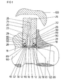
- FIG. 1 It is a section of the first high-pressure turbine stage a gas turbine consisting of an impeller 110 and a stator 120 shown.
- the impeller 110 is in the radial direction from a jacket ring surrounded by several, in the circumferential direction strung together jacket segments 10 is constructed.
- Each jacket segment 10 is assigned to a carrier segment 20, which in is not shown in detail on a housing 100 is fixed.
- the support segment 20 is in a substantially radial direction from an air supply duct 26 penetrates through the cooling air from a not shown Cooling air supply is supplied.
- Cooling air supply is supplied.
- the air supply duct 26 opens into a continuous recess 24 in the circumferential direction, which is part of an air duct chamber 25.
- the air guide chamber 25 becomes radial limited on the inside by a guide segment 30.
- the leading segment 30 has a U-shaped basic shape with two webs 32, which designed in corresponding Engage guide grooves 22 of the carrier segment 20.
- the guide segment 30 is supported on two ribs Spacers 12, which run in the circumferential direction and in the radial Direction protruding on the back of the shell segment 10 are attached.
- a jacket cooling chamber 15 arises in the radial direction between the shell segment 10 and the Guide segment 30 a jacket cooling chamber 15.
- the guide segments 30 have a large number through openings 34 which provide a fluid connection between represent the air guide chamber 25 and the jacket cooling chamber 15 and the Training of cooling air jets serve.
- the carrier segment 20 and the jacket segment 10 have flange sections 28 or 18, which are surrounded by retaining clips 80 and thus that Connect the carrier segment 20 and the jacket segment 10 to one another.
- the retaining clips 80 have an approximately U-shaped cross-sectional profile with two axial webs 89, which in corresponding axial grooves 29, 19 of the support segment 20th or the shell segment 10 engage. This creates an axial aligned transition from the carrier segment 20 to the jacket segment 10.
- Sealing elements 90 are in corner areas between the retaining clips 80 on the one hand and the flange portions 28 of the support segment 20 and Flange sections 18 of the shell segment 10, on the other hand, used to form a largely pressure-tight seal between the air-guiding areas, in particular the jacket cooling chamber 15 and the air duct chamber 25 and the surrounding area.
- the guide segments 30 are for forming in the circumferential direction continuous air-guiding channels overlapping.
- two abutting guide segments 30 are arranged such that there is an overlap area 38.
- the leading segments are 30 each shaped at one end so that it fits into the adjacent one Guide segment 30 can be inserted.
- the outer contour gives way slightly backwards, so that a kind Leadership results.
- the cooling air supplied via the air duct 26 acts on the guide segment 30 and presses it radially inward against the ribs 12 of the Sheath segment 10.
- a permanent pressure supply creates a pressure difference maintained between the air guide chamber 25 and the jacket cooling chamber 15, so that the guide segment 30 is securely fixed during operation.
- the maintenance of the pressure difference is required in order to to achieve the desired impingement cooling by cooling air jets, which are caused by the Through openings 34 are generated.
Landscapes
- Engineering & Computer Science (AREA)
- Mechanical Engineering (AREA)
- General Engineering & Computer Science (AREA)
- Turbine Rotor Nozzle Sealing (AREA)
Applications Claiming Priority (3)
| Application Number | Priority Date | Filing Date | Title |
|---|---|---|---|
| DE19855130A DE19855130A1 (de) | 1998-11-30 | 1998-11-30 | Kühlbarer Mantel einer Gasturbine oder dergleichen |
| DE19855130 | 1998-11-30 | ||
| US09/450,728 US6322320B1 (en) | 1998-11-30 | 1999-11-30 | Coolable casing of a gas turbine or the like |
Publications (3)
| Publication Number | Publication Date |
|---|---|
| EP1006264A2 true EP1006264A2 (fr) | 2000-06-07 |
| EP1006264A3 EP1006264A3 (fr) | 2003-10-22 |
| EP1006264B1 EP1006264B1 (fr) | 2005-01-05 |
Family
ID=26050451
Family Applications (1)
| Application Number | Title | Priority Date | Filing Date |
|---|---|---|---|
| EP99811095A Expired - Lifetime EP1006264B1 (fr) | 1998-11-30 | 1999-11-26 | Virole refroidissable pour turbomachine |
Country Status (4)
| Country | Link |
|---|---|
| US (1) | US6322320B1 (fr) |
| EP (1) | EP1006264B1 (fr) |
| JP (1) | JP4489882B2 (fr) |
| DE (1) | DE19855130A1 (fr) |
Cited By (1)
| Publication number | Priority date | Publication date | Assignee | Title |
|---|---|---|---|---|
| DE102013216392A1 (de) * | 2013-08-19 | 2015-02-19 | MTU Aero Engines AG | Vorrichtung und Verfahren zur Regelung der Temperatur eines Bauteils einer Strömungsmaschine |
Families Citing this family (10)
| Publication number | Priority date | Publication date | Assignee | Title |
|---|---|---|---|---|
| EP1329594A1 (fr) * | 2002-01-17 | 2003-07-23 | Siemens Aktiengesellschaft | Réglage du jeu d'aubes pour une turbine à gas |
| JP4969687B2 (ja) * | 2008-03-31 | 2012-07-04 | 三菱重工業株式会社 | スクロール本体の保温構造 |
| US8079804B2 (en) * | 2008-09-18 | 2011-12-20 | Siemens Energy, Inc. | Cooling structure for outer surface of a gas turbine case |
| US8092161B2 (en) | 2008-09-24 | 2012-01-10 | Siemens Energy, Inc. | Thermal shield at casing joint |
| US8128344B2 (en) * | 2008-11-05 | 2012-03-06 | General Electric Company | Methods and apparatus involving shroud cooling |
| US9255524B2 (en) * | 2012-12-20 | 2016-02-09 | United Technologies Corporation | Variable outer air seal fluid control |
| US9494081B2 (en) | 2013-05-09 | 2016-11-15 | Siemens Aktiengesellschaft | Turbine engine shutdown temperature control system with an elongated ejector |
| US10975721B2 (en) | 2016-01-12 | 2021-04-13 | Pratt & Whitney Canada Corp. | Cooled containment case using internal plenum |
| FR3082872B1 (fr) * | 2018-06-25 | 2021-06-04 | Safran Aircraft Engines | Dispositif de refroidissement d'un carter de turbomachine |
| DE102023121051A1 (de) * | 2023-08-08 | 2025-02-13 | MTU Aero Engines AG | Kühlbares Turbinenmodul und erwärmbares Verdichtermodul für eine Strömungsmaschine, sowie Strömungsmaschine |
Citations (1)
| Publication number | Priority date | Publication date | Assignee | Title |
|---|---|---|---|---|
| EP0516322B1 (fr) | 1991-05-20 | 1995-11-08 | General Electric Company | Refroidissement pour anneau de stator de turbine à gaz |
Family Cites Families (10)
| Publication number | Priority date | Publication date | Assignee | Title |
|---|---|---|---|---|
| US4013376A (en) * | 1975-06-02 | 1977-03-22 | United Technologies Corporation | Coolable blade tip shroud |
| GB2047354B (en) * | 1979-04-26 | 1983-03-30 | Rolls Royce | Gas turbine engines |
| US4337016A (en) * | 1979-12-13 | 1982-06-29 | United Technologies Corporation | Dual wall seal means |
| US4551064A (en) * | 1982-03-05 | 1985-11-05 | Rolls-Royce Limited | Turbine shroud and turbine shroud assembly |
| FR2548733B1 (fr) * | 1983-07-07 | 1987-07-10 | Snecma | Dispositif d'etancheite d'aubages mobiles de turbomachine |
| US4642024A (en) * | 1984-12-05 | 1987-02-10 | United Technologies Corporation | Coolable stator assembly for a rotary machine |
| US4921401A (en) * | 1989-02-23 | 1990-05-01 | United Technologies Corporation | Casting for a rotary machine |
| US5116199A (en) * | 1990-12-20 | 1992-05-26 | General Electric Company | Blade tip clearance control apparatus using shroud segment annular support ring thermal expansion |
| US5167488A (en) * | 1991-07-03 | 1992-12-01 | General Electric Company | Clearance control assembly having a thermally-controlled one-piece cylindrical housing for radially positioning shroud segments |
| DE19619438B4 (de) * | 1996-05-14 | 2005-04-21 | Alstom | Wärmestausegment für eine Turbomaschine |
-
1998
- 1998-11-30 DE DE19855130A patent/DE19855130A1/de not_active Ceased
-
1999
- 1999-11-26 EP EP99811095A patent/EP1006264B1/fr not_active Expired - Lifetime
- 1999-11-30 JP JP34084399A patent/JP4489882B2/ja not_active Expired - Fee Related
- 1999-11-30 US US09/450,728 patent/US6322320B1/en not_active Expired - Lifetime
Patent Citations (1)
| Publication number | Priority date | Publication date | Assignee | Title |
|---|---|---|---|---|
| EP0516322B1 (fr) | 1991-05-20 | 1995-11-08 | General Electric Company | Refroidissement pour anneau de stator de turbine à gaz |
Cited By (1)
| Publication number | Priority date | Publication date | Assignee | Title |
|---|---|---|---|---|
| DE102013216392A1 (de) * | 2013-08-19 | 2015-02-19 | MTU Aero Engines AG | Vorrichtung und Verfahren zur Regelung der Temperatur eines Bauteils einer Strömungsmaschine |
Also Published As
| Publication number | Publication date |
|---|---|
| US6322320B1 (en) | 2001-11-27 |
| EP1006264A3 (fr) | 2003-10-22 |
| JP4489882B2 (ja) | 2010-06-23 |
| EP1006264B1 (fr) | 2005-01-05 |
| JP2000192802A (ja) | 2000-07-11 |
| DE19855130A1 (de) | 2000-05-31 |
Similar Documents
| Publication | Publication Date | Title |
|---|---|---|
| DE602004011859T2 (de) | Vorrichtung für die Regelung von Spalten in einer Gasturbine | |
| EP1048822B1 (fr) | Bouclier thermique pour turbine à gaz | |
| EP1006264B1 (fr) | Virole refroidissable pour turbomachine | |
| DE19812380A1 (de) | Träger für Dichtung mit geringer Wärmeausdehnung | |
| DE2907769A1 (de) | Mantelhalterung mit aufprallkuehlung | |
| EP1418319A1 (fr) | Turbine à Gaz | |
| EP1443275A1 (fr) | Chambre de combustion | |
| EP1656497B1 (fr) | Diffuseur situe entre le compresseur et la chambre de combustion d'une turbine a gaz | |
| EP1022437A1 (fr) | Elément de construction à l'usage d'une machine thermique | |
| DE1601557A1 (de) | Stroemungsmittelgekuehlte Statoranordnung | |
| EP1409926A1 (fr) | Dispositif de refroidissement par choc | |
| EP3477063A1 (fr) | Turbomachine comprenant un ensemble de refroidissement par impact spécifique | |
| EP0040267B1 (fr) | Stator refroidi pour turbines | |
| EP2148045A1 (fr) | Section de boîtier pour une turbine à gaz | |
| EP0838595A2 (fr) | Support pour aube pour un compresseur | |
| EP1165942B1 (fr) | Turbomachine avec un systeme d'elements de paroi pouvant etre refroidi et procede de refroidissement d'un systeme d'elements de paroi | |
| DE4242721A1 (de) | Gasturbinenbrennkammer | |
| EP2206885A1 (fr) | Turbine à gaz | |
| EP1848904B1 (fr) | Element d'etancheite s'utilisant dans une turbomachine | |
| EP3256783B1 (fr) | Carter guidant des gaz chauds | |
| EP2347100B1 (fr) | Turbine à gaz avec insert de refroidissement | |
| DE3011503A1 (de) | Verdichteranordnung fuer ein axialgasturbinentriebwerk | |
| DE112014006619B4 (de) | Gasturbinenbrennkammer und mit selbiger versehene Gasturbine | |
| DE3424141A1 (de) | Luftspeicher-gasturbine | |
| EP2218882A1 (fr) | Système de support d'aube directrice |
Legal Events
| Date | Code | Title | Description |
|---|---|---|---|
| PUAI | Public reference made under article 153(3) epc to a published international application that has entered the european phase |
Free format text: ORIGINAL CODE: 0009012 |
|
| AK | Designated contracting states |
Kind code of ref document: A2 Designated state(s): AT BE CH CY DE DK ES FI FR GB GR IE IT LI LU MC NL PT SE |
|
| AX | Request for extension of the european patent |
Free format text: AL;LT;LV;MK;RO;SI |
|
| RAP1 | Party data changed (applicant data changed or rights of an application transferred) |
Owner name: ALSTOM |
|
| RAP1 | Party data changed (applicant data changed or rights of an application transferred) |
Owner name: ALSTOM (SWITZERLAND) LTD |
|
| PUAL | Search report despatched |
Free format text: ORIGINAL CODE: 0009013 |
|
| AK | Designated contracting states |
Kind code of ref document: A3 Designated state(s): AT BE CH CY DE DK ES FI FR GB GR IE IT LI LU MC NL PT SE |
|
| AX | Request for extension of the european patent |
Extension state: AL LT LV MK RO SI |
|
| RIC1 | Information provided on ipc code assigned before grant |
Ipc: 7F 01D 25/24 B Ipc: 7F 01D 25/12 B Ipc: 7F 01D 11/08 B Ipc: 7F 01D 11/24 A |
|
| RAP1 | Party data changed (applicant data changed or rights of an application transferred) |
Owner name: ALSTOM TECHNOLOGY LTD |
|
| GRAP | Despatch of communication of intention to grant a patent |
Free format text: ORIGINAL CODE: EPIDOSNIGR1 |
|
| 17P | Request for examination filed |
Effective date: 20040413 |
|
| AKX | Designation fees paid |
Designated state(s): DE GB |
|
| GRAS | Grant fee paid |
Free format text: ORIGINAL CODE: EPIDOSNIGR3 |
|
| GRAA | (expected) grant |
Free format text: ORIGINAL CODE: 0009210 |
|
| AK | Designated contracting states |
Kind code of ref document: B1 Designated state(s): DE GB |
|
| REG | Reference to a national code |
Ref country code: GB Ref legal event code: FG4D Free format text: NOT ENGLISH |
|
| REG | Reference to a national code |
Ref country code: IE Ref legal event code: FG4D Free format text: GERMAN |
|
| REF | Corresponds to: |
Ref document number: 59911401 Country of ref document: DE Date of ref document: 20050210 Kind code of ref document: P |
|
| GBT | Gb: translation of ep patent filed (gb section 77(6)(a)/1977) |
Effective date: 20050412 |
|
| PLBE | No opposition filed within time limit |
Free format text: ORIGINAL CODE: 0009261 |
|
| STAA | Information on the status of an ep patent application or granted ep patent |
Free format text: STATUS: NO OPPOSITION FILED WITHIN TIME LIMIT |
|
| 26N | No opposition filed |
Effective date: 20051006 |
|
| REG | Reference to a national code |
Ref country code: GB Ref legal event code: FG4D Free format text: NOT ENGLISH |
|
| REG | Reference to a national code |
Ref country code: DE Ref legal event code: R082 Ref document number: 59911401 Country of ref document: DE Representative=s name: ROESLER, UWE, DIPL.-PHYS.UNIV., DE Ref country code: DE Ref legal event code: R081 Ref document number: 59911401 Country of ref document: DE Owner name: ANSALDO ENERGIA IP UK LIMITED, GB Free format text: FORMER OWNER: ALSTOM TECHNOLOGY LTD., BADEN, CH Ref country code: DE Ref legal event code: R081 Ref document number: 59911401 Country of ref document: DE Owner name: GENERAL ELECTRIC TECHNOLOGY GMBH, CH Free format text: FORMER OWNER: ALSTOM TECHNOLOGY LTD., BADEN, CH |
|
| REG | Reference to a national code |
Ref country code: DE Ref legal event code: R082 Ref document number: 59911401 Country of ref document: DE Representative=s name: ROESLER, UWE, DIPL.-PHYS.UNIV., DE Ref country code: DE Ref legal event code: R081 Ref document number: 59911401 Country of ref document: DE Owner name: ANSALDO ENERGIA IP UK LIMITED, GB Free format text: FORMER OWNER: GENERAL ELECTRIC TECHNOLOGY GMBH, BADEN, CH |
|
| REG | Reference to a national code |
Ref country code: GB Ref legal event code: 732E Free format text: REGISTERED BETWEEN 20170824 AND 20170830 |
|
| PGFP | Annual fee paid to national office [announced via postgrant information from national office to epo] |
Ref country code: DE Payment date: 20171121 Year of fee payment: 19 |
|
| PGFP | Annual fee paid to national office [announced via postgrant information from national office to epo] |
Ref country code: GB Payment date: 20171123 Year of fee payment: 19 |
|
| REG | Reference to a national code |
Ref country code: DE Ref legal event code: R119 Ref document number: 59911401 Country of ref document: DE |
|
| GBPC | Gb: european patent ceased through non-payment of renewal fee |
Effective date: 20181126 |
|
| PG25 | Lapsed in a contracting state [announced via postgrant information from national office to epo] |
Ref country code: DE Free format text: LAPSE BECAUSE OF NON-PAYMENT OF DUE FEES Effective date: 20190601 |
|
| PG25 | Lapsed in a contracting state [announced via postgrant information from national office to epo] |
Ref country code: GB Free format text: LAPSE BECAUSE OF NON-PAYMENT OF DUE FEES Effective date: 20181126 |