EP1006301B1 - Joint à brosse avec poils coudés - Google Patents
Joint à brosse avec poils coudés Download PDFInfo
- Publication number
- EP1006301B1 EP1006301B1 EP99122735A EP99122735A EP1006301B1 EP 1006301 B1 EP1006301 B1 EP 1006301B1 EP 99122735 A EP99122735 A EP 99122735A EP 99122735 A EP99122735 A EP 99122735A EP 1006301 B1 EP1006301 B1 EP 1006301B1
- Authority
- EP
- European Patent Office
- Prior art keywords
- bristles
- brush seal
- rotor
- sections
- angled
- Prior art date
- Legal status (The legal status is an assumption and is not a legal conclusion. Google has not performed a legal analysis and makes no representation as to the accuracy of the status listed.)
- Expired - Lifetime
Links
- 238000005452 bending Methods 0.000 claims description 22
- 238000007789 sealing Methods 0.000 claims description 16
- 230000000694 effects Effects 0.000 description 12
- 238000009434 installation Methods 0.000 description 7
- 230000002093 peripheral effect Effects 0.000 description 5
- 230000015572 biosynthetic process Effects 0.000 description 2
- 230000001680 brushing effect Effects 0.000 description 1
- 230000005465 channeling Effects 0.000 description 1
- 230000000052 comparative effect Effects 0.000 description 1
- 230000001447 compensatory effect Effects 0.000 description 1
- 230000001419 dependent effect Effects 0.000 description 1
- 230000002542 deteriorative effect Effects 0.000 description 1
- 238000006073 displacement reaction Methods 0.000 description 1
- 230000007704 transition Effects 0.000 description 1
Images

Classifications
-
- F—MECHANICAL ENGINEERING; LIGHTING; HEATING; WEAPONS; BLASTING
- F16—ENGINEERING ELEMENTS AND UNITS; GENERAL MEASURES FOR PRODUCING AND MAINTAINING EFFECTIVE FUNCTIONING OF MACHINES OR INSTALLATIONS; THERMAL INSULATION IN GENERAL
- F16J—PISTONS; CYLINDERS; SEALINGS
- F16J15/00—Sealings
- F16J15/16—Sealings between relatively-moving surfaces
- F16J15/32—Sealings between relatively-moving surfaces with elastic sealings, e.g. O-rings
- F16J15/3284—Sealings between relatively-moving surfaces with elastic sealings, e.g. O-rings characterised by their structure; Selection of materials
- F16J15/3288—Filamentary structures, e.g. brush seals
Definitions
- the invention relates to a brush seal with angled bristles, for Sealing a rotor against a stator comprising a support plate a longitudinal section and an angled support section and bristles with shaft sections and angled bristle sections whose Run the ends against the sealing surface of the rotor.
- the bristles are angled to reduce the radial overall length.
- a stop located in the area of the shaft sections of the bristles provided that acts as a bending edge when the elastic bristles result an eccentricity of the rotor can be deflected. That way the stiffness of the bristles can be adjusted without an impermissibly large radial installation space.
- the object of the present invention is a brush seal to improve with angled bristles so that the best possible Sealing effect is achieved without the so-called “hang up effect", after which the bristle pack is pressed against the support plate when differential pressure is present will stick to it due to the frictional force.
- the solution to the problem is characterized in that there is a bending space between the shank sections of the bristles and the support plate is provided and between the angled bristle sections and the support section of the support plate has a gap over its entire length which closes when differential pressure is present.
- the advantage is that the setting that can be selected depending on the differential pressure the gap, the pressure in the bending space the pressure in front of the brush seal equivalent. That means almost all of the pressure drop across the angled bristle pack or the angled bristle sections takes place.
- the bristle pack is not in the way when pressurized brought a constraint that it is under great axial pressure on the support section is pressed, loses its elasticity and after a deflection of the Rotors sticks there.
- the angled bristle sections lay down at least in places or sections on the support section the support plate while closing the gap.
- the gap is preferably set such that in the shaft sections of the bristles no pressure loads or - when differential pressure is present tensions are present. Rather, the differential pressure as a tensile force in the Shank sections of the bristles added. In this way, the Pressure in the bending space the greater pressure in front of the brush seal, so that the shaft sections of the bristles do not experience any pressure load and at one Changes in the pressure level show a quasi-automatic reset effect.
- the pressure in the bending space which is still higher for a short time, presses the elastic bristles towards the sealing surface of the rotor, i.e. generally radially inward.
- the shaft sections are reversed the elastic bristles when the pressure rises initially from the sealing surface of the rotor, i.e. generally radially outward until a Pressure equalization.
- the bending free space preferably extends to an end edge of the longitudinal section the support plate.
- the solution to the problem is alternatively characterized in that the angled Bristle sections at an angle in the direction of the direction of rotation of the rotor are employed, the angle between 0 ° and 70 ° and highly preferred is between 40 ° and 50 °.
- a bending space is provided so that the restoring effect of the bristles changing pressures and deflections of the rotor overlaid by bending and torsion is generated.
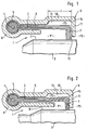
- FIG. 1 shows an embodiment of a brush seal, generally designated 1, the two rooms with different pressures P1, P2 between a rotationally symmetrical indicated with its peripheral surface U.
- Rotor 2 and a stator not shown, e.g. one housing, one Gas turbine, e.g. of an aircraft engine, seals.
- the pressure P1 is higher than the pressure P2.
- the brush seal 1 is in Fig. 1 without pressurization shown.
- the free ends of the bristles or bristle pack 3 of the Brush seal 1 run against the peripheral surface U of the rotor 2.
- the bristles 3 are wound around a core 4 and held in a retaining ring 5 or positioned.
- the type of attachment of the bristles 3 is not important in the present case and can be done in other ways.
- the bristle pack or the bristles 3 have shaft sections 6 and angled sections Bristle sections 7. Extend in the present installation position the shaft sections 6 of the bristles 3 in the axial direction of the gas turbine.
- the Angle between the shaft sections 6 and the angled bristle sections In the present case, 7 is approximately 90 °, so that the angled bristle section 7 lies essentially in a radial plane.
- the retaining ring 5 is in one positioned overall with 8 housing of the brush seal 1.
- the housing 8 comprises a support plate 9 with a substantially longitudinal section extending in the direction of the shaft section 6 of the bristles 3 10 and an angled support section 11.
- the shape of the Housing 8, the support plate 9 and a front plate, not described in detail influence the function of the brush seal 1 and are depending on Use case designed.
- the free ends of the angled bristle sections 7 are in contact via the support section 11 of the support plate 9 the peripheral surface U of the rotor 2 before.
- a bending space 13 is provided between the bristles 3 and the support plate 9.
- the bending space 13 extends up to the transition between the longitudinal section 10 and the support section 11 of the support plate 9 forming end edge 14.
- the shaft sections 6 of the bristles 3 can in the Bending free space 13 are deflected so as to be relatively rigid to keep short, angled bristle sections 7 within reasonable limits and depending on the length L of the deflectable part of the shaft sections To be able to adjust 6 of the bristles 3.
- the length L of the bending space 13 starting from the support section 11 of the support plate 9 may well continue extend in the direction of the retaining ring 5 of the bristles 3 than the present one Embodiment is shown.
- the support plate 9 has a gap 12.
- the size of the gap 12 becomes dependent of the pressure difference applied to the brush seal 1 during operation set so that it is ensured that the shaft portions 6 of the Bristles 3 with pressure difference not under pressure in the shaft sections 6 in a forced position against the support section 11 or its inner surface can be pressed.
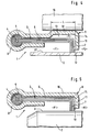
- Fig. 2 shows a schematic side view of a brush seal, in which the Bristles 3 due to an increase in pressure in the room higher pressure P1 or as a result a rotor / housing displacement are deflected.
- the pressure P3 in the bending space 13 is higher than the pressure P1 in the space Pressure.
- FIG. 3 shows another installation position of a brush seal 1, in which the longitudinal section 10 of the support plate 9 and the shaft sections 6 of the Bristles 3 extend essentially in a radial plane of the gas turbine and the free ends of the angled bristle sections 7 against a radially aligned face sealing surface 15 of the rotor 2 run.
- the support section 11 of the support plate 9 and the angled bristle sections 7 of the bristles 3 run in this embodiment essentially in the axial direction Gas turbine.
- the described pressure compensation movement of the bristles 3 through the previously set size of the gap 12 when the pressure difference changes between the higher pressure space P1 and the lower space Pressure P2 is done in the same way.
- the brush seal 1 with angled bristle sections 7 can be used in all use their designs in different installation positions and is both suitable for stationary gas turbines as well as for aircraft engines. by virtue of the angled one that extends generally in the radial direction Bristle sections 7, the brush seal 1 in both directions of rotation of the rotor 2 are operated.
- Fig. 4 shows an alternative installation position of an embodiment of the invention Brush seal 1 against a circumferential surface U 'of a radial rotor 2 arranged on the outside seals, for example a cylindrical one in the case of a roller Ring component can be. 4, the conditions are without pressurization shown.
- the brush seal 1 is on an inside Stator 16 arranged so that the angled bristle sections 7 in essentially in the radial direction to the outside or - when the angled Bristle sections 7 in the direction of rotation of the rotor - at an angle between Extend 0 ° and 70 ° to the radial direction.
- the setting described above the gap 12 takes place in a corresponding manner.
- Brush seal 1 are the angled bristle sections 7 at an angle of about 45 ° to the radial direction in the direction of rotation of the rotor.
- a Deflection of the rotor 2 is consequently the shaft sections 6 of the Bristles 3 twisted, a so-called channel formation for through the bristle pack 3 flowing air is avoided.
- due to the torsion generates large restoring force, so that the angled bristle sections 7 after the deflection and not on the support section 11 of the Support plate 9 stick. Due to the effects described, a achieve a significant improvement in the sealing effect of the brush seal 1.
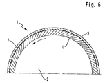
- Fig. 6 shows a schematic front view in section, in which half of the Brush seal 1 according to the embodiment of FIG. 5 is shown.
- the support section 11 of the support plate 9 is omitted or only hinted at.
- the angled bristle sections 7 in the direction of the direction of rotation, which is marked with an arrow is set at an angle of approximately 45 °.
- the angled bristle sections 7 are underneath Torsion of the shaft sections 6. This measure will result in the one described above Channel formation avoided. There is also a large restoring force due to the torsion.
- the angled bristle sections 7 in one another Angles from 0 ° to 70 ° with respect to the radial direction in the direction of rotation of the rotor be employed. With such a position, the shaft sections 6 the bristles 3 with radial deflection of the angled bristle sections 7, e.g. due to a deflection of the rotor 2, twisted and thereby unfold a large restoring force, so that here too the angled bristle sections 7 not deteriorating the sealing effect on the support section 11 of the support plate 9 stick.
- the design of the brush seal 1 with employed, angled bristle sections 7 can both with and without bending space 13. In a version with Bending free space 13 therefore occurs when the rotor 2 is deflected of bending and torsion of the shaft sections 6 of the bristles 3.
Landscapes
- Engineering & Computer Science (AREA)
- General Engineering & Computer Science (AREA)
- Mechanical Engineering (AREA)
- Sealing Devices (AREA)
- Turbine Rotor Nozzle Sealing (AREA)
Claims (10)
- Joint à brosse comprenant des poils coudés, servant à rendre étanche un rotor (2) par rapport à un stator, comprenant une plaque d'appui (9) comportant une partie longitudinale (10) et une partie d'appui (11), et des poils (3) comportant des parties (6) formant la tige et des parties de poils coudées (7) par rapport à ces parties formant la tige, parties de poils dont les extrémités s'appliquent contre la surface d'étanchéité du rotor (2),
caractérisé en ce qu'il est prévu un espace libre de flexion (13) placé entre les parties (6) formant la tige des poils (3), et la plaque d'appui (9), et un intervalle (12) existe entre les parties de poils coudées (7) et la partie d'appui (11) de la plaque d'appui (9), lequel intervalle, qui s'étend sur toute la longueur de la partie d'appui, se ferme en cas de pression différentielle de contact. - Joint à brosse selon la revendication 1, caractérisé en ce que l'intervalle (12) est réglé de manière telle, qu'il n'y a aucune contrainte de pression dans les parties (6) formant la tige des poils (3), en cas de pression différentielle de contact.
- Joint à brosse selon la revendication 1 ou 2, caractérisé en ce que l'espace libre de flexion (13) s'étend jusqu'au bord d'extrémité (14) de la partie longitudinale (10) de la plaque d'appui (9).
- Joint à brosse comportant des poils coudés, servant à rendre étanche un rotor (2) par rapport à un stator, comprenant une plaque d'appui (9) comportant une partie longitudinale (10) et une partie d'appui (11), et des poils (3) comportant des parties (6) formant la tige et des parties de poils coudées (7) par rapport à ces parties formant la tige, parties de poils dont les extrémités s'appliquent contre la surface d'étanchéité du rotor (2), caractérisé en ce que les parties de poils coudées (7) sont réglées suivant un angle formé en direction du sens de rotation du rotor.
- Joint à brosse selon la revendication 4, caractérisé en ce que l'angle est compris entre 0° et 70°.
- Joint à brosse selon la revendication 4 ou 5, caractérisé en ce qu'il est prévu un espace libre de flexion (13) placé entre les parties (6) formant la tige des poils (3), et la plaque d'appui (9).
- Joint à brosse selon l'une quelconque ou plusieurs des revendications précédentes, caractérisé en ce que les parties (6) formant la tige des poils (3) sont plus longues que les parties de poils coudées (7).
- Joint à brosse selon l'une quelconque ou plusieurs des revendications précédentes, caractérisé en ce que les poils (3), par leurs extrémités libres, assurent l'étanchéité en s'appliquant contre un rotor (2) placé à l'intérieur.
- Joint à brosse selon l'une quelconque ou plusieurs des revendications 1 à 7, caractérisé en ce que les poils (3), par leurs extrémités libres, assurent l'étanchéité en s'appliquant contre un rotor (2) placé à l'extérieur.
- Joint à brosse selon la revendication 9, caractérisé en ce que le rotor (2) est un corps annulaire cylindrique.
Applications Claiming Priority (2)
| Application Number | Priority Date | Filing Date | Title |
|---|---|---|---|
| DE19855742A DE19855742C1 (de) | 1998-12-03 | 1998-12-03 | Bürstendichtung mit abgewinkelten Borsten |
| DE19855742 | 1998-12-03 |
Publications (2)
| Publication Number | Publication Date |
|---|---|
| EP1006301A1 EP1006301A1 (fr) | 2000-06-07 |
| EP1006301B1 true EP1006301B1 (fr) | 2004-05-12 |
Family
ID=7889814
Family Applications (1)
| Application Number | Title | Priority Date | Filing Date |
|---|---|---|---|
| EP99122735A Expired - Lifetime EP1006301B1 (fr) | 1998-12-03 | 1999-11-16 | Joint à brosse avec poils coudés |
Country Status (6)
| Country | Link |
|---|---|
| US (1) | US6352263B1 (fr) |
| EP (1) | EP1006301B1 (fr) |
| JP (1) | JP4616435B2 (fr) |
| CA (1) | CA2291467C (fr) |
| DE (2) | DE19855742C1 (fr) |
| ES (1) | ES2219981T3 (fr) |
Families Citing this family (33)
| Publication number | Priority date | Publication date | Assignee | Title |
|---|---|---|---|---|
| US6416647B1 (en) * | 1998-04-21 | 2002-07-09 | Applied Materials, Inc. | Electro-chemical deposition cell for face-up processing of single semiconductor substrates |
| US6258220B1 (en) * | 1998-11-30 | 2001-07-10 | Applied Materials, Inc. | Electro-chemical deposition system |
| DE19962316C2 (de) * | 1999-12-23 | 2002-07-18 | Mtu Aero Engines Gmbh | Bürstendichtung |
| DE10017643B4 (de) * | 2000-04-08 | 2005-10-20 | Mtu Aero Engines Gmbh | Dichtung in nicht-hermetischer Ausführung |
| US20100007093A1 (en) * | 2001-02-23 | 2010-01-14 | Grondahl Clayton M | Seal Assembly and Rotary Machine Containing Such Seal |
| US7578509B2 (en) * | 2001-02-23 | 2009-08-25 | Cmg Tech, Llc | Seal assembly and rotary machine containing such seal |
| US6644667B2 (en) * | 2001-02-23 | 2003-11-11 | Cmg Tech, Llc | Seal assembly and rotary machine containing such seal |
| JP4944312B2 (ja) * | 2001-06-29 | 2012-05-30 | イーグル工業株式会社 | ブラシシール装置 |
| JP3611811B2 (ja) | 2001-08-22 | 2005-01-19 | ティー・アンド・エム株式会社 | 高速回転体用シール材およびその使用方法ならびに現像装置 |
| GB0127643D0 (en) | 2001-11-17 | 2002-01-09 | Cross Mfg 1938 Company Ltd | A brush seal element |
| DE10163804B4 (de) * | 2001-12-22 | 2005-07-07 | Mtu Aero Engines Gmbh | Bürstendichtung |
| US20040118694A1 (en) * | 2002-12-19 | 2004-06-24 | Applied Materials, Inc. | Multi-chemistry electrochemical processing system |
| US6679500B1 (en) | 2002-09-25 | 2004-01-20 | Alstom (Switzerland) Ltd | Coal pulverizer brush seal assembly |
| US8199453B2 (en) * | 2003-03-17 | 2012-06-12 | Illinois Tool Works Inc. | Shaft current control brush ring assembly |
| US20050077182A1 (en) * | 2003-10-10 | 2005-04-14 | Applied Materials, Inc. | Volume measurement apparatus and method |
| FR2865012B1 (fr) * | 2004-01-12 | 2006-03-17 | Snecma Moteurs | Dispositif d'etancheite pour turbine haute-pression de turbomachine |
| GB2410533B (en) * | 2004-01-28 | 2006-02-08 | Rolls Royce Plc | Sealing arrangement |
| US20070278093A1 (en) * | 2006-06-02 | 2007-12-06 | Barnard Michael P | Electrical conductive contact ring for electroplating or electrodeposition |
| DE102006049634A1 (de) * | 2006-10-20 | 2008-04-24 | Mtu Aero Engines Gmbh | Dichtungsanordnung |
| US8596973B2 (en) * | 2009-12-07 | 2013-12-03 | Cmg Tech, Llc | Leaf seal assembly including polymer member and rotary machine containing such seal assembly |
| US8317464B2 (en) * | 2010-02-16 | 2012-11-27 | General Electric Company | Reverse flow tolerant spring activated brush seal |
| US9121297B2 (en) | 2011-03-28 | 2015-09-01 | General Electric Company | Rotating brush seal |
| US9255486B2 (en) | 2011-03-28 | 2016-02-09 | General Electric Company | Rotating brush seal |
| US8632075B2 (en) * | 2011-08-08 | 2014-01-21 | General Electric Company | Seal assembly and method for flowing hot gas in a turbine |
| GB201202104D0 (en) * | 2012-02-08 | 2012-03-21 | Rolls Royce Plc | Leaf seal |
| US9540942B2 (en) | 2012-04-13 | 2017-01-10 | General Electric Company | Shaft sealing system for steam turbines |
| US9587505B2 (en) | 2013-12-05 | 2017-03-07 | General Electric Company | L brush seal for turbomachinery application |
| US9322287B2 (en) * | 2014-06-03 | 2016-04-26 | General Electric Company | Brush seal for turbine |
| US11035470B2 (en) | 2018-04-05 | 2021-06-15 | Raytheon Technologies Corporation | Multi-plane brush seal |
| US10662797B2 (en) | 2018-04-05 | 2020-05-26 | Raytheon Technologies Corporation | Multi-plane brush seal |
| US11261971B2 (en) * | 2019-11-11 | 2022-03-01 | Raytheon Technologies Corporation | Double angled brush seal |
| CN114635757B (zh) * | 2022-02-23 | 2023-12-12 | 潍柴动力股份有限公司 | 转子密封装置 |
| US20260015947A1 (en) * | 2024-07-11 | 2026-01-15 | Rtx Corporation | Brush seal assembly with metal clip |
Family Cites Families (10)
| Publication number | Priority date | Publication date | Assignee | Title |
|---|---|---|---|---|
| JPS5717U (fr) * | 1980-05-30 | 1982-01-05 | ||
| GB2140674A (en) * | 1983-04-27 | 1984-12-05 | Schlegel | Angled bristle strips and methods of manufacture |
| US4779904A (en) * | 1986-10-31 | 1988-10-25 | Rich Christopher K | Couplings for connecting vehicle exhaust tail pipes to exhaust conduits for removing vehicle exhaust gases |
| GB2212228B (en) * | 1987-11-13 | 1991-08-07 | Rolls Royce Plc | Enhanced performance brush seals |
| US5110033A (en) * | 1991-02-21 | 1992-05-05 | United Technologies Corporation | Segmented brush seal |
| ATE238509T1 (de) * | 1995-10-05 | 2003-05-15 | Sealol | Bürstendichtung mit einer biegsamen frontscheibe |
| DE19613510C1 (de) * | 1996-04-04 | 1997-04-24 | Mtu Muenchen Gmbh | Bürstendichtung mit einem von Borstenbündeln umschlungenen Kernring |
| DE19618475B4 (de) * | 1996-05-08 | 2005-10-20 | Mtu Aero Engines Gmbh | Bürstendichtung |
| JP3382802B2 (ja) * | 1997-01-13 | 2003-03-04 | 三菱重工業株式会社 | 軸シール |
| DE19712088C2 (de) * | 1997-03-22 | 1999-06-24 | Mtu Muenchen Gmbh | Bürstendichtung mit in Umfangsrichtung schräg gestellten Borsten |
-
1998
- 1998-12-03 DE DE19855742A patent/DE19855742C1/de not_active Expired - Fee Related
-
1999
- 1999-11-16 DE DE59909465T patent/DE59909465D1/de not_active Expired - Lifetime
- 1999-11-16 EP EP99122735A patent/EP1006301B1/fr not_active Expired - Lifetime
- 1999-11-16 ES ES99122735T patent/ES2219981T3/es not_active Expired - Lifetime
- 1999-12-02 CA CA002291467A patent/CA2291467C/fr not_active Expired - Fee Related
- 1999-12-03 JP JP34514899A patent/JP4616435B2/ja not_active Expired - Fee Related
- 1999-12-03 US US09/454,193 patent/US6352263B1/en not_active Expired - Lifetime
Also Published As
| Publication number | Publication date |
|---|---|
| CA2291467A1 (fr) | 2000-06-03 |
| DE19855742C1 (de) | 2000-09-14 |
| EP1006301A1 (fr) | 2000-06-07 |
| DE59909465D1 (de) | 2004-06-17 |
| ES2219981T3 (es) | 2004-12-01 |
| CA2291467C (fr) | 2008-07-22 |
| JP4616435B2 (ja) | 2011-01-19 |
| JP2000170922A (ja) | 2000-06-23 |
| US6352263B1 (en) | 2002-03-05 |
Similar Documents
| Publication | Publication Date | Title |
|---|---|---|
| EP1006301B1 (fr) | Joint à brosse avec poils coudés | |
| DE19962316C2 (de) | Bürstendichtung | |
| DE69915587T2 (de) | Ineinanderschiebbare brückendichtung | |
| DE19720649C2 (de) | Bürstendichtung | |
| DE3836474C2 (de) | Bürstendichtung | |
| DE69828255T2 (de) | Dichtungsstruktur für gasturbinen | |
| EP3315728B1 (fr) | Palier amorti d'aube directrice | |
| EP2271827B1 (fr) | Turbomachine avec piston d'équilibrage de poussée | |
| EP1146266A2 (fr) | Joint à brosses | |
| DE60123740T2 (de) | Drehmaschine mit einer Bürstendichtung für eine Lagerbohrung | |
| DE102011052347A1 (de) | Schwimmende Packungsringanordnung | |
| DE2556992B1 (de) | Wellendichtring | |
| DE102012102625A1 (de) | Rotationsbürstendichtung | |
| EP1779008B1 (fr) | Ensemble d' etanche ite | |
| EP1224381B1 (fr) | Dispositif pour compenser la poussee axiale dans des turbomachines | |
| DE102016223867A1 (de) | Turbomaschinen-Dichtungsanordnung | |
| DE4425344C2 (de) | Drehschieber mit mindestens einem Axialnadeldrehkranz als drehbewegliches Lagerelement | |
| DE60305357T2 (de) | Bürstendichtung | |
| DE102020209287A1 (de) | Dichtungsanordnung mit großem Spiel | |
| DE2752445C2 (de) | Elastische Gelenkscheibe für Wellenkupplungen | |
| EP3748182B1 (fr) | Agencement de palier à rouleaux doté d'un dispositif d'étanchéité permettant d'étanchéifier la fente de palier | |
| WO2015074912A1 (fr) | Garniture d'étanchéité d'arbre et procédé pour la fabriquer | |
| EP1207324A2 (fr) | Joint d'étanchéité entre deux pièces d'un groupe rotatif, méthode pour la réalisation de la jonction étanche | |
| DE2844906C2 (de) | Dichtring, insbesondere für hydraulisch betätigte Zylinderkolben oder Kolbenstangen | |
| DE102019127890B3 (de) | Armatur mit Ausblassicherung |
Legal Events
| Date | Code | Title | Description |
|---|---|---|---|
| PUAI | Public reference made under article 153(3) epc to a published international application that has entered the european phase |
Free format text: ORIGINAL CODE: 0009012 |
|
| AK | Designated contracting states |
Kind code of ref document: A1 Designated state(s): CH DE ES FR GB IT LI |
|
| AX | Request for extension of the european patent |
Free format text: AL;LT;LV;MK;RO;SI |
|
| 17P | Request for examination filed |
Effective date: 20000726 |
|
| AKX | Designation fees paid |
Free format text: CH DE ES FR GB IT LI |
|
| RAP1 | Party data changed (applicant data changed or rights of an application transferred) |
Owner name: MTU AERO ENGINES GMBH |
|
| GRAP | Despatch of communication of intention to grant a patent |
Free format text: ORIGINAL CODE: EPIDOSNIGR1 |
|
| GRAS | Grant fee paid |
Free format text: ORIGINAL CODE: EPIDOSNIGR3 |
|
| GRAA | (expected) grant |
Free format text: ORIGINAL CODE: 0009210 |
|
| AK | Designated contracting states |
Kind code of ref document: B1 Designated state(s): CH DE ES FR GB IT LI |
|
| REG | Reference to a national code |
Ref country code: GB Ref legal event code: FG4D Free format text: NOT ENGLISH |
|
| REG | Reference to a national code |
Ref country code: CH Ref legal event code: EP |
|
| REG | Reference to a national code |
Ref country code: CH Ref legal event code: NV Representative=s name: ISLER & PEDRAZZINI AG |
|
| REF | Corresponds to: |
Ref document number: 59909465 Country of ref document: DE Date of ref document: 20040617 Kind code of ref document: P |
|
| GBT | Gb: translation of ep patent filed (gb section 77(6)(a)/1977) | ||
| REG | Reference to a national code |
Ref country code: ES Ref legal event code: FG2A Ref document number: 2219981 Country of ref document: ES Kind code of ref document: T3 |
|
| ET | Fr: translation filed | ||
| PLBE | No opposition filed within time limit |
Free format text: ORIGINAL CODE: 0009261 |
|
| STAA | Information on the status of an ep patent application or granted ep patent |
Free format text: STATUS: NO OPPOSITION FILED WITHIN TIME LIMIT |
|
| 26N | No opposition filed |
Effective date: 20050215 |
|
| REG | Reference to a national code |
Ref country code: CH Ref legal event code: PCAR Free format text: ISLER & PEDRAZZINI AG;POSTFACH 1772;8027 ZUERICH (CH) |
|
| PGFP | Annual fee paid to national office [announced via postgrant information from national office to epo] |
Ref country code: CH Payment date: 20121122 Year of fee payment: 14 |
|
| PGFP | Annual fee paid to national office [announced via postgrant information from national office to epo] |
Ref country code: ES Payment date: 20121127 Year of fee payment: 14 Ref country code: IT Payment date: 20121126 Year of fee payment: 14 |
|
| REG | Reference to a national code |
Ref country code: CH Ref legal event code: PL |
|
| PG25 | Lapsed in a contracting state [announced via postgrant information from national office to epo] |
Ref country code: LI Free format text: LAPSE BECAUSE OF NON-PAYMENT OF DUE FEES Effective date: 20131130 Ref country code: CH Free format text: LAPSE BECAUSE OF NON-PAYMENT OF DUE FEES Effective date: 20131130 |
|
| PG25 | Lapsed in a contracting state [announced via postgrant information from national office to epo] |
Ref country code: IT Free format text: LAPSE BECAUSE OF NON-PAYMENT OF DUE FEES Effective date: 20131116 |
|
| REG | Reference to a national code |
Ref country code: ES Ref legal event code: FD2A Effective date: 20150327 |
|
| PG25 | Lapsed in a contracting state [announced via postgrant information from national office to epo] |
Ref country code: ES Free format text: LAPSE BECAUSE OF NON-PAYMENT OF DUE FEES Effective date: 20131117 |
|
| REG | Reference to a national code |
Ref country code: FR Ref legal event code: PLFP Year of fee payment: 17 |
|
| PGFP | Annual fee paid to national office [announced via postgrant information from national office to epo] |
Ref country code: GB Payment date: 20151123 Year of fee payment: 17 Ref country code: DE Payment date: 20151119 Year of fee payment: 17 |
|
| PGFP | Annual fee paid to national office [announced via postgrant information from national office to epo] |
Ref country code: FR Payment date: 20151124 Year of fee payment: 17 |
|
| REG | Reference to a national code |
Ref country code: DE Ref legal event code: R119 Ref document number: 59909465 Country of ref document: DE |
|
| GBPC | Gb: european patent ceased through non-payment of renewal fee |
Effective date: 20161116 |
|
| REG | Reference to a national code |
Ref country code: FR Ref legal event code: ST Effective date: 20170731 |
|
| PG25 | Lapsed in a contracting state [announced via postgrant information from national office to epo] |
Ref country code: FR Free format text: LAPSE BECAUSE OF NON-PAYMENT OF DUE FEES Effective date: 20161130 |
|
| PG25 | Lapsed in a contracting state [announced via postgrant information from national office to epo] |
Ref country code: DE Free format text: LAPSE BECAUSE OF NON-PAYMENT OF DUE FEES Effective date: 20170601 Ref country code: GB Free format text: LAPSE BECAUSE OF NON-PAYMENT OF DUE FEES Effective date: 20161116 |