EP1006322A2 - Verfahren zum Einbringen von einem Erdwärmetauscher in das Erdreich sowie eine Erdwärmetauschervorrichtung - Google Patents
Verfahren zum Einbringen von einem Erdwärmetauscher in das Erdreich sowie eine Erdwärmetauschervorrichtung Download PDFInfo
- Publication number
- EP1006322A2 EP1006322A2 EP99204063A EP99204063A EP1006322A2 EP 1006322 A2 EP1006322 A2 EP 1006322A2 EP 99204063 A EP99204063 A EP 99204063A EP 99204063 A EP99204063 A EP 99204063A EP 1006322 A2 EP1006322 A2 EP 1006322A2
- Authority
- EP
- European Patent Office
- Prior art keywords
- head
- heat exchanger
- geothermal heat
- ground
- pipe
- Prior art date
- Legal status (The legal status is an assumption and is not a legal conclusion. Google has not performed a legal analysis and makes no representation as to the accuracy of the status listed.)
- Withdrawn
Links
- 238000000034 method Methods 0.000 title claims description 21
- 239000002689 soil Substances 0.000 claims abstract description 13
- 239000006163 transport media Substances 0.000 claims abstract description 5
- 230000008878 coupling Effects 0.000 claims description 14
- 238000010168 coupling process Methods 0.000 claims description 14
- 238000005859 coupling reaction Methods 0.000 claims description 14
- 239000007822 coupling agent Substances 0.000 claims description 3
- 238000004873 anchoring Methods 0.000 description 3
- 238000007639 printing Methods 0.000 description 3
- 244000089486 Phragmites australis subsp australis Species 0.000 description 2
- 239000000853 adhesive Substances 0.000 description 1
- 230000001070 adhesive effect Effects 0.000 description 1
- 239000004568 cement Substances 0.000 description 1
- 239000003795 chemical substances by application Substances 0.000 description 1
- 238000010276 construction Methods 0.000 description 1
- 238000005553 drilling Methods 0.000 description 1
- 239000012530 fluid Substances 0.000 description 1
- 239000003292 glue Substances 0.000 description 1
- 239000002184 metal Substances 0.000 description 1
- 229920003002 synthetic resin Polymers 0.000 description 1
- 239000000057 synthetic resin Substances 0.000 description 1
- XLYOFNOQVPJJNP-UHFFFAOYSA-N water Substances O XLYOFNOQVPJJNP-UHFFFAOYSA-N 0.000 description 1
Images

Classifications
-
- F—MECHANICAL ENGINEERING; LIGHTING; HEATING; WEAPONS; BLASTING
- F24—HEATING; RANGES; VENTILATING
- F24T—GEOTHERMAL COLLECTORS; GEOTHERMAL SYSTEMS
- F24T10/00—Geothermal collectors
- F24T10/10—Geothermal collectors with circulation of working fluids through underground channels, the working fluids not coming into direct contact with the ground
- F24T10/13—Geothermal collectors with circulation of working fluids through underground channels, the working fluids not coming into direct contact with the ground using tube assemblies suitable for insertion into boreholes in the ground, e.g. geothermal probes
- F24T10/15—Geothermal collectors with circulation of working fluids through underground channels, the working fluids not coming into direct contact with the ground using tube assemblies suitable for insertion into boreholes in the ground, e.g. geothermal probes using bent tubes; using tubes assembled with connectors or with return headers
-
- E—FIXED CONSTRUCTIONS
- E21—EARTH OR ROCK DRILLING; MINING
- E21B—EARTH OR ROCK DRILLING; OBTAINING OIL, GAS, WATER, SOLUBLE OR MELTABLE MATERIALS OR A SLURRY OF MINERALS FROM WELLS
- E21B23/00—Apparatus for displacing, setting, locking, releasing or removing tools, packers or the like in boreholes or wells
-
- F—MECHANICAL ENGINEERING; LIGHTING; HEATING; WEAPONS; BLASTING
- F24—HEATING; RANGES; VENTILATING
- F24T—GEOTHERMAL COLLECTORS; GEOTHERMAL SYSTEMS
- F24T10/00—Geothermal collectors
- F24T2010/50—Component parts, details or accessories
- F24T2010/53—Methods for installation
-
- Y—GENERAL TAGGING OF NEW TECHNOLOGICAL DEVELOPMENTS; GENERAL TAGGING OF CROSS-SECTIONAL TECHNOLOGIES SPANNING OVER SEVERAL SECTIONS OF THE IPC; TECHNICAL SUBJECTS COVERED BY FORMER USPC CROSS-REFERENCE ART COLLECTIONS [XRACs] AND DIGESTS
- Y02—TECHNOLOGIES OR APPLICATIONS FOR MITIGATION OR ADAPTATION AGAINST CLIMATE CHANGE
- Y02E—REDUCTION OF GREENHOUSE GAS [GHG] EMISSIONS, RELATED TO ENERGY GENERATION, TRANSMISSION OR DISTRIBUTION
- Y02E10/00—Energy generation through renewable energy sources
- Y02E10/10—Geothermal energy
Definitions
- the present invention relates to in the ground Introduction of a geothermal heat exchanger, which geothermal heat exchanger serves to extract heat from the surrounding floor and / or feed.
- geothermal heat exchangers to heat the ground withdraw, or feed straight to withdraw later being able to do is well known. So in countries like that Switzerland, Germany and Austria arranged geothermal heat exchangers, which to a depth of about 100-120 meters in the ground stuck. To place such geothermal heat exchangers in the ground, a hole is usually first drilled in the ground and then the heat exchanger is inserted into the drilled hole used.
- FR 2 492 043 describes it a process in which a long lance is buried in the ground is pressed in, which lance with a Roll, around which a flexible circulation line is provided. A strand of this line runs up through the interior of the lance the other run runs along the outside of the lance.
- the bottom of the lance has a hinge that rotates around it Cover that is pressed into the ground by the lance Bottom of the lance closes, and which is at the same time so large that a slit forms in the ground, in which the outside runs along the lance of the circulation line.
- the lid rotates around a hinge and moves with it the lance with high, the circulation line in the ground remains.
- the present invention is based on the object alternative method of placing a Geothermal heat exchanger, which method can be carried out in a simple manner and it enables the cost level for the application of Geothermal heat exchangers compared to the current state of the art lower, making it a major application of geothermal heat exchangers becomes economically attractive.
- the geothermal heat exchanger with cooperating coupling means provided in such a way are carried out that when lowering the geothermal heat exchanger in Hollow pipe brought into the ground automatically with a coupling the head is realized.
- the coupling agents can, for example Clamping agents include, but also other solutions, such as one automatic hook construction or Velcro are also conceivable.
- the coupling means are not act automatically.
- the coupling means then include Thread means, or a kind of bayonet connection, which require that the geothermal heat exchanger is rotated opposite the head.
- a Geothermal heat exchanger in the manner according to the invention a vehicle Type currently known for probing the ground is applied.
- a probing vehicle is among other things launched by the applicant and has one Printing device with which one of axial segments collapsible hollow tube with a head at its end in it Soil can be pushed in.
- the maximum pressure force of one currently commercially available probing vehicle is up to 20 - 25 Metric tons.
- Figure 1 shows a vehicle 1, on which a printing and Pulling device 2 has been set up on a hollow tube 3 can exert a downward pressure force on the pipe 3 can be pressed into the ground, and at the same time one into the Pull the pipe 3 pressed out of the ground out of the ground can.
- the vehicle 1 has wheels 4 with which on the public road can be driven, and further on each side of the vehicle 1 a caterpillar track 5. With the caterpillar tracks 5 lying side by side and an associated drive, the vehicle 1 on the Move terrain.
- the vehicle 1 is provided with adjusting means, in this example hydraulic spreading between the crawler tracks 5 and the chassis of the vehicle 1, for adjusting the position of the pressure and Traction device 2 opposite the floor.
- the vehicle also has 1 preferably measuring means for measuring the compressive force that is necessary is to push the tube 3 down and to measure the distance, around which the pipe 3 was pressed into the ground.
- the hollow tube 3 is made up of axial segments 7 that can be coupled together composed in a bearing holder 8 in the vehicle 1 are stored. Every time the tube 3 to a certain Distance is pressed into the ground, this will be at its top Extended by a following pipe segment until the desired one Depth is reached, or the pipe 3 no further into the ground can be pushed in.
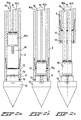
- a head 10 At the lower end of the hollow tube 3 there is a head 10, which head 10 will be explained below, in particular with reference to Figures 2a, 2b and 2c.
- the head 10 in this Example with a downward facing, possibly asymmetrical, lace is executed, and on its top has a protrusion 11, which in a head receiving sleeve 12th fits in, clamping by clamping means 13, in this case one O-ring is held.
- the head receptacle 12 is on the lower segment of the tube 3, in this example with a Threaded connection, fixed. It is evident that the Cross section of the head 10 is somewhat larger than that of the tube 3 is.
- geothermal heat exchanger 15 comprises a slim, elongated body by a single circulation line 16 for one Heat transport medium, for example water, is formed.
- the circulation line 16 shown is mainly composed of two adjacent pipe sections 16a, 16b assembled at its lower end to a connecting part 16c, in this example, connect with a union nut.
- a connecting part 16c In the connecting part 16c there is a channel which connects the two Line sections 16a, 16b connects together.
- the Line sections 16a, 16b are preferably somewhat flexible Line sections made of plastic, but of course you can these line sections can also be made of metal.
- FIGS. 2a-c show that the geothermal heat exchanger 15 and the head 10 are provided with cooperating coupling means which are executed here in such a way that when lowering the Geothermal heat exchanger 15 in the tube 3 automatically with a clutch the head 10 is realized.
- these include Coupling means one with a thread or another toothing provided projection 18 at the lower end of the geothermal heat exchanger 15, and further one or more arranged on the head 10 resilient lips 19 which with the projection 18 of the lowering Geothermal heat exchanger 15 come into play.
- the coupling agents are like this executed that once the clutch has been brought about is, this is maintained when you try to Pull up the geothermal heat exchanger.
- the coupling means would be around the geothermal heat exchanger to connect with the head also the application of glue, Synthetic resin or another adhesive, such as cement, can include.
- the pipe 3 is removed from the ground Help the vehicle 1 pulled up, each time a pipe segment is unscrewed from the pipe. Even if - because of the small Play between the inside of the moving tube 3 and the geothermal heat exchanger 15 - the talk of a significant Friction between the tube 3 and the geothermal heat exchanger 15 is so the geothermal heat exchanger 15 will not move up because of Head 10, so to speak, as anchoring the lower end of the Geothermal heat exchanger 15 is used in the ground. It should be noted that the pipe 3, consciously or unconsciously, have one or more curvatures can, which makes the friction even greater than if the pipe 3 is straight. Sections 16a and 16b of FIG Circulation line 16 be curved in practice and therefore on the Fit inside the tube 3.
- the head 10 protrudes from the tube 3 in this example, whereby is promoted that the head 10 when pulling up the tube 3rd remains. But it is also conceivable that the head is the same, or even a smaller cross section than the pipe and around which To fix your head firmly in the ground, with Anchoring means, for example one or more to the outside moving anchor projections is provided.
- Anchoring means for example one or more to the outside moving anchor projections is provided.
- the head could also like a head which is expandable in cross section in another way be executed.
- the geothermal heat exchanger 15 is only arranged when that Pipe 3 (almost) to the desired depth in the ground driven, can advantageously with a hollow tube 3, composed of pipe segments to be fastened together will be worked. These pipe segments are then as they are pushed into the ground, one after the other attached.
- the geothermal heat exchanger is not a disruptive factor, because this is not yet present in tube 3.
- connection part 16c fits tightly in the tube 3 and gas or Fluid pressure is used to connect the connector - and with it coupled line parts 16a, 16b towards the head 10 float.
- the two line parts 16a, 16b of the circulation line can be on the other Top with an inlet and outlet connection for each Heat transport medium should be provided.
Landscapes
- Engineering & Computer Science (AREA)
- Life Sciences & Earth Sciences (AREA)
- General Life Sciences & Earth Sciences (AREA)
- Chemical & Material Sciences (AREA)
- General Engineering & Computer Science (AREA)
- Mechanical Engineering (AREA)
- Geology (AREA)
- Mining & Mineral Resources (AREA)
- Combustion & Propulsion (AREA)
- Sustainable Development (AREA)
- Sustainable Energy (AREA)
- Fluid Mechanics (AREA)
- Geochemistry & Mineralogy (AREA)
- Physics & Mathematics (AREA)
- Environmental & Geological Engineering (AREA)
- Road Paving Structures (AREA)
- Heat-Exchange Devices With Radiators And Conduit Assemblies (AREA)
Abstract
Description
- Das in das Erdreich Einbringen eines länglichen Hohlrohres, wobei sich an dem unteren Ende des Rohres ein Kopf befindet, welcher Kopf vom Rohr losgekoppelt ist, oder von diesem losgekoppelt werden kann,
- Das Absenken des Erdwärmetauschers in das in das Erdreich eingebrachte Hohlrohr, und das Kuppeln mit dem Kopf des abgesenkten Erdwärmetauschers, und
- Das aus dem Erdreich Hochbringen des Hohlrohres unter Auskopplung des Rohrkopfes, in solcher Weise, daß der Kopf und der mit diesem gekuppelten Erdwärmetauscher in dem Boden zurückbleiben.
- Figur 1
- schematisch das in das Erdreich Einbringen eines erfindungsgemäßen Erdwärmetauschers, und
- Fig. 2a,2b und 2c
- den Bereich in der Nähe des in das Erdreich eingebrachten Kopfes im Querschnitt während drei Stadien des erfindungsgemäßen Verfahrens.
Claims (11)
- Verfahren zum in das Erdreich Einbringen eines Erdwärmetauschers, welcher dazu ausgelegt ist, dem umliegenden Boden Wärme zu entziehen und/oder zuzuuführen, welcher Erdwärmetauscher einen länglichen Körper mit einer oder mehreren Umlaufleitungen für ein Wärmetransportmedium hat, dadurch gekennzeichnet, daß das Verfahren die nachfolgenden Schritte umfaßt:Das in das Erdreich Einbringen eines länglichen Hohlrohres (3), wobei sich an dem unteren Ende des Rohres ein Kopf (10) befindet, welcher Kopf (10) vom Rohr (3) losgekoppelt ist, oder von diesem losgekoppelt werden kann,Das Absenken des Erdwärmetauschers (15) in das in das Erdreich eingebrachte Hohlrohr (3), und das Kuppeln mit dem Kopf (10) des abgesenkten Erdwärmetauschers (15), undDas aus dem Erdreich Hochbringen des Hohlrohres (3) unter Auskopplung des Rohres (3) des Kopfes (10), in solcher Weise, daß der Kopf (10) und der mit diesem gekuppelten Erdwärmetauscher (15) in dem Boden zurückbleiben.
- Verfahren nach Anspruch 1, bei dem Kuppelmittel angewendet werden, die in solcher Weise ausgeführt sind, daß beim Absenken des Erdwärmetauschers automatisch eine Kupplung mit dem Kopf realisiert wird.
- Verfahren nach Anspruch 1 oder 2, bei dem ein Kopf angewendet wird, der solche Abmessungen hat, daß der Kopf (10) aus dem Hohlrohr hinausragt.
- Verfahren nach einem oder mehreren der vorhergehenden Ansprüche, bei dem jede Umlaufleitung (16) zwei Leitungsteile aus Kunststoff umfaßt, die sich zwischen der Oberseite und der Unterseite des Erdwärmetauschers (15) erstrecken, wobei die Leitungsteile (16a, 16b) an der Unterseite über ein Anschlußteil (16c) miteinander verbunden sind.
- Verfahren nach einem oder mehreren der vorhergehenden Ansprüche, bei dem das Hohlrohr (3) in einer Kurvenbahn in das Erdreich gedrückt wird.
- Verfahren nach einem oder mehreren der vorhergehenden Ansprüche, bei dem ein aus miteinander kuppelbaren axialen Rohrsegmenten zusammensetzbares Rohr (3) verwendet wird.
- Verfahren nach einem oder mehreren der vorhergehenden Ansprüche, bei dem ein verfahrbares Fahrzeug (1), auf dem eine Druck- und Zugvorrichtung (2) für das Rohr (3) angeordnet ist, wobei das Fahrzeug mit Mitteln (6) zum Einstellen der Position der Druck- und Zugvorrichtung (2) gegenüber dem Erdreich versehen ist.
- Erdwärmetauschervorrichtung, die dazu ausgelegt ist, in dem Erdreich angeordnet zu werden, um dem umliegenden Boden Wärme zu entziehen und/oder zuzuführen, umfassend einen Erdwärmetauscher mit einem oder mehreren Umlaufleitungen für ein Wärmetransportmedium, welche Umlaufleitungen sich zwischen der Oberseite under der Unterseite des Erdwärmetauschers erstrecken, weiter umfassend einen Kopf, der dazu vorgesehen ist, an der Unterseite des Erdwärmetauschers angeordnet zu werden, dadurch gekennzeichnet, daß der Erdwärmetauscher (15) und der Kopf (10) mit zusammenwirkenden Kuppelmitteln, die eine automatische Kupplung zustande bringen, wenn sich der Erdwärmetauscher dem Kopf nähert, versehen ist.
- Erdwärmetauschervorrichtung nach Anspruch 8, bei der der Kopf zum darauf Angreifen eines Hohlrohres (3) ausgelegt ist, mit welchem eine Kraft auf den Kopf ausgeübt wird, damit der Kopf in das Erdreich eingebracht werden kann.
- Erdwärmetauschervorrichtung nach Anspruch 8 oder 9, bei der der Erdwärmetauscher eine einzige Umlaufleitung (16) hat, die im wesentlichen aus zwei parallelen Leitungsteilen (16a, 16b) besteht.
- Erdwärmetauschervorrichtung nach einem oder mehreren der Ansprüche 8 - 10, bei der der Kopf (10) eine nach unten gerichtete Spitze hat, die in solcher Weise asymmetrisch ausgeführt ist, daß der Kopf sich während des Hineindrückens in das Erdreich in eine vorgegebene Richtung seitwärts zu der Kraft, die von dem Rohr auf den Kopf ausgeübt wird, bewegen möchte.
Applications Claiming Priority (2)
| Application Number | Priority Date | Filing Date | Title |
|---|---|---|---|
| NL1010725 | 1998-12-04 | ||
| NL1010725A NL1010725C1 (nl) | 1998-12-04 | 1998-12-04 | Werkwijze voor het in de bodem aanbrengen van een bodemwarmtewisselaar, alsmede een bodemwarmtewisselaarsamenstel. |
Publications (2)
| Publication Number | Publication Date |
|---|---|
| EP1006322A2 true EP1006322A2 (de) | 2000-06-07 |
| EP1006322A3 EP1006322A3 (de) | 2001-01-31 |
Family
ID=19768251
Family Applications (1)
| Application Number | Title | Priority Date | Filing Date |
|---|---|---|---|
| EP99204063A Withdrawn EP1006322A3 (de) | 1998-12-04 | 1999-12-01 | Verfahren zum Einbringen von einem Erdwärmetauscher in das Erdreich sowie eine Erdwärmetauschervorrichtung |
Country Status (2)
| Country | Link |
|---|---|
| EP (1) | EP1006322A3 (de) |
| NL (1) | NL1010725C1 (de) |
Cited By (14)
| Publication number | Priority date | Publication date | Assignee | Title |
|---|---|---|---|---|
| NL1017654C2 (nl) * | 2001-03-20 | 2002-09-23 | Beton Son Bv | Werkwijze voor het vervaardigen van een betonnen funderingspaal met een inwendig flu´dumkanaal. |
| WO2003060389A1 (de) * | 2002-01-21 | 2003-07-24 | Waterkotte Wärmepumpen Gmbh | Wärmequellen- oder wärmesenken-anlage mit thermischer erdankopplung |
| FR2837868A1 (fr) * | 2002-04-02 | 2003-10-03 | Solterm | Procede d'introduction d'un equipement dans un trou de forage, et dispositif pour sa mise en oeuvre |
| BE1016899A3 (nl) * | 2005-12-20 | 2007-09-04 | Geothermie J Vercruysse | Werkwijze voor het aanbrengen van een bodemwarmtewisselaar in een holte in een bodem en bodemwarmtewisselaar hiervoor bestemd. |
| EP1983274A2 (de) | 2007-04-17 | 2008-10-22 | A & S Umwelttechnologie AG | Erdsonde zur Aufnahme von thermischer Energie aus dem Erdreich und/oder zur Abgabe von thermischer Energie an das Erdreich |
| WO2010028496A1 (en) | 2008-09-12 | 2010-03-18 | Alain Desmeules | System and method for geothermal conduit loop in-ground installation and soil penetrating head therefor |
| EP2206993A1 (de) * | 2009-01-13 | 2010-07-14 | Trevi S.p.A. | Vertikaler Erdwärmetauscher und Installationsverfahren |
| US8256531B1 (en) | 2009-08-06 | 2012-09-04 | Williams Comfort Air, Inc. | Vertizontal geothermal loop and installation method |
| WO2012007756A3 (en) * | 2010-07-16 | 2013-01-24 | Geo-Mole Limited | Two-port percussion mole |
| US8529156B2 (en) | 2009-08-06 | 2013-09-10 | True.Home Heating/Cooling, Inc. | Bit adapter and tube return for vertizontal geothermal loop |
| US9188368B2 (en) | 2009-02-04 | 2015-11-17 | Brooke Erin Desantis | Geothermal flexible conduit loop single pass installation system for dense soils and rock |
| US9291286B2 (en) | 2009-08-06 | 2016-03-22 | WCA Group LLC | Hollow drill rod for slurry application in a geothermal loop |
| WO2017065606A1 (en) | 2015-10-15 | 2017-04-20 | Fodere B.V. | Guided pilot tube |
| EP4198414A1 (de) * | 2021-12-14 | 2023-06-21 | Telapari Oy | Anordnung zur installation von erdwärmerohren |
Families Citing this family (1)
| Publication number | Priority date | Publication date | Assignee | Title |
|---|---|---|---|---|
| NL1037890C2 (nl) * | 2010-04-06 | 2011-10-13 | Demar Heiwerken B V | Werkwijze voor het in een bodem inbrengen van een langwerpig element |
Citations (1)
| Publication number | Priority date | Publication date | Assignee | Title |
|---|---|---|---|---|
| FR2492043A1 (fr) | 1980-10-15 | 1982-04-16 | Svensson Bruno | Installation pour inserer en continu un tube flexible dans le sol d'une maniere sensiblement verticale |
Family Cites Families (4)
| Publication number | Priority date | Publication date | Assignee | Title |
|---|---|---|---|---|
| FR2357721A1 (fr) * | 1976-07-09 | 1978-02-03 | Vignal Maurice | Procede de preparation d'un trou fore dans le sol pour constituer un echangeur geothermique pour les installations de chauffage |
| EP0017783B1 (de) * | 1979-03-23 | 1983-05-25 | Aeroaqua Ag. | Vorrichtung zur Nutzung der Erdwärme und Verfahren zur Herstellung dieser Vorrichtung |
| DE2930773A1 (de) * | 1979-07-28 | 1981-02-12 | Heinz Dipl Ing Borsdorf | Rammnadeln mit verlorener kontaktspitze |
| US4286651A (en) * | 1980-04-28 | 1981-09-01 | Environmental Impact Research Group | Geothermal heating system and method of installing the same |
-
1998
- 1998-12-04 NL NL1010725A patent/NL1010725C1/nl not_active IP Right Cessation
-
1999
- 1999-12-01 EP EP99204063A patent/EP1006322A3/de not_active Withdrawn
Patent Citations (1)
| Publication number | Priority date | Publication date | Assignee | Title |
|---|---|---|---|---|
| FR2492043A1 (fr) | 1980-10-15 | 1982-04-16 | Svensson Bruno | Installation pour inserer en continu un tube flexible dans le sol d'une maniere sensiblement verticale |
Cited By (22)
| Publication number | Priority date | Publication date | Assignee | Title |
|---|---|---|---|---|
| NL1017654C2 (nl) * | 2001-03-20 | 2002-09-23 | Beton Son Bv | Werkwijze voor het vervaardigen van een betonnen funderingspaal met een inwendig flu´dumkanaal. |
| EP1243700A1 (de) * | 2001-03-20 | 2002-09-25 | Beton Son B.V. | Verfahren zur Herstellung eines Stahlbetongründungspfahles mit einem internen Flüssigkeitskanal |
| WO2003060389A1 (de) * | 2002-01-21 | 2003-07-24 | Waterkotte Wärmepumpen Gmbh | Wärmequellen- oder wärmesenken-anlage mit thermischer erdankopplung |
| FR2837868A1 (fr) * | 2002-04-02 | 2003-10-03 | Solterm | Procede d'introduction d'un equipement dans un trou de forage, et dispositif pour sa mise en oeuvre |
| BE1016899A3 (nl) * | 2005-12-20 | 2007-09-04 | Geothermie J Vercruysse | Werkwijze voor het aanbrengen van een bodemwarmtewisselaar in een holte in een bodem en bodemwarmtewisselaar hiervoor bestemd. |
| EP1983274A2 (de) | 2007-04-17 | 2008-10-22 | A & S Umwelttechnologie AG | Erdsonde zur Aufnahme von thermischer Energie aus dem Erdreich und/oder zur Abgabe von thermischer Energie an das Erdreich |
| AT505457B1 (de) * | 2007-04-17 | 2009-04-15 | A & S Umwelttechnologie Ag | Erdsonde zur aufnahme von thermischer energie aus dem erdreich und/oder zur abgabe von thermischer energie an das erdreich |
| EP2334993A4 (de) * | 2008-09-12 | 2014-02-19 | Desantis Brooke Erin | System und verfahren zur bodeninstallation eines geothermischen leitungskreises und bodendurchdringungskopf dafür |
| US20100139886A1 (en) * | 2008-09-12 | 2010-06-10 | Alain Desmeules | System and method for geothermal conduit loop in-ground installation and soil penetrating head therefor |
| WO2010028496A1 (en) | 2008-09-12 | 2010-03-18 | Alain Desmeules | System and method for geothermal conduit loop in-ground installation and soil penetrating head therefor |
| EP2206993A1 (de) * | 2009-01-13 | 2010-07-14 | Trevi S.p.A. | Vertikaler Erdwärmetauscher und Installationsverfahren |
| ITTO20090016A1 (it) * | 2009-01-13 | 2010-07-14 | Trevi Spa | Scambiatore di calore geotermico verticale e procedimento per la sua installazione |
| US9188368B2 (en) | 2009-02-04 | 2015-11-17 | Brooke Erin Desantis | Geothermal flexible conduit loop single pass installation system for dense soils and rock |
| US8529156B2 (en) | 2009-08-06 | 2013-09-10 | True.Home Heating/Cooling, Inc. | Bit adapter and tube return for vertizontal geothermal loop |
| US8312938B2 (en) | 2009-08-06 | 2012-11-20 | Williams Comfort Air, Inc. | Vertizontal geothermal loop and installation method |
| US8256531B1 (en) | 2009-08-06 | 2012-09-04 | Williams Comfort Air, Inc. | Vertizontal geothermal loop and installation method |
| US9291286B2 (en) | 2009-08-06 | 2016-03-22 | WCA Group LLC | Hollow drill rod for slurry application in a geothermal loop |
| WO2012007756A3 (en) * | 2010-07-16 | 2013-01-24 | Geo-Mole Limited | Two-port percussion mole |
| US9217292B2 (en) | 2010-07-16 | 2015-12-22 | Geo-Mole Limited | Two-port percussion mole |
| WO2017065606A1 (en) | 2015-10-15 | 2017-04-20 | Fodere B.V. | Guided pilot tube |
| NL2015621B1 (en) * | 2015-10-15 | 2017-05-09 | Fodere B V | Easy guided pilot tube. |
| EP4198414A1 (de) * | 2021-12-14 | 2023-06-21 | Telapari Oy | Anordnung zur installation von erdwärmerohren |
Also Published As
| Publication number | Publication date |
|---|---|
| NL1010725C1 (nl) | 2000-06-06 |
| EP1006322A3 (de) | 2001-01-31 |
Similar Documents
| Publication | Publication Date | Title |
|---|---|---|
| EP1006322A2 (de) | Verfahren zum Einbringen von einem Erdwärmetauscher in das Erdreich sowie eine Erdwärmetauschervorrichtung | |
| EP2233664B1 (de) | Vorrichtung zum Verbund von Fertigbetonteilen | |
| DE2050754C3 (de) | Kupplungsstück für Rohre | |
| DE4205574C2 (de) | Kanalkörper und Verfahren zum Verlegen eines Kabels in diesem | |
| WO2008019804A1 (de) | Entwässerungsvorrichtung | |
| DE2805495A1 (de) | Kupplung fuer rohre mit einem hauptteil und einer klemmhuelse | |
| DE2841919A1 (de) | Verankerungsvorrichtung | |
| DE3917392A1 (de) | An einem mit gewinde versehenen stehbolzen anbringbare, einteilige leitungshalteklemme | |
| WO2004079252A1 (de) | Rohrführungsadapter | |
| DE60124135T2 (de) | Vorrichtung und verfahren zum einführen und entfernen eines flexiblen ersten materials in ein zweites material | |
| DE10019003B4 (de) | Leicht lösbarer Spindel-Muffen-Verschluss für eine Einbaugarnitur | |
| DE3426246A1 (de) | Verfahren und vorrichtung zum anschliessen seitlicher stutzen oder querleitungen an ein hauptleitungsrohr | |
| CH637791A5 (de) | Vorrichtung zum hinabfuehren eines erdleiters in das erdreich. | |
| DE2755565A1 (de) | Prellbock fuer schienenfahrzeuge | |
| DE2758662A1 (de) | Verankerungsverfahren und verankerungsvorrichtung | |
| DE19953817C2 (de) | Wagenheber mit einem Einsteckdorn | |
| EP1061273A2 (de) | Steckdübelsystem | |
| DE19926060C2 (de) | Steckdübelsystem | |
| DE10060271C1 (de) | Steckdübelsystem | |
| DE10130707A1 (de) | Vorrichtung zum Durchführen von Kabeln, Leitungen und dergleichen durch eine Gebäudewand | |
| DE1954247A1 (de) | Schubsicherung der Steckmuffenverbindung bei Druckrohren bzw. Formstuecken | |
| AT504914B1 (de) | Rohrverbindungsmuffe | |
| DE29520861U1 (de) | Erdanker | |
| DE4127311A1 (de) | Rohrvorpresseinrichtung und verfahren zur errichtung von wassergewinnungsanlagen | |
| DE19818990A1 (de) | Befestigungselement nach dem Dübelprinzip für in Kanälen oder Rohren zu verlegende Kabel |
Legal Events
| Date | Code | Title | Description |
|---|---|---|---|
| PUAI | Public reference made under article 153(3) epc to a published international application that has entered the european phase |
Free format text: ORIGINAL CODE: 0009012 |
|
| AK | Designated contracting states |
Kind code of ref document: A2 Designated state(s): AT BE CH CY DE DK ES FI FR GB GR IE IT LI LU MC NL PT SE |
|
| AX | Request for extension of the european patent |
Free format text: AL;LT;LV;MK;RO;SI |
|
| PUAL | Search report despatched |
Free format text: ORIGINAL CODE: 0009013 |
|
| AK | Designated contracting states |
Kind code of ref document: A3 Designated state(s): AT BE CH CY DE DK ES FI FR GB GR IE IT LI LU MC NL PT SE |
|
| AX | Request for extension of the european patent |
Free format text: AL;LT;LV;MK;RO;SI |
|
| 17P | Request for examination filed |
Effective date: 20010720 |
|
| AKX | Designation fees paid |
Free format text: AT BE CH CY DE DK ES FI FR GB GR IE IT LI LU MC NL PT SE |
|
| AXX | Extension fees paid |
Free format text: LT PAYMENT 20010720;LV PAYMENT 20010720;RO PAYMENT 20010720 |
|
| 17Q | First examination report despatched |
Effective date: 20031009 |
|
| STAA | Information on the status of an ep patent application or granted ep patent |
Free format text: STATUS: THE APPLICATION IS DEEMED TO BE WITHDRAWN |
|
| 18D | Application deemed to be withdrawn |
Effective date: 20040420 |