EP1006343A1 - Spannvorrichtung für ein Instrument zur Messung einer Eigenschaft einer Flüssigkeit - Google Patents
Spannvorrichtung für ein Instrument zur Messung einer Eigenschaft einer Flüssigkeit Download PDFInfo
- Publication number
- EP1006343A1 EP1006343A1 EP99490040A EP99490040A EP1006343A1 EP 1006343 A1 EP1006343 A1 EP 1006343A1 EP 99490040 A EP99490040 A EP 99490040A EP 99490040 A EP99490040 A EP 99490040A EP 1006343 A1 EP1006343 A1 EP 1006343A1
- Authority
- EP
- European Patent Office
- Prior art keywords
- hand
- fluid
- piston
- pipe
- stops
- Prior art date
- Legal status (The legal status is an assumption and is not a legal conclusion. Google has not performed a legal analysis and makes no representation as to the accuracy of the status listed.)
- Granted
Links
- 239000012530 fluid Substances 0.000 title claims abstract description 35
- 238000006073 displacement reaction Methods 0.000 claims description 8
- 238000007789 sealing Methods 0.000 claims description 7
- 238000011144 upstream manufacturing Methods 0.000 claims description 6
- 230000000295 complement effect Effects 0.000 claims description 4
- 238000013519 translation Methods 0.000 claims description 4
- 230000000694 effects Effects 0.000 claims description 3
- XLYOFNOQVPJJNP-UHFFFAOYSA-N water Substances O XLYOFNOQVPJJNP-UHFFFAOYSA-N 0.000 description 5
- 238000005259 measurement Methods 0.000 description 3
- 208000031968 Cadaver Diseases 0.000 description 2
- 102000000591 Tight Junction Proteins Human genes 0.000 description 2
- 108010002321 Tight Junction Proteins Proteins 0.000 description 2
- 238000009434 installation Methods 0.000 description 2
- 210000001578 tight junction Anatomy 0.000 description 2
- 238000004891 communication Methods 0.000 description 1
- 238000013461 design Methods 0.000 description 1
- 230000003100 immobilizing effect Effects 0.000 description 1
- 238000012423 maintenance Methods 0.000 description 1
- 229920002994 synthetic fiber Polymers 0.000 description 1
Images

Classifications
-
- F—MECHANICAL ENGINEERING; LIGHTING; HEATING; WEAPONS; BLASTING
- F16—ENGINEERING ELEMENTS AND UNITS; GENERAL MEASURES FOR PRODUCING AND MAINTAINING EFFECTIVE FUNCTIONING OF MACHINES OR INSTALLATIONS; THERMAL INSULATION IN GENERAL
- F16L—PIPES; JOINTS OR FITTINGS FOR PIPES; SUPPORTS FOR PIPES, CABLES OR PROTECTIVE TUBING; MEANS FOR THERMAL INSULATION IN GENERAL
- F16L25/00—Construction or details of pipe joints not provided for in, or of interest apart from, groups F16L13/00 - F16L23/00
- F16L25/12—Joints for pipes being spaced apart axially
-
- G—PHYSICS
- G01—MEASURING; TESTING
- G01F—MEASURING VOLUME, VOLUME FLOW, MASS FLOW OR LIQUID LEVEL; METERING BY VOLUME
- G01F15/00—Details of, or accessories for, apparatus of groups G01F1/00 - G01F13/00 insofar as such details or appliances are not adapted to particular types of such apparatus
- G01F15/18—Supports or connecting means for meters
- G01F15/185—Connecting means, e.g. bypass conduits
Definitions
- the invention relates to a device for holding between two sections of a pipe, of a device, in particular, of measurement in particular of a characteristic of a fluid circulating under pressure in this pipe.
- the invention applies advantageously, but not exclusively to a device for holding a water meter, volumetric or speed, between two sections of a supply line to an installation.
- a water meter includes a body which, housing a measure, is intended to be at least partially crossed by water.
- the meter body comprises two tubular parts which, aligned, constitute, one, an inlet duct and, the other, an outlet duct some water.
- tubular parts are conventionally each equipped, on the one hand, an extreme bearing surface sealed on a complementary bearing, such as a span presented by a section of pipe and, on the other hand, an external thread intended to cooperate with a connection nut to a tubular section, such as a nut for connection to the aforementioned pipe section.
- a complementary bearing such as a span presented by a section of pipe
- an external thread intended to cooperate with a connection nut to a tubular section, such as a nut for connection to the aforementioned pipe section.
- meters are very often installed in places where is particularly difficult to manipulate keys.
- one of the tubular sections of the support is movable and a cam allows the doors to be pressed against each other extremes.
- a result which the invention aims to obtain is a device which, while being economical to make, allows to quickly assemble and disassemble a measurement, like a meter without special skill and without using keys maneuver.
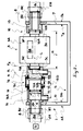
- That 2A of the pipe sections 2A, 2B which conveys the fluid under pressure 4 from source S is said upstream pipe section 2A or inlet of the fluid, while the other section 2B is said downstream or outlet section of the fluid.
- the apparatus 3 comprises a body 3A which, in particular housing an instrument 3B of measurement, is intended to be at least partially traversed by the fluid under pressure 4 flowing in the pipe.
- the body 3A of the device 3 comprises two tubular parts 3C, 3D which, aligned along an axis L, constitute, one 3C, a fluid intake duct under pressure 4 and, the other 3D, an outlet pipe for said fluid under pressure 4.
- tubular parts 3C, 3D are each equipped with an extreme range 3E, 3F waterproof support on a complementary surface 9A, 10A, at least indirectly connected to a section 2A, 2B of pipe.
- the extreme ranges 3E, 3F of the body 3A of the device are located in substantially parallel planes spaced by a determined value E.
- the holding device 1 comprises a rigid structure 5 which, in particular intended to be fixed to a support (not shown), has two walls 6, 7 substantially parallel with two opposite faces 6A, 7A and two faces in opposite 6B, 7B.
- structure 5 has been strongly schematized.
- the two opposite faces 6A, 7A each carry a means 8 of tight connection and fixing at one end of a section 2A, 2B of conduct.
- the two faces 6B, 7B facing each other are each equipped with a means 9, 10 of tight junction and fixing of one of the 3C inlet and 3D outlet ducts of fluid 4 which are carried by the body 3A of the device 3, these means 9, 10 of junction making it possible to establish communication with the so-called 8 means of tight connection to sections 2A, 2B of pipe.
- the means 9, 10 of tight junction each include two ranges 9A, 9B and 10A, 10B of which, one 9B, 10B for centering one of the conduits 3C, 3D of the device 3 and the other 9A, 10A waterproof support on the extreme range 3E, 3F presented by this conduit 3C, 3D.
- the ranges 9A, 10A are, for example, equipped with a seal (not represented).
- At least one 9A, 10A of the sealing bearing surfaces against a bearing extreme of the body is associated with a means 11 of controlled displacement and guidance between two positions P1, P2 including a position P1 spaced from the plane of the extreme range considered and a position P2 of effective support against this range extreme.
- the range 10A opposite the mobile range 9A is formed in a tubular part 15 of revolution linked to the structure 5.
- the device of the invention it is easy to set up or remove a device 3, without tools.
- the means 11 for controlled displacement and guidance equips the upstream part of the holding device 1, that is to say the part of the device which is connected to the source S of pressurized fluid.
- the piston 12 is biased by an elastic member 13, in the direction of application of the mobile range 9A against the extreme range 3E 3.
- the piston 12, on the one hand, is guided in translation in a chamber 12B reserved in a room 14 integral with the structure 5 and, on the other hand, is consisting of a part which has, on the one hand, an axial channel 12C allowing the passage of the fluid 4 towards the device 3 and, on the other hand, organized around this channel 12C, an annular face 12A subjected to the action of the fluid under pressure.
- the part 14 which, integral with the structure 5, guides the piston 12, is, by example, a tubular part of revolution.
- the piston 12, on the one hand is guided in translation in a room 12B reserved in a room integral with the structure 5 and, on the other hand, consists of a cylindrical part which has, on the one hand, a circular face 12A exposed to the action of the fluid and, on the other hand, a channel 12C which, for the passage of the fluid towards the device is, by a pipe bypass 12D, at least indirectly connected to the upstream pipe section 2A.
- the connecting element consists of a threaded seat intended to cooperate with a captive nut carried by the pipe section 2A, 2B.
- the device of the invention is made at least partially of synthetic material.
- the displacement means 11 controlled and guiding comprises means 16 for sealing the device 3 in position mounted on the device, i.e. a means therefore the function is to reveal an unauthorized disassembly of the device 3.
- the rigid connection element 16C is an element whose structure must be broken to release the stops 16A, 16B.
Landscapes
- Engineering & Computer Science (AREA)
- General Engineering & Computer Science (AREA)
- Mechanical Engineering (AREA)
- Physics & Mathematics (AREA)
- Fluid Mechanics (AREA)
- General Physics & Mathematics (AREA)
- Sampling And Sample Adjustment (AREA)
- Measuring Fluid Pressure (AREA)
- Measurement Of Radiation (AREA)
- Investigating Or Analyzing Materials By The Use Of Electric Means (AREA)
Applications Claiming Priority (2)
| Application Number | Priority Date | Filing Date | Title |
|---|---|---|---|
| FR9815451A FR2786863B1 (fr) | 1998-12-03 | 1998-12-03 | Dispositif de maintien entre deux troncons d'une conduite, d'un appareil de mesure d'une caracteristique d'un fluide |
| FR9815451 | 1998-12-03 |
Publications (2)
| Publication Number | Publication Date |
|---|---|
| EP1006343A1 true EP1006343A1 (de) | 2000-06-07 |
| EP1006343B1 EP1006343B1 (de) | 2010-09-01 |
Family
ID=9533694
Family Applications (1)
| Application Number | Title | Priority Date | Filing Date |
|---|---|---|---|
| EP99490040A Expired - Lifetime EP1006343B1 (de) | 1998-12-03 | 1999-12-01 | Spannvorrichtung für ein Instrument zur Messung einer Eigenschaft einer Flüssigkeit |
Country Status (4)
| Country | Link |
|---|---|
| EP (1) | EP1006343B1 (de) |
| AT (1) | ATE479883T1 (de) |
| DE (1) | DE69942718D1 (de) |
| FR (1) | FR2786863B1 (de) |
Cited By (5)
| Publication number | Priority date | Publication date | Assignee | Title |
|---|---|---|---|---|
| ITMI20121488A1 (it) * | 2012-09-06 | 2014-03-07 | Effepi Srl | Sistema per incasso a muro di un miscelatore idraulico e relativo metodo di installazione |
| CN112414499A (zh) * | 2020-09-28 | 2021-02-26 | 成都易信达科技股份有限公司 | 一种NB-ioT物联网智能水表 |
| WO2021177967A1 (en) * | 2020-03-05 | 2021-09-10 | Micro Motion, Inc. | Flow meter coupling system |
| FR3114332A1 (fr) * | 2020-09-22 | 2022-03-25 | Etablissements Saint Germain Et Straub | Dispositif de maintien |
| CN120927235A (zh) * | 2025-10-11 | 2025-11-11 | 西安亚龙航空机电股份有限公司 | 一种适用于腔道内流体测量的测量耙 |
Citations (3)
| Publication number | Priority date | Publication date | Assignee | Title |
|---|---|---|---|---|
| US4516794A (en) * | 1982-11-05 | 1985-05-14 | Zorwick Corp. | Meter pit mounted holder for a water flow control device |
| US5052721A (en) * | 1989-03-31 | 1991-10-01 | Gorman Jr Philip P | Water meter service coupling |
| FR2743629A3 (fr) * | 1996-01-16 | 1997-07-18 | Auxiliares De Instalaciones Sa | Nouvel agencement pour le montage et le demontage rapides de compteurs d'eau et appareils analogues |
-
1998
- 1998-12-03 FR FR9815451A patent/FR2786863B1/fr not_active Expired - Fee Related
-
1999
- 1999-12-01 AT AT99490040T patent/ATE479883T1/de not_active IP Right Cessation
- 1999-12-01 DE DE69942718T patent/DE69942718D1/de not_active Expired - Lifetime
- 1999-12-01 EP EP99490040A patent/EP1006343B1/de not_active Expired - Lifetime
Patent Citations (3)
| Publication number | Priority date | Publication date | Assignee | Title |
|---|---|---|---|---|
| US4516794A (en) * | 1982-11-05 | 1985-05-14 | Zorwick Corp. | Meter pit mounted holder for a water flow control device |
| US5052721A (en) * | 1989-03-31 | 1991-10-01 | Gorman Jr Philip P | Water meter service coupling |
| FR2743629A3 (fr) * | 1996-01-16 | 1997-07-18 | Auxiliares De Instalaciones Sa | Nouvel agencement pour le montage et le demontage rapides de compteurs d'eau et appareils analogues |
Cited By (11)
| Publication number | Priority date | Publication date | Assignee | Title |
|---|---|---|---|---|
| ITMI20121488A1 (it) * | 2012-09-06 | 2014-03-07 | Effepi Srl | Sistema per incasso a muro di un miscelatore idraulico e relativo metodo di installazione |
| WO2021177967A1 (en) * | 2020-03-05 | 2021-09-10 | Micro Motion, Inc. | Flow meter coupling system |
| CN115244366A (zh) * | 2020-03-05 | 2022-10-25 | 高准有限公司 | 流量计联接系统 |
| JP2023517874A (ja) * | 2020-03-05 | 2023-04-27 | マイクロ モーション インコーポレイテッド | 流量計連結システム |
| JP7480330B2 (ja) | 2020-03-05 | 2024-05-09 | マイクロ モーション インコーポレイテッド | 流量計連結システム |
| US12196594B2 (en) | 2020-03-05 | 2025-01-14 | Micro Motion, Inc. | Flow meter coupling system for reduced axial stress |
| CN115244366B (zh) * | 2020-03-05 | 2026-02-27 | 高准有限公司 | 流量计联接系统 |
| FR3114332A1 (fr) * | 2020-09-22 | 2022-03-25 | Etablissements Saint Germain Et Straub | Dispositif de maintien |
| WO2022064120A1 (fr) * | 2020-09-22 | 2022-03-31 | Etablissements Saint Germain Et Straub | Dispositif de maintien |
| CN112414499A (zh) * | 2020-09-28 | 2021-02-26 | 成都易信达科技股份有限公司 | 一种NB-ioT物联网智能水表 |
| CN120927235A (zh) * | 2025-10-11 | 2025-11-11 | 西安亚龙航空机电股份有限公司 | 一种适用于腔道内流体测量的测量耙 |
Also Published As
| Publication number | Publication date |
|---|---|
| EP1006343B1 (de) | 2010-09-01 |
| FR2786863B1 (fr) | 2001-02-02 |
| FR2786863A1 (fr) | 2000-06-09 |
| DE69942718D1 (de) | 2010-10-14 |
| ATE479883T1 (de) | 2010-09-15 |
Similar Documents
| Publication | Publication Date | Title |
|---|---|---|
| EP0328472B1 (de) | Anlasser-Verbindungsstück für die stufenlose Druckzufuhr in pneumatischen Anlagen | |
| EP1006343B1 (de) | Spannvorrichtung für ein Instrument zur Messung einer Eigenschaft einer Flüssigkeit | |
| EP1055080B1 (de) | Vorrichtung und verfahren zum montieren eines sattels auf einer druckrohrleitung und dafür geeignetes ventil | |
| WO2020225262A1 (fr) | Tête de réservoir pour gaz sous pression | |
| FR2761454A1 (fr) | Robinet a manometre pour bouteille de gaz comprime | |
| FR2748566A1 (fr) | Dispositif de prise d'echantillon sur une canalisation | |
| FR3041686A1 (fr) | Dispositif de support d'une canalisation dans une turbomachine | |
| FR2660046A1 (fr) | Compensateur de dilatation pour les canalisations. | |
| FR3054634A1 (fr) | Clapet a bille avec robinet de purge incorpore | |
| WO2023187212A1 (fr) | Tête de connexion rapportable sur une ouverture d'un élément de tuyauterie à bride pour son contrôle sous pression | |
| EP0446547B1 (de) | Pneumatische Messeinrichtung | |
| FR2704293A1 (fr) | Robinet à tournant cylindrique. | |
| FR2510228A1 (fr) | Systeme de connexion de raccords automatiques pour tuyaux a des dispositifs de distribution de fluides liquides ou gazeux | |
| CH610211A5 (en) | Cock for pipe conveying fluid at pressure | |
| EP0926424A1 (de) | Verteiler- und Herstellungsverfahren , sowie Verbindungsanordnung mit solchem Verteiler | |
| EP3346169B1 (de) | Fluid-zuleitungsanschluss für sanitärarmatur mit rückschlagventil | |
| FR2631675A1 (fr) | Vanne a soufflet | |
| EP3775645B1 (de) | Verbessertes regelventil mit integrierter spülfunktion | |
| EP1298257B1 (de) | Verbindungselement für Sanitärinstallationen | |
| BE568730A (de) | ||
| FR2694972A1 (fr) | Dispositif de contrôle de l'écoulement d'un fluide. | |
| FR2505966A1 (fr) | Vanne a plusieurs voies | |
| FR2894013A1 (fr) | Repartiteur hydraulique de raccordement de deux generateurs de chaleur | |
| EP0499498A1 (de) | Manuell und pneumatisch betätigbare Absperrarmatur | |
| FR2871542A3 (fr) | Soupage spherique |
Legal Events
| Date | Code | Title | Description |
|---|---|---|---|
| PUAI | Public reference made under article 153(3) epc to a published international application that has entered the european phase |
Free format text: ORIGINAL CODE: 0009012 |
|
| AK | Designated contracting states |
Kind code of ref document: A1 Designated state(s): AT BE CH CY DE DK ES FI FR GB GR IE IT LI LU MC NL PT SE |
|
| AX | Request for extension of the european patent |
Free format text: AL;LT;LV;MK;RO;SI |
|
| 17P | Request for examination filed |
Effective date: 20000731 |
|
| AKX | Designation fees paid |
Free format text: AT BE CH CY DE DK ES FI FR GB GR IE IT LI LU MC NL PT SE |
|
| 17Q | First examination report despatched |
Effective date: 20060929 |
|
| 17Q | First examination report despatched |
Effective date: 20060929 |
|
| GRAP | Despatch of communication of intention to grant a patent |
Free format text: ORIGINAL CODE: EPIDOSNIGR1 |
|
| GRAS | Grant fee paid |
Free format text: ORIGINAL CODE: EPIDOSNIGR3 |
|
| GRAA | (expected) grant |
Free format text: ORIGINAL CODE: 0009210 |
|
| RAP1 | Party data changed (applicant data changed or rights of an application transferred) |
Owner name: HYDROMECA |
|
| AK | Designated contracting states |
Kind code of ref document: B1 Designated state(s): AT BE CH CY DE DK ES FI FR GB GR IE IT LI LU MC NL PT SE |
|
| REG | Reference to a national code |
Ref country code: GB Ref legal event code: FG4D Free format text: NOT ENGLISH |
|
| REG | Reference to a national code |
Ref country code: CH Ref legal event code: EP |
|
| REG | Reference to a national code |
Ref country code: IE Ref legal event code: FG4D Free format text: LANGUAGE OF EP DOCUMENT: FRENCH |
|
| REF | Corresponds to: |
Ref document number: 69942718 Country of ref document: DE Date of ref document: 20101014 Kind code of ref document: P |
|
| REG | Reference to a national code |
Ref country code: NL Ref legal event code: VDEP Effective date: 20100901 |
|
| PG25 | Lapsed in a contracting state [announced via postgrant information from national office to epo] |
Ref country code: FI Free format text: LAPSE BECAUSE OF FAILURE TO SUBMIT A TRANSLATION OF THE DESCRIPTION OR TO PAY THE FEE WITHIN THE PRESCRIBED TIME-LIMIT Effective date: 20100901 Ref country code: AT Free format text: LAPSE BECAUSE OF FAILURE TO SUBMIT A TRANSLATION OF THE DESCRIPTION OR TO PAY THE FEE WITHIN THE PRESCRIBED TIME-LIMIT Effective date: 20100901 |
|
| PG25 | Lapsed in a contracting state [announced via postgrant information from national office to epo] |
Ref country code: CY Free format text: LAPSE BECAUSE OF FAILURE TO SUBMIT A TRANSLATION OF THE DESCRIPTION OR TO PAY THE FEE WITHIN THE PRESCRIBED TIME-LIMIT Effective date: 20100901 |
|
| REG | Reference to a national code |
Ref country code: IE Ref legal event code: FD4D |
|
| PG25 | Lapsed in a contracting state [announced via postgrant information from national office to epo] |
Ref country code: GR Free format text: LAPSE BECAUSE OF FAILURE TO SUBMIT A TRANSLATION OF THE DESCRIPTION OR TO PAY THE FEE WITHIN THE PRESCRIBED TIME-LIMIT Effective date: 20101202 Ref country code: NL Free format text: LAPSE BECAUSE OF FAILURE TO SUBMIT A TRANSLATION OF THE DESCRIPTION OR TO PAY THE FEE WITHIN THE PRESCRIBED TIME-LIMIT Effective date: 20100901 Ref country code: SE Free format text: LAPSE BECAUSE OF FAILURE TO SUBMIT A TRANSLATION OF THE DESCRIPTION OR TO PAY THE FEE WITHIN THE PRESCRIBED TIME-LIMIT Effective date: 20100901 |
|
| PG25 | Lapsed in a contracting state [announced via postgrant information from national office to epo] |
Ref country code: IE Free format text: LAPSE BECAUSE OF FAILURE TO SUBMIT A TRANSLATION OF THE DESCRIPTION OR TO PAY THE FEE WITHIN THE PRESCRIBED TIME-LIMIT Effective date: 20100901 |
|
| PG25 | Lapsed in a contracting state [announced via postgrant information from national office to epo] |
Ref country code: PT Free format text: LAPSE BECAUSE OF FAILURE TO SUBMIT A TRANSLATION OF THE DESCRIPTION OR TO PAY THE FEE WITHIN THE PRESCRIBED TIME-LIMIT Effective date: 20110103 Ref country code: IT Free format text: LAPSE BECAUSE OF FAILURE TO SUBMIT A TRANSLATION OF THE DESCRIPTION OR TO PAY THE FEE WITHIN THE PRESCRIBED TIME-LIMIT Effective date: 20100901 |
|
| PG25 | Lapsed in a contracting state [announced via postgrant information from national office to epo] |
Ref country code: ES Free format text: LAPSE BECAUSE OF FAILURE TO SUBMIT A TRANSLATION OF THE DESCRIPTION OR TO PAY THE FEE WITHIN THE PRESCRIBED TIME-LIMIT Effective date: 20101212 |
|
| PLBE | No opposition filed within time limit |
Free format text: ORIGINAL CODE: 0009261 |
|
| STAA | Information on the status of an ep patent application or granted ep patent |
Free format text: STATUS: NO OPPOSITION FILED WITHIN TIME LIMIT |
|
| PG25 | Lapsed in a contracting state [announced via postgrant information from national office to epo] |
Ref country code: MC Free format text: LAPSE BECAUSE OF NON-PAYMENT OF DUE FEES Effective date: 20101231 |
|
| REG | Reference to a national code |
Ref country code: CH Ref legal event code: PL |
|
| 26N | No opposition filed |
Effective date: 20110606 |
|
| PG25 | Lapsed in a contracting state [announced via postgrant information from national office to epo] |
Ref country code: DK Free format text: LAPSE BECAUSE OF FAILURE TO SUBMIT A TRANSLATION OF THE DESCRIPTION OR TO PAY THE FEE WITHIN THE PRESCRIBED TIME-LIMIT Effective date: 20100901 |
|
| REG | Reference to a national code |
Ref country code: DE Ref legal event code: R097 Ref document number: 69942718 Country of ref document: DE Effective date: 20110606 |
|
| PG25 | Lapsed in a contracting state [announced via postgrant information from national office to epo] |
Ref country code: CH Free format text: LAPSE BECAUSE OF NON-PAYMENT OF DUE FEES Effective date: 20101231 Ref country code: LI Free format text: LAPSE BECAUSE OF NON-PAYMENT OF DUE FEES Effective date: 20101231 |
|
| REG | Reference to a national code |
Ref country code: DE Ref legal event code: R119 Ref document number: 69942718 Country of ref document: DE Effective date: 20110701 |
|
| PG25 | Lapsed in a contracting state [announced via postgrant information from national office to epo] |
Ref country code: DE Free format text: LAPSE BECAUSE OF NON-PAYMENT OF DUE FEES Effective date: 20110701 |
|
| PG25 | Lapsed in a contracting state [announced via postgrant information from national office to epo] |
Ref country code: LU Free format text: LAPSE BECAUSE OF NON-PAYMENT OF DUE FEES Effective date: 20101201 |
|
| REG | Reference to a national code |
Ref country code: FR Ref legal event code: PLFP Year of fee payment: 17 |
|
| REG | Reference to a national code |
Ref country code: FR Ref legal event code: PLFP Year of fee payment: 18 |
|
| REG | Reference to a national code |
Ref country code: FR Ref legal event code: PLFP Year of fee payment: 19 |
|
| PGFP | Annual fee paid to national office [announced via postgrant information from national office to epo] |
Ref country code: FR Payment date: 20181221 Year of fee payment: 20 Ref country code: BE Payment date: 20181227 Year of fee payment: 20 Ref country code: GB Payment date: 20181227 Year of fee payment: 20 |
|
| REG | Reference to a national code |
Ref country code: BE Ref legal event code: MK Effective date: 20191201 |
|
| REG | Reference to a national code |
Ref country code: GB Ref legal event code: PE20 Expiry date: 20191130 |
|
| PG25 | Lapsed in a contracting state [announced via postgrant information from national office to epo] |
Ref country code: GB Free format text: LAPSE BECAUSE OF EXPIRATION OF PROTECTION Effective date: 20191130 |