EP1006482A2 - Codage séparé d' objets dans une image et de leurs limites - Google Patents
Codage séparé d' objets dans une image et de leurs limites Download PDFInfo
- Publication number
- EP1006482A2 EP1006482A2 EP99309591A EP99309591A EP1006482A2 EP 1006482 A2 EP1006482 A2 EP 1006482A2 EP 99309591 A EP99309591 A EP 99309591A EP 99309591 A EP99309591 A EP 99309591A EP 1006482 A2 EP1006482 A2 EP 1006482A2
- Authority
- EP
- European Patent Office
- Prior art keywords
- data
- texture
- image
- shape
- boundary portion
- Prior art date
- Legal status (The legal status is an assumption and is not a legal conclusion. Google has not performed a legal analysis and makes no representation as to the accuracy of the status listed.)
- Withdrawn
Links
Images












Classifications
-
- G—PHYSICS
- G06—COMPUTING OR CALCULATING; COUNTING
- G06T—IMAGE DATA PROCESSING OR GENERATION, IN GENERAL
- G06T9/00—Image coding
- G06T9/20—Contour coding, e.g. using detection of edges
-
- H—ELECTRICITY
- H04—ELECTRIC COMMUNICATION TECHNIQUE
- H04N—PICTORIAL COMMUNICATION, e.g. TELEVISION
- H04N19/00—Methods or arrangements for coding, decoding, compressing or decompressing digital video signals
- H04N19/10—Methods or arrangements for coding, decoding, compressing or decompressing digital video signals using adaptive coding
- H04N19/134—Methods or arrangements for coding, decoding, compressing or decompressing digital video signals using adaptive coding characterised by the element, parameter or criterion affecting or controlling the adaptive coding
- H04N19/136—Incoming video signal characteristics or properties
- H04N19/14—Coding unit complexity, e.g. amount of activity or edge presence estimation
-
- H—ELECTRICITY
- H04—ELECTRIC COMMUNICATION TECHNIQUE
- H04N—PICTORIAL COMMUNICATION, e.g. TELEVISION
- H04N19/00—Methods or arrangements for coding, decoding, compressing or decompressing digital video signals
- H04N19/10—Methods or arrangements for coding, decoding, compressing or decompressing digital video signals using adaptive coding
- H04N19/169—Methods or arrangements for coding, decoding, compressing or decompressing digital video signals using adaptive coding characterised by the coding unit, i.e. the structural portion or semantic portion of the video signal being the object or the subject of the adaptive coding
- H04N19/17—Methods or arrangements for coding, decoding, compressing or decompressing digital video signals using adaptive coding characterised by the coding unit, i.e. the structural portion or semantic portion of the video signal being the object or the subject of the adaptive coding the unit being an image region, e.g. an object
- H04N19/176—Methods or arrangements for coding, decoding, compressing or decompressing digital video signals using adaptive coding characterised by the coding unit, i.e. the structural portion or semantic portion of the video signal being the object or the subject of the adaptive coding the unit being an image region, e.g. an object the region being a block, e.g. a macroblock
-
- H—ELECTRICITY
- H04—ELECTRIC COMMUNICATION TECHNIQUE
- H04N—PICTORIAL COMMUNICATION, e.g. TELEVISION
- H04N19/00—Methods or arrangements for coding, decoding, compressing or decompressing digital video signals
- H04N19/10—Methods or arrangements for coding, decoding, compressing or decompressing digital video signals using adaptive coding
- H04N19/169—Methods or arrangements for coding, decoding, compressing or decompressing digital video signals using adaptive coding characterised by the coding unit, i.e. the structural portion or semantic portion of the video signal being the object or the subject of the adaptive coding
- H04N19/182—Methods or arrangements for coding, decoding, compressing or decompressing digital video signals using adaptive coding characterised by the coding unit, i.e. the structural portion or semantic portion of the video signal being the object or the subject of the adaptive coding the unit being a pixel
-
- H—ELECTRICITY
- H04—ELECTRIC COMMUNICATION TECHNIQUE
- H04N—PICTORIAL COMMUNICATION, e.g. TELEVISION
- H04N19/00—Methods or arrangements for coding, decoding, compressing or decompressing digital video signals
- H04N19/10—Methods or arrangements for coding, decoding, compressing or decompressing digital video signals using adaptive coding
- H04N19/169—Methods or arrangements for coding, decoding, compressing or decompressing digital video signals using adaptive coding characterised by the coding unit, i.e. the structural portion or semantic portion of the video signal being the object or the subject of the adaptive coding
- H04N19/186—Methods or arrangements for coding, decoding, compressing or decompressing digital video signals using adaptive coding characterised by the coding unit, i.e. the structural portion or semantic portion of the video signal being the object or the subject of the adaptive coding the unit being a colour or a chrominance component
-
- H—ELECTRICITY
- H04—ELECTRIC COMMUNICATION TECHNIQUE
- H04N—PICTORIAL COMMUNICATION, e.g. TELEVISION
- H04N19/00—Methods or arrangements for coding, decoding, compressing or decompressing digital video signals
- H04N19/20—Methods or arrangements for coding, decoding, compressing or decompressing digital video signals using video object coding
-
- H—ELECTRICITY
- H04—ELECTRIC COMMUNICATION TECHNIQUE
- H04N—PICTORIAL COMMUNICATION, e.g. TELEVISION
- H04N19/00—Methods or arrangements for coding, decoding, compressing or decompressing digital video signals
- H04N19/60—Methods or arrangements for coding, decoding, compressing or decompressing digital video signals using transform coding
- H04N19/61—Methods or arrangements for coding, decoding, compressing or decompressing digital video signals using transform coding in combination with predictive coding
-
- H—ELECTRICITY
- H04—ELECTRIC COMMUNICATION TECHNIQUE
- H04N—PICTORIAL COMMUNICATION, e.g. TELEVISION
- H04N21/00—Selective content distribution, e.g. interactive television or video on demand [VOD]
- H04N21/20—Servers specifically adapted for the distribution of content, e.g. VOD servers; Operations thereof
- H04N21/23—Processing of content or additional data; Elementary server operations; Server middleware
- H04N21/234—Processing of video elementary streams, e.g. splicing of video streams or manipulating encoded video stream scene graphs
- H04N21/2343—Processing of video elementary streams, e.g. splicing of video streams or manipulating encoded video stream scene graphs involving reformatting operations of video signals for distribution or compliance with end-user requests or end-user device requirements
- H04N21/234318—Processing of video elementary streams, e.g. splicing of video streams or manipulating encoded video stream scene graphs involving reformatting operations of video signals for distribution or compliance with end-user requests or end-user device requirements by decomposing into objects, e.g. MPEG-4 objects
Definitions
- This invention relates to an image processing apparatus and method, and an image processing system and, more particularly, to an image processing apparatus and method, and an image processing system, which extract and synthesize objects in a color image.
- MPEG4 Moving Picture Experts Group Phase 4
- MPEG2 In a conventional moving image coding scheme represented by MPEG2, coding is done in units of frames or fields.
- MPEG4 is characterized by handling video and audio data as objects.
- objects contained in video data are independently encoded, and can be independently handled.
- encoding/decoding is done in units of objects, thus allowing various applications in units of objects, such as improvement of coding efficiency, data distribution depending on transmission paths, re-processing of images, and the like, which cannot be attained by the conventional scheme.
- Objects to be handled by MPEG4 includes shape data indicating a shape and ⁇ data indicating transparency of an object in addition to texture data indicating a pattern itself by luminance (Y) data and color difference (chroma) data.
- Y luminance
- chroma color difference
- moving image data has a format called 4 : 2 : 0 obtained by subsampling chroma data to 1/2 with respect to Y data in both the horizontal and vertical directions in view of visual characteristics and data amount.
- Fig. 27 shows this format, i.e., an example of pixel matrices of Y and chroma data in chroma-subsampled moving image data. As can be seen from Fig. 27, one Cr/Cb chroma pixel is sampled per four Y pixels.
- an object having an arbitrary shape in MPEG4 is extracted as a region 1001 called a "bounding box" that circumscribes an object, as shown in Fig. 28. That is, an object in Fig. 28 is a human figure within the bounding box 1001.
- the bounding box 1001 has a size corresponding to an integer multiple of that of a macroblock 1002, and its absolute position is expressed by the distance from the upper left corner of a frame.
- Fig. 29 shows the configuration of the macroblock 1002. That is, the macroblock 1002 is configured by four 8 ⁇ 8 Y data blocks, a pair of 8 ⁇ 8 Cb and Cr data blocks, and 16 ⁇ 16 shape data.
- a scheme called blue-back chroma keying is well known.
- a blue background is prepared in advance in a studio set in color TV broadcast, and is replaced by another background image by a switcher for an image obtained by sensing an arbitrary object in that background.
- the blue background portion can be processed as a dataless portion without being replaced by another background data.
- Y data does not pose any problem since it has the same resolution as that of shape data.
- the horizontal and vertical resolutions of chroma data are half those of the shape data, if an object boundary is defined by the resolution of shape data, chroma pixels may extend across the boundary of an object depending on the data shape in a boundary macroblock. In such case, chroma pixels that extend across the boundary include both colors inside and outside the object.
- edge portion of the extracted object has a false color (color outside the object), when that object is synthesized with another image, and the synthesized image is displayed, it looks unnatural.
- An aspect of the present invention provides an image processing apparatus and method, and an image processing system, which can extract objects without any coding efficiency drop of an image.
- an image processing apparatus comprises: an image processing apparatus comprising: input means for inputting data which represents an image including an object image; shape generation means for generating shape data which represents a shape of the object image; first texture generation means for generating first texture data which represents luminance of the object image on the basis of a luminance signal in the data; second texture generation means for generating second texture data which represents color of the object image on the basis of color difference signals in the data; and output means for outputting the shape data, and the first and second texture data, wherein the second texture generation means generates second texture data corresponding to a boundary portion of the object image using a generation method different from a generation method for other portion.
- Another aspect of the present invention provides an image processing apparatus and method, and an image processing system, which can realize natural color reproduction of the extracted object.
- an image processing apparatus comprises: an image processing apparatus comprising: object input means for inputting image data which represents an object; shape generation means for generating shape data which represents a shape of the object from the image data; texture generation means for generating first texture data which represents luminance of the object and second texture data which represents color difference of the object from the image data; target image input means for inputting target image data with which the object is to be synthesized; and synthesis means for synthesizing the first and second texture data with the target image data on the basis of the shape data, wherein the synthesis means generates second texture data corresponding to a boundary portion of the object.
- the invention is particularly advantageous since objects can be extracted without any coding efficiency drop. Also, an object can be synthesized with a background image while assuring natural color reproduction.
- This embodiment will exemplify a case wherein coding efficiency drop is avoided by excluding a boundary chroma value upon object extraction.
- Figs. 17A and 17B respectively show Y and chroma object shapes.
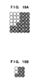
- Figs. 19B, 20B, 21B, and 22B show extracted Y pixels corresponding to the extracted chroma pixels.
- Fig. 19B shows an example of the extracted object when the chroma threshold value is low. That is, when a low threshold value is set, all pixels that extend across the boundary are extracted as those inside the object. In this case, since Y pixels are extracted from a range corresponding to extracted chroma pixels, an extraction result shown in Fig. 19A is obtained.
- Fig. 20B shows an example of the extracted object when the chroma threshold value is high. That is, when a high threshold value is set, all pixels that extend across the boundary are extracted as those falling outside the object. In this case, since Y pixels are similarly extracted from a range corresponding to extracted chroma pixels, an extraction result shown in Fig. 20A is obtained.
- boundary pixels can be set to fall within or outside the object.
- the threshold value is either low or high, the shape of the extraction result of Y pixels (Fig. 19A or 20A) becomes considerably different from the original shape shown in Fig. 17A.
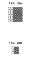
- Figs. 21A and 21B and Figs. 22A and 22B show examples of extracted Y and chroma objects when relatively high and low threshold values are set so that some of pixels which extend across the boundary fall within the object and some other pixels fall outside the object.
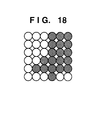
- the shapes of the extraction results of Y pixels shown in Figs. 21A and 22A become rather closer to an ideal pixel matrix shown in Fig. 18 than Figs. 19A and 20A, but are far from an ideal one.
- object extraction is done based on the chroma threshold value
- Y pixels are extracted depending on chroma pixel precision, it is difficult to extract Y pixels in an ideal shape.
- chroma threshold value setups but also threshold value setups based on Y pixel precision are required.
- This embodiment will exemplify a case wherein coding efficiency drop due to object extraction is avoided.
- Fig. 1 is a block diagram showing the overall arrangement of an image processing apparatus that implements object coding according to this embodiment.
- This apparatus receives chroma-subsampled image data.
- a threshold value discrimination unit 201 makes threshold value discrimination for the image data in units of Y and chroma data, and a shape data generation unit 202 and texture data generation unit 203 respectively generate shape and texture data on the basis of the discrimination results.
- Shape data is binary data that represents the shape of an object. For example, assume that a pixel which is located outside an object is a "0", and a pixel which is located inside the object is a "1".
- texture data is data that represents a pattern, and is composed of luminance (Y) and chroma (Cr, Cb) components.
- the size of the shape data which corresponds to the size of the input image is equal to that of luminance (Y) data in the input image data.
- An object of this embodiment is formed by a combination of these shape and texture data.
- threshold value discrimination unit 201 an object is extracted by the threshold value discrimination unit 201, shape data generation unit 202, and texture data generation unit 203. Note that detailed algorithms of threshold value discrimination and shape/texture data generation that pertain to object extraction will be described later.
- the object formed by the generated shape and texture data is encoded by an object encoding unit 204, thus achieving data compression of an object corresponding image.
- object encoding unit 204 encodes by exploiting interframe correlation
- motion vector data is encoded in addition to the shape and texture data.
- the multiplexed data is output as a bitstream of the object.
- the object extraction process in this embodiment will be explained below. Note that the object extraction process in this embodiment corresponds to a process for generating shape and texture data of an object.
- Fig. 2 is a flow chart showing the object extraction process in this embodiment.
- the sampling pattern of pixels of an input image has a matrix shown in Fig. 27, and the object shape to be extracted is as shown in Fig. 17.
- one macroblock of an object is comprised of four pixels of shape data, and four Y pixels and a pair of Cr and Cb pixels as texture data in the object extraction process of this embodiment, as shown in Fig. 29.
- step S101 a block consisting of four Y pixels (Y0 to Y3) and a pair of Cr and Cb pixels is generated. Then, pixels in the block of interest undergo threshold value discrimination. The shape and texture data that form an object of this embodiment are generated upon executing the threshold value discrimination process.
- step S102 If it is determined in step S102 that Cr and Cb do not fall within a predetermined threshold value range, it is determined before discrimination pertaining to Y pixels that pixels in the block of interest are located outside the object, and the flow advances to step S103. On the other hand, if Cr and Cb fall within the threshold value range, the flow advances to step S104 to discriminate Y pixels.
- step S104 It is checked in step S104 if any of Y0 to Y3 falls within a predetermined threshold value range. If none of those pixels fall within the range, it is determined that the pixels in the block of interest are located outside the object, and the flow advances to step S103.
- step S103 all four shape data corresponding to the block of interest are set at "0". In this case, since the block of interest falls outside the object, no texture data value is set.
- step S104 determines whether at least one of Y0 to Y3 falls within the predetermined threshold value range. If it is determined in step S104 that at least one of Y0 to Y3 falls within the predetermined threshold value range, the flow advances to step S105 to generate shape data, so that a pixel or pixels that falls or fall within the threshold value range is or are located inside the object, and pixels or a pixel that fall or falls outside the threshold value range are or is located outside the object.
- a Y value or values of the pixel or pixels which is or are located inside the threshold value range is or are set as Y texture data.
- chroma texture data is set. It is checked in step S107 if all the four Y pixels (Y0 to Y3) fall within the object. If all the four Y pixels are located inside the object, Cr and Cb values are set as chroma texture data in step S108. However, if at least one of the four pixels is located outside the object, it is determined that the block of interest forms an object boundary. In this embodiment, pixels which are located on the boundary are determined to be those located outside the object, and no chroma values are set for these pixels. In other word, chroma values of the object boundary are set as invalid data.
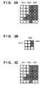
- Figs. 3A and 3B show examples of Y and chroma texture data which are set in this way
- Fig. 3C shows an example of shape data.
- blocks 301a to 301c correspond to each other, and so do blocks 302a to 302c and 303a to 303c.
- Black pixels in Fig. 3C are those which are determined to fall within the object, and black pixels in Figs. 3A and 3B are those set with significant texture data. In other words, white pixels in Fig. 3C are those falling outside the object, and white pixels in Figs. 3A and 3B are set with arbitrary values.
- Y texture data shown in Fig. 3A matches an ideal Y object extraction result shown in Fig. 18.
- Y texture data and shape data have the same shape (301a and 301c), and in chroma texture data, Cr and Cb values are set for only chroma pixels (corresponding to 303b) in correspondence with a block including all four pixels falling within the object in Y blocks, in other words, a block (303a) set with significant data. That is, if at least one of four Y pixels in a block falls outside the object, no chroma texture data is set (corresponding to 301b and 302b).
- step S109 shape and texture data for the entire image are generated, i.e., the object extraction process of this embodiment ends.
- shape data of the object is completely prepared.
- texture data those inside the object are set but those outside the object have arbitrary values.
- the object encoding unit 204 encodes the object after it sets texture data outside the object to improve coding efficiency.
- a method of setting texture data outside the object in this embodiment will be explained below.
- the object encoding unit 204 replaces values of pixels of texture data outside the object by those of neighboring pixels inside the object prior to encoding the object. This replacement process is called padding, which is done in units of macroblocks indicated by 1002 in Fig. 28.
- Pixel values inside the object are padded in texture data outside the object in the horizontal direction (horizontal padding), and pixel values inside the object are repetitively padded in texture data, which were not stuffed by horizontal padding, in the vertical direction (vertical padding).
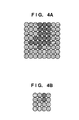
- Figs. 4A and 4B show examples of padding of Y and chroma macroblocks. Assume that a Y macroblock has an 8 ⁇ 8 pixel size, and a chroma macroblock has a 4 ⁇ 4 pixel size. In Figs. 4A and 4B, black pixels are those inside the object, horizontally striped pixels are those set by horizontal padding, and vertically striped pixels are those set by vertical padding.
- shape and texture data are completely prepared, and the object is completely extracted.
- the object encoding unit 204 encodes these texture and shape data and multiplexes them, thus outputting the multiplexed data as a bitstream of the extracted object.
- chroma data which extend across the boundary of an object are not included in the object, and chroma data on the object boundary are set with the same values as neighboring chroma data inside the object, thus improving coding efficiency.
- the second embodiment will exemplify a case wherein the object encoded by the first embodiment is decoded and is synthesized with a background image.
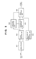
- Fig. 5 is a block diagram showing the overall arrangement of an image processing apparatus that implements object synthesis according to the second embodiment.
- This apparatus receives a bitstream which is obtained by multiplexing the encoded data of an object output from the image processing apparatus of the first embodiment, and encoded data of an arbitrary background image.
- the bitstream is input to a demultiplexer 501 to demultiplex the multiplexed data
- the encoded object data is input to an object decoding unit 502
- the encoded background data is input to a background image decoding unit 503.
- the object decoding unit 502 further demultiplexes the object data into shape and texture data, which are respectively decoded by a shape data generation unit 504 and texture data generation unit 505.
- a motion vector coding process is additionally done.
- An image synthesis unit 506 synthesizes the texture data of the object and the background image on the basis of the generated shape data, thus outputting a synthesized image.
- step S601 blocks are generated in correspondence with the subsampled shape.
- one texture data block is comprised of four Y pixels and a pair of Cr and Cb pixels.
- step S602 It is checked in step S602 if shape data (four pixels) corresponding to the block of interest falls within the object. That is, if all four shape data corresponding to the block of interest are "0"s, it is determined that they fall outside the object, and background image data values are selected as Y, Cr, and Cb values for all the pixels in the block of interest in step S603.
- step S604 if it is determined in step S604 that all four shape data are "1"s, it is determined that they fall within the object, and texture data of the object are selected as Y, Cr, and Cb values for all the pixels in the block of interest in step S605.
- step S604 If it is determined in step S604 that at least one shape data falls within the object, different processes are done for Y and chroma data.
- Y data according to the object shape, the texture data are selected and set for pixels inside the object and the background image data are selected and set for pixels outside the object in step S606.
- chroma data an arithmetic operation is made based on the object shape and surrounding pixel values to calculate chroma values in step S607.
- step S608 chroma values in the synthesized image are synthesized based on the chroma values calculated in step S607 and background values. The chroma arithmetic operation and chroma synthesis process will be described in detail later.
- step S609 the object synthesis process for the object of interest ends.
- Fig. 7 is a flow chart showing a chroma texture data calculation process in step S607.
- the chroma value of the pixel of interest is calculated on the basis of those of valid pixels around the pixel of interest.
- step S901 the chroma values of surrounding pixels are detected.
- Fig. 8 shows the positional relationship between target pixel A as the current pixel to be processed, and its surrounding pixels V0 to V7. An example for calculating the chroma value of target pixel A will be explained below.
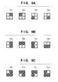
- step S902 A method of detecting valid combinations (chroma patterns) of surrounding chroma pixels will be explained below.
- Target chroma pixel A has corresponding shape data consisting of four pixels.
- shape data corresponding to black pixels in Figs. 9A to 9C
- background color corresponding to white pixels in Figs. 9A to 9C
- step S903 in Fig. 7 the distances between target pixel A and valid surrounding pixels are calculated.
- the central position of target pixel A corresponds to the barycenter of the shape pattern. Hence, the central position of target pixel A varies depending on the corresponding shape pattern.
- the interpixel distances may be held as a table to achieve high-speed processing. Since the distances are used to weight pixel values, if high precision is not required, high-speed arithmetic processing may be attained by rounding distance values to integers.
- the value of one of the valid surrounding pixels, which is closest to the target pixel may be determined to be the chroma value of the target pixel.
- step S608 in Fig. 6 The chroma synthesis process in step S608 in Fig. 6 will be described in detail below with reference to the flow chart shown in Fig. 10.
- step S608 the chroma value of target pixel A calculated based on equation (1) and that of a background pixel are synthesized on the basis of the ratio of intra-object pixels in a block.
- step S801 the ratio of background and object pixels of shape data in a given block is calculated.
- step S802 background and object data undergo chroma synthesis on the basis of the calculated ratio.
- the background ratio in a synthesized image is 3/4.
- “(number of shape data outside object)/(total number of shape data)” corresponds to the background ratio.
- total number of shape data in equation (2) is the number of shape data corresponding to one chroma pixel, and is "4" in the second embodiment.
- the value of chroma data which extends across the object boundary is calculated based on the chroma values of surrounding pixels, and the object and background image are synthesized on the basis of the ratio between the background and object in a given block, thus allowing natural color reproduction at the boundary between the background image and object image.
- the second embodiment has exemplified a case wherein a total of two images, i.e., one background image and one object, are synthesized. Even when there are a plurality of objects which overlap each other or contact each other at an identical position, the background ratio is calculated based on their shape data, thus achieving appropriate image synthesis.
- an object encoded by the first embodiment described above is decoded, and is synthesized with a background image.
- the apparatuses described in the first and second embodiments may be combined to obtain a single image processing apparatus. In this case, data need not be encoded or decoded. More specifically, image data including an object and background image data are parallelly input to the apparatus, the object is extracted from the image data by the method described in the first embodiment, and that object is synthesized with the background image data by the method described in the second embodiment, thus outputting a synthesized image.
- the third embodiment will exemplify a case wherein coding efficiency drop is avoided by appropriately setting chroma values at object boundaries upon object extraction.
- An object is extracted in the form of a bounding box 1001, as shown in Fig. 28.
- "padding" for replacing texture data outside the object by those inside the object is executed to improve the coding efficiency. This process is done in units of macroblocks, and one of the following three methods is used depending on the state of the object:
- Boundary macroblock padding (1) will be explained below with reference to Figs. 23 and 24.
- Fig. 23 is a flow chart showing boundary macroblock padding for Y data. Since the resolution of shape data matches that of Y data, discrimination can be made in units of pixels.
- step S1401 It is checked in step S1401 if shape data of interest is located outside the object. If YES in step S1401, the shape data of interest is determined to be padding target data in step S1402. On the other hand, if it is determined in step S1401 that the shape data of interest is located inside the object, texture data (image data of the object) is determined as output data in step S1403. Upon completion of discrimination for all pixels in a given macroblock (S1404), padding is done for the padding target data. In step S1405, horizontal padding is executed. In this process, data outside the object are padded by data inside the object in the horizontal direction. Then, pixels which were not stuffed by horizontal padding are stuffed by vertical padding in step S1406.
- Fig. 25 shows an example of an ideal shape indicated by a boundary macroblock
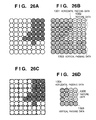
- Figs. 26A and 26B show padding examples of the boundary macroblock.
- the macroblock size in this case is 8 ⁇ 8 pixels for the sake of simplicity.
- Fig. 26A shows an example of shape data in the boundary macroblock.
- full circles indicate pixels inside the object, and open circles indicate those outside the object.
- Fig. 26B shows Y data after padding at this time.
- pixels Y1 to Y19 are texture data 1302
- horizontally striped pixels are horizontal padding data 1301
- vertically striped pixels are vertical padding data 1303.
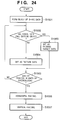
- Fig. 24 is a flow chart showing the boundary macroblock padding process for chroma data.
- chroma data There are two kinds of chroma data, i.e., Cb and Cr data, but since the same process is done for these data, the following description will be given without distinguishing them. Since both the horizontal and vertical resolutions of chroma data are half those of shape data, one chroma pixel is discriminated per four pixels of shape data.
- step S1501 a block of four pixels of shape data is formed. It is then checked in step S1502 if all four shape data in the block of interest are located outside the object. If YES in step S1502, that block is determined to be padding target data in step S1503.
- step S1502 determines whether at least one shape data is located inside the object.
- texture data is determined to be output data in step S1504.
- padding is done for padding target data.
- Horizontal padding is executed first in step S1506, and pixels which were not stuffed by horizontal padding are then stuffed by vertical padding in step S1507.
- Fig. 26C shows an example of blocks of shape data formed in the boundary macroblock.
- Fig. 26D shows chroma data after padding at that time.
- pixels C1 to C7 are texture data 1305, horizontally striped pixels are horizontal padding data 1304, and vertically striped pixels are vertical padding data 1306.
- Macroblock padding (2) when shape data is located outside the object and neighbors a boundary macroblock will be explained below.
- This padding process is called expanded padding.
- a reference macroblock the neighboring direction of a boundary macroblock is checked in the priority order of left, upper, right, and lower. If a neighboring boundary macroblock is found, data at the boundary position are repetitively copied in the horizontal or vertical direction.
- Macroblock padding process (3) other than processes (1) and (2) will be explained below. That is, this process is done when shape data is located outside the object and does not neighbor any boundary macroblock, and is called constant value padding. In this process, all data in a given macroblock are set at a constant value "128".
- the coding efficiency can be improved compared to a case wherein the object boundary has an edge. Since the decoder side executes a process reverse to that on the encoder, the padded data are replaced by background data.
- Fig. 26C shows an example of blocks of shape data formed in the boundary macroblock
- Fig. 26D shows chroma data after padding at that time.
- pixels C1, C3, C5, C6, and C7 may suffer the aforementioned problem.
- chroma data is obtained by mixing colors inside and outside the object at 50% each.
- the ratio of data inside and outside the object is 3 : 1
- the color inside the object is 75% and the influence is small.
- the ratio of data inside and outside the object is 1 : 3
- the color inside the object is only 25%. This poses a serious problem on coding efficiency and color reproducibility.
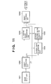
- Fig. 11 is a block diagram showing the overall arrangement of an image processing apparatus that implements object encoding according to the third embodiment.
- An image input unit 1201 performs data matching in correspondence with the image format to be processed. For example, when the input image is an analog signal, the image input unit 1201 performs A/D conversion; when the input image is RGB data, it performs YCbCr conversion. Alternatively, the image input unit 1201 performs processes such as 4 : 2 : 0 format conversion by a chroma subsampling process.
- An object extraction unit 1202 detects a region where the object is present, and generates shape data.
- the object extraction unit 1202 forms a bounding box on the basis of the shape defined by the shape data, and generates macroblocks.
- object extraction methods a threshold value process using chroma-keying, a method using a dynamic edge model, and the like are available. However, since this embodiment is independent from such extraction methods, object extraction may be done by any method.
- a Y padding block generation unit 1203 implements padding of Y data in units of macroblocks. If all data within a given macroblock are located inside the object, no padding is required. That is, padding is done for only boundary macroblocks, macroblocks to be subjected to expanded padding, and macroblocks to be subjected to constant value padding.
- a chroma data generation unit 1204 generates new data for boundary macroblocks in which chroma data extend across the boundary of the object. The process in the chroma data generation unit 1204 will be described in detail later.
- a chroma padding block generation unit 1205 implements padding of chroma data in units of macroblocks. If all data within a given macroblock are located inside the object, no padding is required. That is, padding is done for only boundary macroblocks, macroblocks to be subjected to expanded padding, and macroblocks to be subjected to constant value padding. Note that the data generated by the chroma data generation unit 1204 are used in boundary macroblocks in which chroma data extend across the boundary of the object. The process in the chroma padding block generation unit 1205 will be described in detail later.
- an object encoding unit 1206 executes an encoding process.
- Y (luminance) and chroma (color difference) texture data undergo processes such as DCT, quantization, variable-length coding, and the like.
- Shape data undergo arithmetic coding called CAE (Context-based Arithmetic Encoding). Note that the object encoding unit 1206 generates a stream of one video object, and multiplexing is required after this unit if a plurality of streams are to be processed.
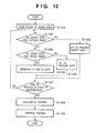
- Chroma data generation and padding process in the chroma data generation unit 1204 and chroma padding block generation unit 1205 will be described in detail below with reference to the flow chart shown in Fig. 12.
- Chroma data in this embodiment are processed in units of macroblocks in accordance with the flow chart shown in Fig. 12.
- step S1101 blocks are formed in units of four pixels of shape data. It is then checked in step S1102 if all shape data in the block of interest are located outside the object. If YES in step S1102, that block is set as padding target data in step S1103.
- step S1104 if at least one shape data is located inside the object, it is checked in step S1104 if all the shape data are located inside the object. If YES in step S1104, that block is set as texture data (chroma data itself of the object) in step S1105.
- chroma data extends across the boundary of the object.
- chroma data is generated in step S1106. Since the details of the chroma data generation process in step S1106 is the same as the chroma data setup process at the object boundary, that has been explained in the second embodiment with reference to Figs. 7 to 9C, a detailed description thereof will be omitted. That is, the chroma value of a target pixel is calculated as the average of chroma values of valid surrounding pixels, which are weighted based on their distances.
- the chroma value of the target pixel may be set to be equal to the value of one of the valid surrounding pixels, which is closest to the target pixel.
- the value of pixel C1 becomes equal to that of C2, and all horizontal padding data in this line become equal to C2.
- the value of pixel C3 becomes equal to that of C4, and all horizontal padding data in this line become equal to C4. In this manner, further improvement of the coding efficiency can be expected.
- step S1107 It is checked in step S1107 if the processes are complete for all pixels in a given macroblock, and the processes in steps S1102 to S1107 are repeated until they are completed for all the pixels.
- padding is executed for padding target data set in step S1103. That is, horizontal padding is done in step S1108, and vertical padding is then done in step S1109. With this process, all chroma data in the macroblock are determined.
- chroma data can be generated without including any color outside the object. Hence, since the gap between chroma data that extends across the object boundary and neighboring chroma data inside the object can be reduced, the coding efficiency in the object encoding unit 208 can be improved.
- the fourth embodiment will exemplify a case wherein the object encoded by the third embodiment is decoded and is synthesized with a background image.
- a general object synthesis process for synthesizing an object extracted according to MPEG4 with another image (background data) will be described in detail below.
- the object synthesis process can basically take a procedure reverse to the object extraction process. In this embodiment, only the synthesis process of a boundary macroblock will be explained.
- Fig. 13 is a flow chart showing an example of the Y data synthesis process. Since the resolution of shape data matches that of Y data, discrimination can be made in units of pixels. It is checked in step S1601 if shape data is located outside the object. If YES in step S1601, background data is selected in step S1602. On the other hand, if NO in step S1601, texture data (object data) is directly selected in step S1603. Upon completion of the process for all data in a given macroblock (S1604), this synthesis process ends.
- Fig. 14 is a flow chart showing an example of the chroma data synthesis process. Since both the horizontal and vertical resolutions of chroma data are half those of shape data, one chroma pixel is discriminated per four pixels of shape data.
- step S1701 a block of four pixels of shape data is formed. It is then checked in step S1702 if all four shape data in the block of interest are located outside the object. If YES in step S1702, background data is selected in step S1703. On the other hand, if it is determined in step S1702 that at least one shape data is located inside the object, texture data (object data) is directly selected in step S1704. Upon completion of discrimination for all pixels in a given macroblock (S1705), this synthesis process ends.
- the decoder side synthesizes texture data by a process reverse to that on the encoder side, padding data are replaced by background data on the decoder side.
- Fig. 15 is a block diagram showing the overall arrangement of an image processing apparatus that decodes and synthesizes an object in the fourth embodiment.
- a demultiplexer 1801 demultiplexes a multiplexed bitstream.
- the multiplexed bitstream contains two types of data, i.e., data pertaining to a background image, and data pertaining to an image object.
- the stream data demultiplexed by the demultiplexer 1801 are respectively sent to an object decoding unit 1802 and background image decoding unit 1803.
- the object decoding unit 1802 decodes texture data in units of macroblocks via processes such as variable-length decoding, dequantization, inverse DCT, and the like. Also, the unit 1802 decodes shape data in units of macroblocks via processes such as arithmetic decoding and the like.
- the background image decoding unit 1803 decodes background image data via the same decoding processes.
- a Y data selection unit 1804 selects based on the value of shape data if Y data of the object or background is used as texture data.
- a chroma data generation unit 1805 generates new chroma data for boundary macroblocks in which chroma data extend across the boundary of the object. The process in the chroma data generation unit 1805 will be described in detail later.
- a chroma data selection unit 1806 selects based on the value of shape data if chroma data of the object or background, or data generated by the chroma data generation unit 1805 is used as texture data. The process in the chroma data selection unit 1806 will be described in detail later.
- An image output unit 1807 executes a process for converting data synthesized upon selection in the Y data selection unit 1804 and chroma data selection unit 1806 into an output format.
- the unit 1807 executes processes such as an upsampling process of subsampled data, RGB conversion of YCbCr data, D/A conversion upon generating an analog output, and the like.
- Fig. 16 is a flow chart showing especially the process that pertains to chroma data in the object synthesis process in the fourth embodiment.
- step S1901 a block formation process for forming blocks in units of four pixels of shape data is executed. It is then checked in step S1902 if all four shape data in the block of interest are located outside the object. If YES in step S1902, chroma data of the background is selected in step S1903. On the other hand, if it is determined in step S1902 that at least one shape data is located inside the object, it is checked in step S1904 if all the shape data are located within the object. If YES in step S1904, texture data (chroma data itself of the object) is selected in step S1905.
- step S1907 It is checked in step S1907 if the processes are complete for all pixels in a given macroblock, and the processes in steps S1902 to S1907 are repeated until they are completed for all the pixels. Upon completion of the processes for all the pixels in the macroblock, all chroma data in the macroblock are determined.
- chroma data synthesis process in step S1906 above is done by the chroma data generation unit 1805. Since this synthesis process is done on the basis of the ratio between the object and background in a given block in the same manner as the process that has been explained in the second embodiment using Fig. 10, a detailed description thereof will be omitted. That is, chroma data are synthesized based on equation (2).
- the fourth embodiment can be practiced independently of the third embodiment described above. Also, by adopting the third embodiment on the object encoder side, and the fourth embodiment on the decoder side, color reproducibility after synthesis can be further improved.
- the present invention may be applied to either a system constituted by a plurality of devices (e.g., a host computer, an interface device, a reader, a printer, and the like), or an apparatus consisting of a single equipment (e.g., a copying machine, a facsimile apparatus, or the like).
- a system constituted by a plurality of devices (e.g., a host computer, an interface device, a reader, a printer, and the like), or an apparatus consisting of a single equipment (e.g., a copying machine, a facsimile apparatus, or the like).
- the objects of the present invention are also achieved by supplying a carrier medium, which carries program code of a software program that can implement the functions of the above-mentioned embodiments to the system or apparatus, and reading out and executing the program code stored in the storage medium by a computer (or a CPU or MPU) of the system or apparatus.
- the program code itself read out from the storage medium implements the functions of the above-mentioned embodiments
- the carrier medium which carries the program code constitutes the present invention.
- the carrier medium for supplying the program code for example, a floppy disk, hard disk, optical disk, magneto-optical disk, CD-ROM, CD-R, magnetic tape, nonvolatile memory card, ROM, signal (e.g. over a network such as the Internet), and the like may be used.
- the functions of the above-mentioned embodiments may be implemented not only by executing the readout program code by the computer but also by some or all of actual processing operations executed by an OS (operating system) running on the computer on the basis of an instruction of the program code.
- OS operating system
- the functions of the above-mentioned embodiments may be implemented by some or all of actual processing operations executed by a CPU or the like arranged in a function extension board or a function extension unit, which is inserted in or connected to the computer, after the program code read out from the storage medium is written in a memory of the extension board or unit.
- the carrier medium When the present invention is applied to the carrier medium, the carrier medium carries program codes corresponding to the aforementioned flow charts.
Landscapes
- Engineering & Computer Science (AREA)
- Multimedia (AREA)
- Signal Processing (AREA)
- Physics & Mathematics (AREA)
- General Physics & Mathematics (AREA)
- Theoretical Computer Science (AREA)
- Compression Or Coding Systems Of Tv Signals (AREA)
Applications Claiming Priority (4)
| Application Number | Priority Date | Filing Date | Title |
|---|---|---|---|
| JP34218398 | 1998-12-01 | ||
| JP10342183A JP2000175217A (ja) | 1998-12-01 | 1998-12-01 | 画像処理装置及びその方法、及び画像処理システム |
| JP8046199A JP2000278709A (ja) | 1999-03-24 | 1999-03-24 | 画像処理装置及びその方法、及び画像処理システム |
| JP8046199 | 1999-03-24 |
Publications (2)
| Publication Number | Publication Date |
|---|---|
| EP1006482A2 true EP1006482A2 (fr) | 2000-06-07 |
| EP1006482A3 EP1006482A3 (fr) | 2005-08-10 |
Family
ID=26421469
Family Applications (1)
| Application Number | Title | Priority Date | Filing Date |
|---|---|---|---|
| EP99309591A Withdrawn EP1006482A3 (fr) | 1998-12-01 | 1999-11-30 | Codage séparé d' objets dans une image et de leurs limites |
Country Status (2)
| Country | Link |
|---|---|
| US (1) | US6636644B1 (fr) |
| EP (1) | EP1006482A3 (fr) |
Families Citing this family (18)
| Publication number | Priority date | Publication date | Assignee | Title |
|---|---|---|---|---|
| US6952501B2 (en) * | 2000-02-24 | 2005-10-04 | Canon Kabushiki Kaisha | Image processing apparatus, image encoding apparatus, and image decoding apparatus |
| CA2423179A1 (fr) * | 2000-09-21 | 2002-03-28 | Digital Network Shopping, Llc | Procede et appareil permettant d'effectuer des achats par voie numerique |
| US6842177B2 (en) * | 2001-12-14 | 2005-01-11 | University Of Washington | Macroblock padding |
| US20050094729A1 (en) * | 2003-08-08 | 2005-05-05 | Visionflow, Inc. | Software and hardware partitioning for multi-standard video compression and decompression |
| CA2557533A1 (fr) | 2004-02-27 | 2005-09-09 | Td Vision Corporation S.A. De C.V. | Procede et systeme de codification numerique d'images video 3d stereoscopiques |
| KR101177663B1 (ko) * | 2004-02-27 | 2012-09-07 | 티디비전 코포레이션 에스.에이. 데 씨.브이. | 입체적 3d-비디오 이미지 디지털 디코딩 시스템 및 방법 |
| JP4114885B2 (ja) * | 2005-10-31 | 2008-07-09 | 松下電器産業株式会社 | 画像符号化装置、方法、及びプログラム |
| US7385611B1 (en) * | 2005-12-07 | 2008-06-10 | Nvidia Corporation | Decompression of block encoded texture data |
| JP4890973B2 (ja) | 2006-06-29 | 2012-03-07 | キヤノン株式会社 | 画像処理装置、画像処理方法、画像処理プログラム及び記憶媒体 |
| JP4890974B2 (ja) * | 2006-06-29 | 2012-03-07 | キヤノン株式会社 | 画像処理装置、及び画像処理方法 |
| JP4926568B2 (ja) * | 2006-06-29 | 2012-05-09 | キヤノン株式会社 | 画像処理装置、画像処理方法、及び画像処理プログラム |
| US8249365B1 (en) * | 2009-09-04 | 2012-08-21 | Adobe Systems Incorporated | Methods and apparatus for directional texture generation using sample-based texture synthesis |
| US8599219B2 (en) | 2009-09-18 | 2013-12-03 | Adobe Systems Incorporated | Methods and apparatuses for generating thumbnail summaries for image collections |
| US8619098B2 (en) | 2009-09-18 | 2013-12-31 | Adobe Systems Incorporated | Methods and apparatuses for generating co-salient thumbnails for digital images |
| US8331684B2 (en) * | 2010-03-12 | 2012-12-11 | Sony Corporation | Color and intensity based meaningful object of interest detection |
| US8861868B2 (en) | 2011-08-29 | 2014-10-14 | Adobe-Systems Incorporated | Patch-based synthesis techniques |
| US10142613B2 (en) * | 2015-09-03 | 2018-11-27 | Kabushiki Kaisha Toshiba | Image processing apparatus, image processing system, and image processing method |
| JP7275924B2 (ja) * | 2019-06-28 | 2023-05-18 | セイコーエプソン株式会社 | 液体吐出装置、駆動回路、及び集積回路 |
Family Cites Families (13)
| Publication number | Priority date | Publication date | Assignee | Title |
|---|---|---|---|---|
| US4602286A (en) * | 1982-01-15 | 1986-07-22 | Quantel Limited | Video processing for composite images |
| JPH05153618A (ja) * | 1991-11-26 | 1993-06-18 | Sanyo Electric Co Ltd | 映像再生装置 |
| US5812787A (en) * | 1995-06-30 | 1998-09-22 | Intel Corporation | Video coding scheme with foreground/background separation |
| US5883678A (en) * | 1995-09-29 | 1999-03-16 | Kabushiki Kaisha Toshiba | Video coding and video decoding apparatus for reducing an alpha-map signal at a controlled reduction ratio |
| KR100209412B1 (ko) * | 1996-05-10 | 1999-07-15 | 전주범 | 비디오 신호의 유호 색차 성분 부호화 방법 |
| KR100501902B1 (ko) * | 1996-09-25 | 2005-10-10 | 주식회사 팬택앤큐리텔 | 영상정보부호화/복호화장치및방법 |
| EP0833521A3 (fr) * | 1996-09-30 | 1999-09-15 | Hyundai Electronics Industries Co., Ltd. | Appareil et méthode de codage et décodage d'informations d'image |
| US6035060A (en) * | 1997-02-14 | 2000-03-07 | At&T Corp | Method and apparatus for removing color artifacts in region-based coding |
| US6208693B1 (en) * | 1997-02-14 | 2001-03-27 | At&T Corp | Chroma-key for efficient and low complexity shape representation of coded arbitrary video objects |
| US5978034A (en) * | 1997-02-20 | 1999-11-02 | Sony Corporation | Moving picture encoding method and apparatus, moving picture decoding method and apparatus and recording medium |
| US5978510A (en) * | 1997-03-20 | 1999-11-02 | Hyundai Electronics Industries Co., Ltd. | Method and apparatus for predictively coding contour of video signal |
| EP0921684B1 (fr) * | 1997-12-02 | 2005-11-02 | Daewoo Electronics Corporation | Méthode et appareil pour encoder une information objet d'un plan vidéo objet |
| CA2260578C (fr) * | 1998-01-27 | 2003-01-14 | At&T Corp. | Methode et dispositif de codage d'information video de forme et de texture |
-
1999
- 1999-11-30 EP EP99309591A patent/EP1006482A3/fr not_active Withdrawn
- 1999-12-01 US US09/452,818 patent/US6636644B1/en not_active Expired - Fee Related
Also Published As
| Publication number | Publication date |
|---|---|
| EP1006482A3 (fr) | 2005-08-10 |
| US6636644B1 (en) | 2003-10-21 |
Similar Documents
| Publication | Publication Date | Title |
|---|---|---|
| EP1006482A2 (fr) | Codage séparé d' objets dans une image et de leurs limites | |
| US10904570B2 (en) | Method for encoding/decoding synchronized multi-view video by using spatial layout information and apparatus of the same | |
| CN110753223B (zh) | 视频解码方法及装置 | |
| KR101768857B1 (ko) | 다시야 비디오 코딩에서 로우 다이내믹 레인지 이미지들로부터 하이 다이내믹 레인지 이미지들의 생성 | |
| US20210092367A1 (en) | Apparatus and method for video encoding or decoding | |
| CN111630571B (zh) | 处理点云 | |
| KR100292160B1 (ko) | 화상 합성 방법, 화상 합성 장치, 및 데이터 기록 매체 | |
| US20130222377A1 (en) | Generation of depth indication maps | |
| Ebrahimi | MPEG-4 video verification model: A video encoding/decoding algorithm based on content representation | |
| US6128041A (en) | Method and apparatus for binary shape encoding | |
| KR20000068737A (ko) | 영상 신호를 멀티플렉싱하는 방법 및 시스템, 영상 신호를 디멀티플렉싱하는 방법 및 시스템 및, 전송 매체 | |
| JPH10155148A (ja) | 映像情報符号化/復号化装置および方法 | |
| CN117560487A (zh) | 解码设备、编码设备及发送图像的数据的设备 | |
| US20200267385A1 (en) | Method for processing synchronised image, and apparatus therefor | |
| CN116527892A (zh) | 解码设备、编码设备和数据发送设备 | |
| US6577352B1 (en) | Method and apparatus for filtering chrominance signals of image | |
| JPH10336673A (ja) | 映像信号符号化システムにおける縁部検出方法及びその装置 | |
| CN115136608A (zh) | 基于虚拟边界的图像编码装置和方法 | |
| US7899112B1 (en) | Method and apparatus for extracting chrominance shape information for interlaced scan type image | |
| CN118541976A (zh) | 图像编码/解码方法和设备以及具有存储在其上的比特流的记录介质 | |
| CN115152214A (zh) | 基于画面划分的图像编码装置和方法 | |
| CN114982242A (zh) | 发信号通知图片分割信息的方法和设备 | |
| US20260045014A1 (en) | Decoder, encoder, bitstream generator, decoding method, and encoding method | |
| JP2000278709A (ja) | 画像処理装置及びその方法、及び画像処理システム | |
| JP2000175217A (ja) | 画像処理装置及びその方法、及び画像処理システム |
Legal Events
| Date | Code | Title | Description |
|---|---|---|---|
| PUAI | Public reference made under article 153(3) epc to a published international application that has entered the european phase |
Free format text: ORIGINAL CODE: 0009012 |
|
| AK | Designated contracting states |
Kind code of ref document: A2 Designated state(s): AT BE CH CY DE DK ES FI FR GB GR IE IT LI LU MC NL PT SE |
|
| AX | Request for extension of the european patent |
Free format text: AL;LT;LV;MK;RO;SI |
|
| RIC1 | Information provided on ipc code assigned before grant |
Ipc: 7H 04N 7/24 B Ipc: 7H 04N 7/26 B Ipc: 7G 06T 9/00 A |
|
| PUAL | Search report despatched |
Free format text: ORIGINAL CODE: 0009013 |
|
| AK | Designated contracting states |
Kind code of ref document: A3 Designated state(s): AT BE CH CY DE DK ES FI FR GB GR IE IT LI LU MC NL PT SE |
|
| AX | Request for extension of the european patent |
Extension state: AL LT LV MK RO SI |
|
| 17P | Request for examination filed |
Effective date: 20060210 |
|
| AKX | Designation fees paid |
Designated state(s): DE FR GB IT NL |
|
| 17Q | First examination report despatched |
Effective date: 20060523 |
|
| STAA | Information on the status of an ep patent application or granted ep patent |
Free format text: STATUS: THE APPLICATION HAS BEEN WITHDRAWN |
|
| 18W | Application withdrawn |
Effective date: 20130404 |