EP1006494B1 - Module de stockage d'articles pour distributeur automatique - Google Patents
Module de stockage d'articles pour distributeur automatique Download PDFInfo
- Publication number
- EP1006494B1 EP1006494B1 EP19980122713 EP98122713A EP1006494B1 EP 1006494 B1 EP1006494 B1 EP 1006494B1 EP 19980122713 EP19980122713 EP 19980122713 EP 98122713 A EP98122713 A EP 98122713A EP 1006494 B1 EP1006494 B1 EP 1006494B1
- Authority
- EP
- European Patent Office
- Prior art keywords
- article
- pusher
- rack
- storage device
- articles
- Prior art date
- Legal status (The legal status is an assumption and is not a legal conclusion. Google has not performed a legal analysis and makes no representation as to the accuracy of the status listed.)
- Expired - Lifetime
Links
Images





Classifications
-
- G—PHYSICS
- G07—CHECKING-DEVICES
- G07F—COIN-FREED OR LIKE APPARATUS
- G07F11/00—Coin-freed apparatus for dispensing, or the like, discrete articles
- G07F11/02—Coin-freed apparatus for dispensing, or the like, discrete articles from non-movable magazines
- G07F11/38—Coin-freed apparatus for dispensing, or the like, discrete articles from non-movable magazines in which the magazines are horizontal
- G07F11/42—Coin-freed apparatus for dispensing, or the like, discrete articles from non-movable magazines in which the magazines are horizontal the articles being delivered by motor-driven means
Definitions
- This invention relates to an article storage device for a vending machine, and more particularly to an article storage device of this kind which stores a large number of articles in a manner placed one after another, and pushes out the articles one by one by means of a pusher to dispense them for vending.
- the present applicant proposed this kind of article storage device for a vending machine e.g. in Japanese Patent Application JP-A-10255154 (basis for preamble of claim 1).
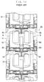
- the article storage device 50 includes a plurality of article racks 51 arranged one above another, each of which is formed with a pair of right and left article passages 52. Article S are stored in these article passages 52.
- Each article rack 51 is mounted in a body of the vending machine, not shown, such that it can be moved in a front-rear direction by means of rollers 53, ball bearings 54, etc. and that it can be drawn out of the machine body.
- the article rack 51 has a rack opening/closing plate 55 mounted at a front end thereof for opening/closing the article passage 52, and a pair of pushers 56 each movably mounted behind the rack opening/closing plate 55 in a manner corresponding to the respective article passages 52.
- a large number of articles S are stored in the article passages 52 in a manner placed one after another between the rack opening/closing plate 55 and each of the pushers 56.
- the pushers 56 are each slidably mounted on a guide rod 57 arranged in a front-rear direction under an upper article rack 51. While the pusher 56 can slide forward and backward along the guide rod 57, it is always urged forward by helical tension springs 59 connected thereto by a wire 58, etc.
- each pusher 56 is supported by a corresponding guide rod 57 in a manner hung therefrom, and hence the pusher 56 is brought into contact with the rearmost article S at a lower point than a supporting point at which the pusher 56 is supported by the guide rod 57. Therefore, moment which acts on a lower portion of the pusher 56 to turn the pusher 56 backward about the supporting point is produced by a reaction force from the rearmost article S generated when the pusher 56 pushes the articles S forward, and by an urging force applied via the articles S to the pusher 56 when the article rack 51 is pushed back after being replenished. This causes the pusher 56 to be inclined with respect to the guide rod 57, whereby sliding (frictional) resistance to the movement of the pusher 56 on the guide rod 57 is increased.
- the sliding resistance is not significant so that no serious problem occurs.
- articles S are heavy, or when frictional resistance between articles S and the article passage 52 is high, the sliding resistance between the pusher 56 and the guide rod 57 is much increased, causing a large loss of the urging force of the pusher 56.
- This demands a large urging force of the helical tension springs 59 for pushing the articles S forward for delivery.
- the urging force of the helical tension springs 59 is increased, it causes an increase in resistance produced when the article rack 51 is pushed back into the machine body after being replenished with articles S. This seriously affects ease of handling of the article rack 51.
- the urging force of the articles S acts on the pusher 56 to increase the inclination of the pusher 56 with respect to the guide rod 57.
- the sliding resistance between the pusher 56 and the guide rod 57 is increased, causing a large loss of operating force and hence also affecting the ease of handling of the article rack 51.
- the guide rod 57 is very thin and long, and cannot avoid sagging to some degree, which also causes an increase in the sliding resistance of the pusher 56 on the rod 57.
- the present invention provides an article storage device for a vending machine, including an article rack provided within a body of the vending machine in a manner such that the article rack can be moved in a front-rear direction and drawn forward out of the body of the vending machine, the article rack having an article passage formed therein for receiving a large number of articles one behind another, a rack opening/closing member provided at a front end of the article rack, for opening a dispensing opening of the article passage during a vending operation, and closing the dispensing opening except during the vending operation, a pusher inserted in the article passage, for pushing forward the articles received in the article passage, a guide member arranged above the article rack in a manner such that the guide member extends in the front-rear direction, for guiding the pusher in the front-rear direction, and urging means for urging the pusher forward.
- the article storage device is characterized in that the guide member comprises a body plate extending vertically, and a guide portion integrally formed with the body plate, the guide portion having a pair of guide protrusions laterally spaced from the body plate and being vertically opposed to each other, and the pusher comprises a pusher body inserted into the article passage, and a pair of front and rear rollers each formed with a U-shaped groove and attached to an upper side of the pusher body in a manner rotatable about respective horizontal axes, the pusher being mounted between the vertically opposed guide protrusions of the guide portion of the guide member, with the U-shaped groove of each of the rollers being fitted on the vertically opposed guide protrusions.
- this article storage device for a vending machine
- the article rack when the article rack is to be replenished with articles, it is drawn forward out of the machine body, and then the articles are placed one behind another in the article passage in a state of the pusher being held within the machine body.
- the article rack After the replenishment, the article rack is pushed back into the machine body, whereby a rearmost one of the articles placed in the article passage pushes the pusher back to its extreme backward position.
- the numerous articles are made ready for vending in a state sandwiched between the rack opening/closing member in its closed position and the pusher body of the pusher urged forward by the urging means.
- the rack opening/closing member opens the dispensing opening of the article passage, whereby a foremost one of the articles placed in the article passage is dispensed from the article rack.
- the pusher moves backward along the guide member after replenishment of articles, with the pusher body thereof being pushed by the articles in the article passage, while it moves forward along the guide member during a vending operation, with the pusher body pushing the articles.
- the pair of front and rear rollers mounted on the pusher body roll on the guide member, so that moment produced by a pushing force applied between the pusher body and the articles to act on the pusher body is absorbed by the rollers, whereby frictional resistance to the movement of the pusher on the guide member is considerably reduced.
- the urging force of the urging means required for moving the pusher forward can be reduced, which makes it possible to enhance ease of handling of the article rack after replenishment of articles.
- each of the rollers is mounted on the guide member in a manner rotatable about its horizontal axis and rolls in a state of the U-shaped groove thereof being engaged with the upper and lower guide protrusions, it is possible to employ a guide member having a smaller width (or side-to-side dimension) compared with a case in which the whole of each roller is received in the guide member.
- the guide member can also serve as a partition wall for separating the upper spaces of the article passage from each other, so that the guide member having a reduced width allows larger space to be used for storing articles.
- the each of the rollers is equipped with a bearing.
- direct torque transmission between each of the rollers and its rotational shaft is prevented by the bearing, and frictional resistance produced between them during rotation of the roller is reduced to near zero, whereby the frictional resistance to the movement of the pusher on the guide member is further reduced.
- the pusher further comprises an auxiliary roller mounted on the pusher body at a location below the rollers, for rotation about a vertical axis of the auxiliary roller to roll on a side face of the body plate of the guide member.
- the auxiliary roller mounted on a lower side face of the pusher body rolls about its vertical axis to move on the body plate of the guide member in rolling contact therewith. Therefore, the urging face of the pusher body in contact with the articles can maintain perpendicularity with respect to a plane in which the guide member extends, whereby the frictional resistance to the movement of the pusher can be further decreased.
- the guide member is made of an extrusion molded article of aluminum.
- the guide member can have an increased strength and dimensional accuracy.
- the increased dimensional accuracy contributes to further reduction of the frictional resistance to the movement of the pusher on the guide member.
- the guide member is subjected to surface treatment by using alumite.
- the smoothness of the guide member is enhanced, whereby the frictional resistance to the movement of the pusher on the guide member is further decreased.
- a vending machine 2 to which the present invention is applied is a so-called see-through vending machine which allows vendible articles actually contained therein, such as canned or packed beverages, to be viewed from outside.
- the vending machine 2 is comprised of a machine body 3 having an article storage device 1 of the invention installed therein, a main door 4 mounted on the front of the machine body 3, and a transparent heat insulating door 5 interposed between the main door 4 and the machine body 3.
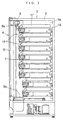
- FIGS. 2 and 3 mounted in a storage box 3a of the machine body 3 are twenty four article racks 10 which are arranged in eight vertical layers and three horizontal rows. Each of the article racks 10 stores articles S of the same kind.
- the selection buttons 4b each having a number identical to one assigned to a corresponding one of the article racks 10 are arranged in the form of a matrix corresponding to the array of the article racks 10.
- This construction permits viewing of the articles S in the article racks 10 through the front window 4d and the transparent heat insulating door 5.
- a user can select and buy a desired article S by putting cash into any one of the slots 4a and then pushing a selection button 4b corresponding to an article rack 10 storing the desired article.
- each of the article racks 10 is mounted on a corresponding one of the shelves 16 such that it can move in a front-rear direction thereon.
- Each article rack 10 is received in the machine body 3, as shown in FIG. 3, when the machine 1 is ready for vending the articles S.
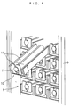
- the rack 10 is required to be replenished with articles S, it is drawn forward out of the machine body 3 as shown in FIG. 4.
- each of the article racks 10 is formed with a pair of right and left article passage 11, 11 extending in parallel with each other in a front-rear direction.
- each of the article passage 11, 11 a large number of articles S of the same kind are placed one behind another in a horizontal row each in an upright position.
- the storage box 3a has an elevator 6 arranged in a space in front of the array of article racks 10 such that the elevator 6 can move up and down between the ceiling of the storage box 3a and a shutter 3b arranged on the bottom of the same.
- the elevator 6 carries an article S dispensed from one of the article passages 11 on a carrier plate 6a down to the vicinity of the shutter 3b, and delivers the article S via the shutter 3b and the product outlet 4c.
- each of the article racks 10 has a front end thereof provided with a rack opening/closing mechanism 7 for opening/closing the article passage 11.
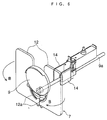
- the rack opening/closing mechanism 7 is comprised of a pair of right and left rack opening/closing plates (rack opening/closing members) 12, 12, a spring, not shown, and an stopper plate 9 mounted in front of the pair of rack opening/closing plates 12 in a manner slidable on front surfaces thereof.
- the rack opening/closing plates 12 are each mounted at the extreme front end of a corresponding one of the article racks 10 such that it can pivot about inside end portions thereof serving as a vertical axis of the plate 12.
- the rack opening/closing plate 12 can pivotally move between a closed position thereof for closing a dispensing opening 11a of a corresponding one of the article passage 11 and an open position thereof for opening the same.
- the rack opening/closing plates 12 are always urged by the spring in a rack opening direction (indicated by an arrow B in FIG. 6).
- the stopper plate 9 formed by a circular plate of an opaque synthetic resin (e.g. polyacetal) is fixed to an end of a drive shaft 9a extending in a manner concentric with a circle formed by the semicircular protrusions 12a of the rack opening/closing plates 12.
- the drive shaft 9a is connected to an stopper plate drive mechanism 13 (see FIG. 8), for being driven for rotation.
- the stopper plate 9 when articles S are ready for vending, the stopper plate 9 is held at an abutment position shown in FIG. 5 and 6 in which the stopper plate 9 is in abutment with the protrusions 12a, 12a of the rack opening/closing plates 12, 12 whereby the plates 12 are each held in its closed position.
- a foremost one of the vendible articles S received in each article passage 11 is in abutment with a corresponding one of the plates 12 in its closed position, whereby all the articles S in the article passage 11 are prevented from advancing.
- the drive shaft 9a is driven by the stopper plate drive mechanism 13 for rotation through a predetermined angle, whereby the stopper plate 9 is rotated and shifted to one side by sliding on the protrusions 12a of the rack opening/closing plates 12, to thereby release one of the plates 12 on an opposite side to the direction of the movement of the stopper plate 9.
- the released plate 12 is pivotally moved by the urging force of the spring to its open position for opening the dispensing opening 11a of a corresponding one of the article passage 11 to dispense the article S therefrom.
- Reference numeral 14 indicates a blocking plate which projects itself in a manner interlocked with rotation of the drive shaft 9a for blocking a second article S to be sold next time from being dispensed together with the article S sold this time.
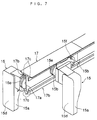
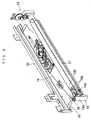
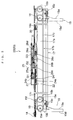
- the article racks 10 are each provided with a pair of right and left pushers 15, 15 for each pushing forward the articles S in a corresponding one of the article passages 11 to dispense the same for vending, and a guide rail 17 for guiding the pushers 15, 15 along opposite side faces thereof, respectively.
- the guide rail 17 is mounted at a central portion of the underside of a corresponding upper shelf 16 immediately above the present shelf 16 in a manner extending in a front-rear direction and at the same time protruding downward. Accordingly, the guide rail 17 also serves as a partition wall for separating upper spaces of the respective article passage 11, 11 from each other.
- the guide rail 17 is comprised of a body plate 17a extending vertically, and a pair of right and left guide portions 17b, 17b integrally formed with the body plate 17a at opposite side faces of the body plate 17a, respectively.
- Each guide portion 17b is comprised of a pair of upper and lower guide protrusions 17c, 17c formed such that the upper guide protrusion 17c protrudes downward from a horizontal portion extending laterally from a top of the body plate 17a, and that the lower guide protrusion 17c extends laterally and obliquely from a bottom of the body plate 17c and then protrudes upward in a manner opposed to the upper guide protrusion 17c.
- the guide rail 17 is formed e.g. by an extrusion molded article of aluminum which is subjected to surface treatment by using alumite.
- the pushers 15 are each comprised of a pusher body 15a inserted into a corresponding one of the article passages 11, for urging the articles S forward along the corresponding article passage 11, a pair of front and rear rollers 15b, 15b mounted on an upper side face of the pusher body 15a, and an auxiliary roller 15c mounted on a lower side face of the same.
- the pusher body 15a is in the form of a block made of a synthetic resin (e.g. polypropylene) and having a front surface serving as a flat urging face 15d for urging articles S forward.
- the rollers 15b are each equipped with a bearing, not shown, and mounted on the upper side face of the pusher body 15a such that each of them is capable of rolling about its horizontal axis.
- Each of the rollers 15b has a peripheral surface formed with a U-shaped groove 15e, and is mounted in the guide rail 17 in a state of the U-shaped groove 15e being fitted on the upper and lower guide protrusions 17c, 17c of the guide rail 17. This construction enables the respective rollers 15b to roll along the guide rail 17 with extremely small frictional resistance to move the pusher 15 forward and backward smoothly.
- the U-shaped groove 15e is formed such that the distance between two bottom points thereof diametrically opposite to each other is e.g. 19.5 mm, while the distance between the upper and lower guide protrusions 17c, 17c is set to e.g. 20.0 mm, i.e. a value slightly larger than that between the two diametrically opposite bottom points of the U-shaped groove 15e.
- This dimensional relationship between the U-shaped groove 15e and the upper and lower guide protrusions 17c, 17c makes it possible to prevent the rollers 15b from coming off the guide rail 17.
- the pair of rollers 15b, 15b are arranged such that an imaginary line connecting between their rotational axes is slightly inclined with respect to another imaginary line perpendicular to the urging face 15d of the pusher body 15a, which allows the urging face 15d to become upright when the pusher body 15a tilts due to pressure from the article S in contact therewith, so as to urge the articles S forward in this state.
- the auxiliary roller 15c (see FIG. 8) is mounted on the lower side face of the pusher body 15a such that it is rotatable about its vertical axis and rolls on the lower side face of the body plate 17a of the guide rail 17.
- the auxiliary roller 15c enables the pusher body 15a to maintain perpendicularity of the urging face 15d thereof with respect to a plane in which the guide rail 17 extends, whereby the frictional resistance to the movement of the pusher 15 along the guide rail 17 can be further decreased.
- the pusher 15 is always urged forward by a drive mechanism (urging means) 20, referred to hereinafter, and held in engagement with the guide rail 17 when it moves to its extreme forward position.
- the stopper plate drive mechanism 13 drives the drive shaft 9a for rotation through a predetermined angle, whereby the stopper plate 9 slides in one direction to release one of the rack opening/closing plates 12 on an opposite side to the direction of the movement of the stopper plate 9.
- the released rack opening/closing plate 12 is pivotally moved to its open position by the urging force of the spring, whereby the dispensing opening 11a of the article passage 11 is opened for dispensing an article S from the article passage 11.
- an article S immediately behind the dispensed article S is blocked by the blocking plate 14 from being dispensed from the article passage 11.
- the pusher 15 moves backward along the guide rail 17 in a state of its pusher body 15a being pushed by the articles S, while during a vending operation, it moves forward along the guide rail 17 in a state of its pusher body 15a pushing the articles S.
- the front and rear rollers 15b, 15b attached to the pusher body 15a roll on the guide rail 17, and further, the rollers 15b are each equipped with the bearing for preventing direct torque transmission between the roller 15b and its rotational shaft, so that moment on the pusher body 15a produced by the urging force acting between the articles S and the pusher body 15a is absorbed by the rollers 15b, 15b, whereby frictional resistance to the movement of the pusher 15 can be far more reduced compared with the conventional construction of the article storage device.
- the auxiliary roller 15c rolling on the side face of the body plate 17a of the guide rail 17 enables the pusher body 15a to maintain perpendicularity of the urging face 15d thereof with respect to a plane in which the guide rail 17 extends, that the guide rail 17 can be produced to close dimensional tolerances by using an extrusion molded article, and that the guide rail 17 is improved in smoothness of guide surfaces thereof by surface treatment by using alumite all contribute to further decreasing the frictional resistance to the movement of the pusher 15 to near zero.
- the urging force of the drive mechanism required for moving the pusher 15 forward can also be reduced, which enhances ease of handling of the article rack 11 when replenishment of vendible articles is carried out.
- rollers 15b, 15b are mounted on the guide rail 17 such that they are rotatable about their respective horizontal axes with the U-shaped grooves thereof being engaged with the upper and lower guide protrusions 17c, 17c, it is possible to construct the guide rail 17 such that it has a smaller width (dimension in a side-to-side direction of the vending machine), compared with a case in which the whole of each roller 15 is received in the guide rail 17.
- the guide rail 17 also serves as a partition wall for separating the upper spaces of the article passage 11, 11 from each other, so that the guide rail 17 having a reduced width allows larger space to be used for storing articles S.
- the drive mechanism 20 for urging a corresponding pusher 15 will be described in detail with reference to FIGS. 8 to 12.
- the drive mechanism 20 is provided for each pusher 15 (see FIG. 11 etc.) and received between an upper case plate 21 and a lower case plate 22 which protrude from the respective top side and bottom side surfaces of a corresponding one of the shelves 16 (see FIGS. 8 and 9).
- These case plates 21, 22 are each constructed to have a small protrusion dimension, i.e. form a container having a small thickness or height.
- the drive mechanism 20 is connected to the pusher 15 by a wire 19.
- the wire 19 is passed over a small pulley 18 arranged at a front end of the bottom side surface of the shelf 16 and then connected to a hook 15f formed on the top of the pusher 15.
- the drive mechanism 20 includes a reduction mechanism 23 comprised of a pulley gear 24, an intermediate gear 25, and a drum gear 26, which mesh with one another.
- the gears 24, 25 and 26 are rotatably supported on respective axes G1, G2 and G3 extending through the upper and lower case plates 21, 22.
- the pulley gear 24 is comprised of a pulley 24a over which the wire 19 is passed and a gear 24b formed integrally on the upper side of the pulley 24a.
- the intermediate gear 25 is comprised of a large gear 25a in mesh with the gear 24b and a small gear 25b integrally formed with the large gear 25a.
- the small gear 25b of the intermediate gear 25 meshes with a gear 26a of the drum gear 26.
- a cylindrical drum 26b is formed integrally on the lower side of the gear 26b.
- helical tension springs 30, 30 On the underside of the drum gear 26, there are formed two projections 26c, 26c, which are each engaged with one end portion of a corresponding one of two helical tension springs 30, 30.
- the helical tension springs 30, 30, which have an identical spring constant, are arranged in parallel with each other, and the other end portions thereof are connected respectively to hooks 16a, 16a (only one of which is shown in FIG. 9) projecting downward from the underside of the shelf 16.
- the drive mechanism 20 makes it possible to secure a longer range of travel of the pusher 15 with respect to a limited length of expansion of each of the helical tension springs 30 through the combination of the helical tension springs 30 and the reduction mechanism 23.
- the urging force of the helical tension springs 30, i.e. an urging load on the pusher 15 is maximized when the pusher 15 is at its extreme backward position, and minimized when the pusher 15 is at its extreme forward position.
- the two helical tension springs 30, 30 connected to the gear 26a of the drum gear 26 in a manner point-symmetrical and parallel with each other transmit torque to the drum gear 26 in a dynamically well-balanced fashion, thereby enabling the pusher 15 to be urged smoothly.
- Reference numeral 27 appearing in FIGS. 10A to 12 indicates a sold-out switch for detecting a sold-out state of articles S in a corresponding one of the article passages 11. This switch 27 is turned on by a projection 26d formed on the drum gear 26 when the pusher 15 moves to its extreme forward position.
- each article rack is formed with a pair of right and left article passages, and two pushers each provided for one of the article passages are guided along an identical guide rail, this is not limitative, but the invention may be applied to an article rack having a single article passage formed therein.
Landscapes
- Physics & Mathematics (AREA)
- General Physics & Mathematics (AREA)
- Vending Machines For Individual Products (AREA)
Claims (5)
- Dispositif de stockage d'articles (1) pour une machine à distribuer, incluant une étagère d'articles disposée à l'intérieur d'un coffret de ladite machine à distribuer (2) d'une manière telle que ladite étagère d'articles peut être déplacée dans une direction avant-arrière et extraite et sortie vers l'avant en dehors dudit coffret de ladite machine à distribuer (2), ladite étagère d'articles (10) ayant un passage d'articles (11) formé dans celle-ci pour recevoir un nombre important d'articles (5) l'un derrière l'autre, un moyen d'ouverture/fermeture d'étagère disposé à une extrémité avant de ladite étagère d'articles, pour ouvrir une ouverture de distribution dudit passage d'articles pendant une opération de distribution, et fermant ladite ouverture de distribution sauf pendant l'opération de distribution, un pousseur (15) inséré dans ledit passage d'articles, pour pousser vers l'avant lesdits articles reçus dans ledit passage d'articles, un élément de guidage (17) disposé au-dessus de ladite étagère d'articles d'une manière telle que ledit élément de guidage s'étend dans ladite direction avant-arrière, pour guider ledit pousseur dans ladite direction avant-arrière, et un moyen de poussée. (30) pour pousser ledit pousseur vers l'avant,
le dispositif de stockage d'articles étant caractérisé en ce que :ledit élément de guidage comprend une plaque de coffret (17a) s'étendant verticalement, et une partie de guidage formée solidairement avec ladite plaque de coffret, ladite partie de guidage ayant une paire de saillies de guidage (17c) espacées latéralement de ladite plaque de coffret et étant verticalement opposées l'une à l'autre, etledit pousseur comprend un corps de pousseur inséré dans ledit passage d'articles et une paire de rouleaux avant et arrière (15b) formé chacun avec une rainure (15e) en forme de U et fixé à une face supérieure dudit corps de pousseur de manière à pouvoir tourner autour des axes horizontaux respectifs, ledit pousseur étant monté entre lesdites saillies de guidage verticalement opposées de ladite partie de guidage dudit élément de guidage, avec ladite rainure (15e) en forme de U de chacun desdits rouleaux étant ajustée sur lesdites saillies de guidage verticalement opposées. - Dispositif de stockage d'articles selon la revendication 1, dans lequel chacun desdits rouleaux (15b) est muni d'un palier.
- Dispositif de stockage d'articles selon la revendication 1 ou 2, dans lequel ledit pousseur (15) comprend, en outre, un rouleau auxiliaire (15c) monté sur ledit corps de pousseur à un emplacement au-dessous desdits rouleaux, pour rotation autour d'un axe vertical dudit rouleau auxiliaire pour rouler sur une face latérale de ladite plaque de coffret dudit élément de guidage.
- Dispositif de stockage d'articles selon l'une quelconque des revendications 1, 2 ou 3, dans lequel ledit élément de guidage est constitué d'un article moulé par extrusion d'aluminium.
- Dispositif de stockage d'articles selon la revendication 4, dans lequel ledit élément de guidage est soumis à un traitement en surface en utilisant de l'alumite.
Priority Applications (2)
| Application Number | Priority Date | Filing Date | Title |
|---|---|---|---|
| DE1998607342 DE69807342T2 (de) | 1998-11-30 | 1998-11-30 | Warenspeicher-Modul für Verkaufsautomaten |
| EP19980122713 EP1006494B1 (fr) | 1998-11-30 | 1998-11-30 | Module de stockage d'articles pour distributeur automatique |
Applications Claiming Priority (1)
| Application Number | Priority Date | Filing Date | Title |
|---|---|---|---|
| EP19980122713 EP1006494B1 (fr) | 1998-11-30 | 1998-11-30 | Module de stockage d'articles pour distributeur automatique |
Publications (2)
| Publication Number | Publication Date |
|---|---|
| EP1006494A1 EP1006494A1 (fr) | 2000-06-07 |
| EP1006494B1 true EP1006494B1 (fr) | 2002-08-21 |
Family
ID=8233056
Family Applications (1)
| Application Number | Title | Priority Date | Filing Date |
|---|---|---|---|
| EP19980122713 Expired - Lifetime EP1006494B1 (fr) | 1998-11-30 | 1998-11-30 | Module de stockage d'articles pour distributeur automatique |
Country Status (2)
| Country | Link |
|---|---|
| EP (1) | EP1006494B1 (fr) |
| DE (1) | DE69807342T2 (fr) |
Cited By (1)
| Publication number | Priority date | Publication date | Assignee | Title |
|---|---|---|---|---|
| RU2571408C2 (ru) * | 2011-04-26 | 2015-12-20 | Хофемар С.А. | Торговый автомат |
Families Citing this family (1)
| Publication number | Priority date | Publication date | Assignee | Title |
|---|---|---|---|---|
| CN116853793B (zh) * | 2022-12-06 | 2026-05-15 | 张晴 | 一种扫码入库的生物样本分装车及方法 |
Family Cites Families (8)
| Publication number | Priority date | Publication date | Assignee | Title |
|---|---|---|---|---|
| US2893596A (en) * | 1953-03-04 | 1959-07-07 | Rowe Mfg Co Inc | Sandwich merchandising machine |
| US3282466A (en) * | 1964-09-11 | 1966-11-01 | Seeburg Corp | Magazine structures for vending machines |
| US4200201A (en) * | 1977-01-24 | 1980-04-29 | Rod Pierce and Associates | Machine having module with carriage for advancing row of articles |
| GB8907812D0 (en) * | 1989-04-06 | 1989-05-17 | Advanced Vending Services | Vending machine |
| JP3245539B2 (ja) * | 1996-11-22 | 2002-01-15 | 松下冷機株式会社 | 自動販売機の商品収納装置 |
| JPH10188107A (ja) * | 1996-12-20 | 1998-07-21 | Sanyo Electric Co Ltd | 自動販売機の商品収納装置 |
| JP3508903B2 (ja) * | 1997-03-06 | 2004-03-22 | 富士電機リテイルシステムズ株式会社 | 自動販売機の商品収納装置 |
| JP3471554B2 (ja) * | 1997-03-11 | 2003-12-02 | 松下冷機株式会社 | 自動販売機の商品収納装置 |
-
1998
- 1998-11-30 EP EP19980122713 patent/EP1006494B1/fr not_active Expired - Lifetime
- 1998-11-30 DE DE1998607342 patent/DE69807342T2/de not_active Expired - Fee Related
Cited By (1)
| Publication number | Priority date | Publication date | Assignee | Title |
|---|---|---|---|---|
| RU2571408C2 (ru) * | 2011-04-26 | 2015-12-20 | Хофемар С.А. | Торговый автомат |
Also Published As
| Publication number | Publication date |
|---|---|
| EP1006494A1 (fr) | 2000-06-07 |
| DE69807342T2 (de) | 2003-04-24 |
| DE69807342D1 (de) | 2002-09-26 |
Similar Documents
| Publication | Publication Date | Title |
|---|---|---|
| US5873489A (en) | Commodities storing apparatus of vending machine | |
| US6253954B1 (en) | Article storage/dispensing device for vending machine | |
| US6241121B1 (en) | Commodity accommodating unit of an automatic vending machine | |
| JP3524818B2 (ja) | 自動販売機の商品収納装置および商品収納方法 | |
| CN107195099B (zh) | 自动售货机的商品送出装置 | |
| JP2002150397A (ja) | 自動販売機の商品収納払出し装置 | |
| JP3524780B2 (ja) | 自動販売機の商品搬出装置 | |
| KR101645691B1 (ko) | 자판기 | |
| EP1006494A1 (fr) | Module de stockage d'articles pour distributeur automatique | |
| CN112530084B (zh) | 自动售货机和补货方法 | |
| JP3478064B2 (ja) | 自動販売機の商品収納装置 | |
| JP2004005184A (ja) | 自動販売機の商品収納払出し装置 | |
| JP3811577B2 (ja) | 自動販売機の商品投出装置 | |
| JP3800733B2 (ja) | 自動販売機の商品収納装置 | |
| JP3403089B2 (ja) | 自動販売機の商品収納払出装置 | |
| EP1006495B1 (fr) | Appareil de stockage d'articles pour distributeur automatique | |
| JP4253949B2 (ja) | 自動販売機の商品搬出装置 | |
| JP3508903B2 (ja) | 自動販売機の商品収納装置 | |
| JP3511194B2 (ja) | 自動販売機の商品搬出装置 | |
| JP3670862B2 (ja) | 自動販売機の商品収納払出装置 | |
| JP4289780B2 (ja) | 自動販売機の商品収納払出し装置 | |
| JP3478065B2 (ja) | 自動販売機の商品収納装置 | |
| JP3019930B1 (ja) | 自動販売機の商品収納装置 | |
| JP3478066B2 (ja) | 自動販売機の商品収納装置 | |
| JP2000123242A (ja) | 自動販売機の商品搬出装置 |
Legal Events
| Date | Code | Title | Description |
|---|---|---|---|
| PUAI | Public reference made under article 153(3) epc to a published international application that has entered the european phase |
Free format text: ORIGINAL CODE: 0009012 |
|
| AK | Designated contracting states |
Kind code of ref document: A1 Designated state(s): DE FR GB IT |
|
| AX | Request for extension of the european patent |
Free format text: AL;LT;LV;MK;RO;SI |
|
| 17P | Request for examination filed |
Effective date: 20000717 |
|
| AKX | Designation fees paid |
Free format text: DE FR GB IT |
|
| GRAG | Despatch of communication of intention to grant |
Free format text: ORIGINAL CODE: EPIDOS AGRA |
|
| 17Q | First examination report despatched |
Effective date: 20011203 |
|
| GRAG | Despatch of communication of intention to grant |
Free format text: ORIGINAL CODE: EPIDOS AGRA |
|
| GRAH | Despatch of communication of intention to grant a patent |
Free format text: ORIGINAL CODE: EPIDOS IGRA |
|
| GRAH | Despatch of communication of intention to grant a patent |
Free format text: ORIGINAL CODE: EPIDOS IGRA |
|
| GRAA | (expected) grant |
Free format text: ORIGINAL CODE: 0009210 |
|
| AK | Designated contracting states |
Kind code of ref document: B1 Designated state(s): DE FR GB IT |
|
| REG | Reference to a national code |
Ref country code: GB Ref legal event code: FG4D |
|
| REF | Corresponds to: |
Ref document number: 69807342 Country of ref document: DE Date of ref document: 20020926 |
|
| RAP2 | Party data changed (patent owner data changed or rights of a patent transferred) |
Owner name: FUJI ELECTRIC CO., LTD. |
|
| REG | Reference to a national code |
Ref country code: GB Ref legal event code: 732E |
|
| ET | Fr: translation filed | ||
| PLBE | No opposition filed within time limit |
Free format text: ORIGINAL CODE: 0009261 |
|
| STAA | Information on the status of an ep patent application or granted ep patent |
Free format text: STATUS: NO OPPOSITION FILED WITHIN TIME LIMIT |
|
| REG | Reference to a national code |
Ref country code: FR Ref legal event code: TP |
|
| 26N | No opposition filed |
Effective date: 20030522 |
|
| PGFP | Annual fee paid to national office [announced via postgrant information from national office to epo] |
Ref country code: FR Payment date: 20061108 Year of fee payment: 9 |
|
| PGFP | Annual fee paid to national office [announced via postgrant information from national office to epo] |
Ref country code: DE Payment date: 20061123 Year of fee payment: 9 |
|
| PGFP | Annual fee paid to national office [announced via postgrant information from national office to epo] |
Ref country code: GB Payment date: 20061129 Year of fee payment: 9 |
|
| PGFP | Annual fee paid to national office [announced via postgrant information from national office to epo] |
Ref country code: IT Payment date: 20061130 Year of fee payment: 9 |
|
| GBPC | Gb: european patent ceased through non-payment of renewal fee |
Effective date: 20071130 |
|
| PG25 | Lapsed in a contracting state [announced via postgrant information from national office to epo] |
Ref country code: DE Free format text: LAPSE BECAUSE OF NON-PAYMENT OF DUE FEES Effective date: 20080603 |
|
| REG | Reference to a national code |
Ref country code: FR Ref legal event code: ST Effective date: 20080930 |
|
| PG25 | Lapsed in a contracting state [announced via postgrant information from national office to epo] |
Ref country code: GB Free format text: LAPSE BECAUSE OF NON-PAYMENT OF DUE FEES Effective date: 20071130 |
|
| PG25 | Lapsed in a contracting state [announced via postgrant information from national office to epo] |
Ref country code: FR Free format text: LAPSE BECAUSE OF NON-PAYMENT OF DUE FEES Effective date: 20071130 |
|
| PG25 | Lapsed in a contracting state [announced via postgrant information from national office to epo] |
Ref country code: IT Free format text: LAPSE BECAUSE OF NON-PAYMENT OF DUE FEES Effective date: 20071130 |