EP1006533A1 - Cuve d'un réacteur nucléaire à eau sous pression comportant un dispositif de tranquillisation de la circulation d'eau de refroidissement en fond de cuve - Google Patents
Cuve d'un réacteur nucléaire à eau sous pression comportant un dispositif de tranquillisation de la circulation d'eau de refroidissement en fond de cuve Download PDFInfo
- Publication number
- EP1006533A1 EP1006533A1 EP99402824A EP99402824A EP1006533A1 EP 1006533 A1 EP1006533 A1 EP 1006533A1 EP 99402824 A EP99402824 A EP 99402824A EP 99402824 A EP99402824 A EP 99402824A EP 1006533 A1 EP1006533 A1 EP 1006533A1
- Authority
- EP
- European Patent Office
- Prior art keywords
- cylindrical wall
- nuclear reactor
- tank
- support plate
- core
- Prior art date
- Legal status (The legal status is an assumption and is not a legal conclusion. Google has not performed a legal analysis and makes no representation as to the accuracy of the status listed.)
- Granted
Links
- 239000000498 cooling water Substances 0.000 title claims abstract description 28
- XLYOFNOQVPJJNP-UHFFFAOYSA-N water Substances O XLYOFNOQVPJJNP-UHFFFAOYSA-N 0.000 title claims description 17
- 239000000725 suspension Substances 0.000 claims description 12
- 230000002787 reinforcement Effects 0.000 claims description 8
- 238000001816 cooling Methods 0.000 claims description 6
- 230000003014 reinforcing effect Effects 0.000 claims description 6
- 230000002093 peripheral effect Effects 0.000 claims description 5
- 239000007787 solid Substances 0.000 claims description 2
- 230000002936 tranquilizing effect Effects 0.000 abstract description 7
- 230000000712 assembly Effects 0.000 description 9
- 238000000429 assembly Methods 0.000 description 9
- 239000000446 fuel Substances 0.000 description 5
- 239000003204 tranquilizing agent Substances 0.000 description 5
- 210000005069 ears Anatomy 0.000 description 4
- 229940125725 tranquilizer Drugs 0.000 description 4
- 239000011324 bead Substances 0.000 description 2
- 239000012530 fluid Substances 0.000 description 2
- 229910001220 stainless steel Inorganic materials 0.000 description 2
- 239000010935 stainless steel Substances 0.000 description 2
- 238000003466 welding Methods 0.000 description 2
- 229910000831 Steel Inorganic materials 0.000 description 1
- 230000000694 effects Effects 0.000 description 1
- 230000007613 environmental effect Effects 0.000 description 1
- 238000000265 homogenisation Methods 0.000 description 1
- 238000007689 inspection Methods 0.000 description 1
- 238000012423 maintenance Methods 0.000 description 1
- 239000007769 metal material Substances 0.000 description 1
- 230000000284 resting effect Effects 0.000 description 1
- 238000000638 solvent extraction Methods 0.000 description 1
- 239000010959 steel Substances 0.000 description 1
Images


Classifications
-
- G—PHYSICS
- G21—NUCLEAR PHYSICS; NUCLEAR ENGINEERING
- G21C—NUCLEAR REACTORS
- G21C13/00—Pressure vessels; Containment vessels; Containment in general
- G21C13/02—Details
-
- Y—GENERAL TAGGING OF NEW TECHNOLOGICAL DEVELOPMENTS; GENERAL TAGGING OF CROSS-SECTIONAL TECHNOLOGIES SPANNING OVER SEVERAL SECTIONS OF THE IPC; TECHNICAL SUBJECTS COVERED BY FORMER USPC CROSS-REFERENCE ART COLLECTIONS [XRACs] AND DIGESTS
- Y02—TECHNOLOGIES OR APPLICATIONS FOR MITIGATION OR ADAPTATION AGAINST CLIMATE CHANGE
- Y02E—REDUCTION OF GREENHOUSE GAS [GHG] EMISSIONS, RELATED TO ENERGY GENERATION, TRANSMISSION OR DISTRIBUTION
- Y02E30/00—Energy generation of nuclear origin
- Y02E30/30—Nuclear fission reactors
Definitions
- the invention relates to a tank of a nuclear water reactor under pressure comprising a device for tranquilizing the circulation of water in the bottom of the tank.
- Pressurized water nuclear reactors generally include a generally cylindrical tank arranged in service with its vertical axis, and closed at its lower part by a domed bottom of form generally hemispherical.
- the tank in which the heart of the nuclear reactor consisting of fuel assemblies, includes a set of internal equipment, called lower internal equipment, intended to support and maintain the assemblies of the nuclear reactor core.
- These lower internal equipments include in particular a very thick plate, arranged horizontally above from the curved bottom of the tank. Between the heart support plate and the domed bottom of the tank is delimited a tank bottom space generally having a hemispherical shape.
- At the periphery of the background space of tank opens, by its lower end, a defined annular space by the internal surface of the tank and a cylindrical core envelope coaxial with the tank.
- the cooling water from the reactor core is distributed in the annular space at its upper part, flows from top to bottom, then enters in the tank bottom space, at the peripheral part of this space. Inside the tank bottom space, the cooling water flow undergoes a 180 ° change of direction, the cooling water being caused to enter the heart by passage through through openings of the core support plate and to circulate inside the assemblies from the heart in the vertical direction and from bottom to top.
- Uneven distribution of cooling water in the different parts of the nuclear reactor core and flow variations over time can cause uneven cooling of the heart with risk of the appearance of hotter zones inside the core, and also cause hydraulic stresses on the assemblies combustibles.
- devices consisting of plates have been proposed openings which are fixed via columns in arrangements horizontal parallel to the core support plate, below the heart support plate. Such devices make it possible to attenuate the intensity of the vortices which tend to form on the flow cooling water, at the bottom of the tank.
- the object of the invention is to provide a vessel for a nuclear reactor pressurized water, of generally cylindrical shape, arranged in service, with its vertical axis and closed at its lower end by a curved bottom, comprising, above the curved bottom, a core support plate of the reactor, in a horizontal arrangement, delimiting with the convex bottom a tank bottom space and means for directing an annular flow pressurized cooling water from top to bottom at the periphery of the tank bottom space, as well as a flow tranquilization device cooling water suspended below the support plate of the core, to calm and homogenize the flow of cooling water in the tank bottom space, before the cooling water enters the reactor core through openings through the plate heart support, the tranquilization device not only allowing to calm and homogenize the flow of cooling water but still to channel this cooling water to the inlet of the heart, the device which can also be easily mounted on equipment lower internals of the nuclear reactor, without limiting the dismantling possibilities, handling and maintenance of lower internal equipment, and tank bottom inspection.
- the tranquilization device comprises at least one cylindrical wall having an axis parallel to the axis of the tank and extending over a height between 15 and 40% of the maximum height, in the direction axial, from the tank bottom space.
- Figure 1 is an axial sectional view of the lower part of the tank of a pressurized water nuclear reactor comprising a device for tranquillization according to the invention.
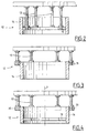
- Figures 2, 3 and 4 are views in axial section of devices for tranquilization of a reactor vessel according to the invention and according to three variants of achievement.
- Figure 5 is a top view of a still device according to the invention.
- FIG. 6 is a view in axial section along 6-6 of FIG. 5.
- the tank 1 comprises a cylindrical envelope 1a constituted by very thick ferrules welded end to end and a domed bottom hemispherical 1b attached and welded to the lower part of the cylindrical envelope 1a.
- the tank 1 contains the lower internal equipment 2 of the reactor nuclear which include in particular a core envelope 3 of shape cylindrical which is arranged coaxially inside the tank 1 whose axis 4 is vertical and a very thick core support plate 5.
- the plaque of core support 5 is welded to the lower end of the casing of heart 3 which ensures the suspension of the heart support plate at inside the tank.
- the core support plate 5 is immobilized inside the tank by shims 6 distributed around the axis 4 of the tank and having parts welded to the inner wall of the tank, the lower end of the cylindrical casing 1a, above the curved bottom 1b.
- the core 8 of the nuclear reactor consists of assemblies of juxtaposed prismatic fuel, resting on their part lower end on the upper surface of the support plate heart 5.
- the fuel assemblies constituting the core 8 of the reactor nuclear are kept inside the core envelope 3, by a partitioning 7.
- the core support plate 5 and the curved bottom 1b delimit between them a hemispherical tank bottom space 10.
- annular space 9 communicating with its lower part, at the level of the core support plate 5, with tank bottom space 10.
- Nuclear reactor cooling water is introduced into the upper part of the annular space 9 (not shown in FIG. 1), so that the cooling water circulates in the form of an annular flow, from top to bottom, in space 9, then enters bottom space tank 10, in its peripheral upper part.
- the direction of circulation of the cooling water flow changes, so that the water flow of cooling enters the reactor core 8 through numerous openings 11 crossing the core support plate and allowing distribution the flow of cooling water throughout the surface of the heart.
- the core support plate 5 is crossed by at least one opening (usually four) below each of the fuel assemblies from reactor core 8.
- a stilling device 12 comprising a cylindrical envelope or ferrule 14 suspended by columns 13 under the support plate core 5.
- the ferrule 14 is placed in a coaxial arrangement with respect to the vessel 1 of the reactor and has a diameter and a height in the direction axial as it extends over a substantial part of the space of tank bottom 10.
- the desired dimensions of the ferrule 14 were determined to obtain satisfactory tranquilization and homogenization of the flow of water in the bottom of the tank.
- the ferrule 14 must have a diameter at less than 30% and at most 60% of the inner diameter of the tank. In the case of a nuclear reactor vessel whose internal diameter is about 4 m, the diameter of the ferrule 14 of the stilling device 12 must therefore be at least equal to 1.20 m and at most equal to 2.40 m.
- the height of the shell 14 must be at least equal to 15% and at most equal to 40% of the maximum height in the axial direction 4 of the space 10, i.e. of the height h indicated in figure 1. In the case of a nuclear reactor of usual dimensions, this height h is close to 2 m, so that the height of the ferrule 14 of the stilling device 12 must be at least equal to 0.30 m and at most equal to 0.80 m.
- the distance from the bottom surface of the support plate core 5 and the upper edge of the ferrule 14 must be between 10 and 35% of the distance h, i.e., in the case of a tank where the distance h is close 2 m, between 0.20 and 0.70 m.
- the tranquilizer 12 may have a reinforcing ring 15 fixed on the surface internal of the cylindrical shell 14, along its entire internal periphery.
- the columns 13 are fixed at their upper part, by a fixing plate, under the heart support plate 5 and at their lower part on the ring reinforcement 15 of the stilling device 12.
- a plate can be used circular hollow, crossed by circular or non-circular openings, fixed by its outer peripheral edge, on the inner surface of the cylindrical shell 14.
- the plate or the reinforcement 15, which is fixed by welding to the internal surface of the shell 14, includes, in arrangements distributed over a median circle of the ring or at the periphery of the plate, openings 17 (for example four) allowing the attachment of the stilling device 12 to the ends lower of the suspension columns 13.
- the openings 17 can consist of smooth holes inside which we engage a end part of the columns 13 which can be fixed on the reinforcing ring 15 by a weld bead.
- Figures 3 and 4 show two alternative embodiments of the stilling device 12.
- the corresponding elements in the figures 3 and 4 on the one hand and 1, 2, 5 and 6 on the other hand have the same references.
- the cylindrical shell 14 is reinforced by an outer ring 18 on which the ends are fixed lower columns 13 ensuring the suspension of the stilling device 12.
- the shell 14 is integral with an internal reinforcement ring 19, similar to the reinforcement ring 15 of the embodiment shown in the figures 1, 2, 5 and 6.
- suspension lugs or ears 20 are fixed to the outer surface of the shell 14, in its upper part, so as to be find radially projecting from the outer surface of the ferrule 14.
- Des columns 13 are each fixed at their lower end to one ear suspension 20 which is crossed by an opening for receiving the end part of the column 13.
- suspension ears distributed around the periphery of the ferrule 14, in positions deducted from each other by a rotation 60 ° around axis 4 common to the nuclear reactor vessel and the shell 14 of the stilling device 12.
- provision can be made only three, four or five suspension ears or, more than six ears suspension; in this case, the suspension is ensured by a corresponding number of columns 13.
- the suspension can be achieved via of a number of columns 13 other than four or six, the openings of fixing of the end parts of the columns being provided in the rings reinforcement 15 or 18.
- the stilling device 12 comprising the cylindrical wall 14 which is suspended under the core support plate 5, so as to occupy part of the tank bottom space 10, provides tranquilization of the flow of cooling water entering through the peripheral upper part tank bottom space 10 and uniformity of the flow, so that the field of pressures and flows at the inlet of the reactor core 8 is substantially uniform along the entire cross section of the heart.
- the cylindrical shell 14 of the device tranquilization 12 cancels or reduces the intensity of swirls on the cooling water circulation in the bottom space tank 10. It is also possible to confine intensity vortices reduced still present in the cooling water flow at inside the cylindrical wall 14 of the stilling device 12.
- the stilling device 12 is of a simple structure and can be easily designed, produced and installed under the core support plate lower internal equipment of the nuclear reactor.
- the tranquilizer has no means fixing on the tank but is completely suspended from the equipment lower internal, there is no intervention on the wall of the tank to set up the device according to the invention.
- the stilling device which is transported with the lower internal equipment, can be easily controlled in the pool of the reactor, during unloading of lower internal equipment.
- the tranquilization device can consist of any straight cylindrical or prismatic ferrule whatever the shape of its cross section, that is to say by any wall whose generators are all parallel to each other and parallel to the axis of the wall and whose cross section perpendicular to the axis and generators have the shape of a closed contour which can be different of a circular outline.
- the cross section of the wall of the tranquilizer may have an elliptical or polygonal shape.
- the stilling device of the nuclear reactor vessel may comprise at least two and more generally a plurality of cylindrical walls with parallel axes suspended under the core support plate, in arrangements side by side or in coaxial arrangements.
- the height, in the axial direction of the different cylindrical walls is always understood between 15 and 40% of the maximum height of the tank bottom space.
- the tranquilization device can include at least two joined ferrules or coaxial, arranged inside the tank bottom space, in a cylindrical volume having for axis the axis of the tank and a diameter included between 30 and 60% of the inside diameter of the tank.
- the elements constituting the tranquilization device and in particular the cylindrical envelope can be made of any metallic material able to withstand the environmental conditions prevailing in the bottom of the tank; in particular, the cylindrical shell can be made of weakly steel alloyed, possibly coated with stainless steel, or in stainless steel.
- the invention applies in the case of any nuclear water reactor under pressure comprising a tank in which a support plate for core delimits a tank bottom space receiving an annular flow of water pressure cooling.
Landscapes
- Physics & Mathematics (AREA)
- Engineering & Computer Science (AREA)
- Plasma & Fusion (AREA)
- General Engineering & Computer Science (AREA)
- High Energy & Nuclear Physics (AREA)
- Structure Of Emergency Protection For Nuclear Reactors (AREA)
- Pressure Vessels And Lids Thereof (AREA)
- Other Liquid Machine Or Engine Such As Wave Power Use (AREA)
Abstract
Description
Claims (11)
- Cuve d'un réacteur nucléaire à eau sous pression de forme globalement cylindrique, disposée en service avec son axe (4) vertical, et fermée à son extrémité inférieure par un fond bombé (1b), comportant au-dessus du fond bombé (1b) une plaque de support (5) du coeur (8) du réacteur, dans une disposition horizontale, délimitant avec le fond bombé (1b) un espace de fond de cuve (10) et des moyens pour diriger un flux annulaire d'eau de refroidissement sous pression de haut en bas à la périphérie de l'espace de fond de cuve (10), ainsi qu'un dispositif de tranquillisation (12) du flux d'eau de refroidissement suspendu en-dessous de la plaque (5) de support du coeur (8), pour tranquilliser et homogénéiser l'écoulement d'eau de refroidissement dans l'espace de fond de cuve (10) avant que l'eau de refroidissement ne pénètre dans le coeur (8) du réacteur par des ouvertures (11 ) traversant la plaque de support (5) du coeur (8), caractérisée par le fait que le dispositif de tranquillisation (12) comporte au moins une paroi cylindrique (14) ayant un axe parallèle à l'axe (4) de la cuve et s'étendant sur une hauteur comprise entre 15 et 40 % de la hauteur maximale, dans la direction axiale, de l'espace de fond de cuve (10).
- Cuve de réacteur nucléaire suivant la revendication 1, caractérisée par le fait que le dispositif de tranquillisation (12) comporte une seule paroi cylindrique (14) à section circulaire disposée coaxialement par rapport à la cuve (1) de réacteur nucléaire et ayant un diamètre compris entre 30 et 60 % du diamètre intérieur d'une partie cylindrique (1a) de la cuve (1).
- Cuve de réacteur nucléaire suivant la revendication 2, caractérisée par le fait que la paroi cylindrique (14) comporte une extrémité supérieure située à une distance d'une face inférieure de la plaque de support de coeur (5), dans la direction axiale (4) de la cuve, comprise entre 10 et 35 % de la hauteur maximale (h) de l'espace de fond de cuve (10).
- Cuve de réacteur nucléaire suivant l'une quelconque des revendications 2 et 3, caractérisée par le fait que la paroi cylindrique (14) est une paroi entièrement pleine.
- Cuve de réacteur nucléaire suivant l'une quelconque des revendications 2 et 3, caractérisée par le fait que la paroi cylindrique (14) est traversée par des ouvertures.
- Cuve de réacteur nucléaire suivant l'une quelconque des revendications 1 à 5, caractérisée par le fait que la paroi cylindrique (14) du dispositif de tranquillisation (12) comporte une plaque de renforcement (15) fixé sur une surface de la paroi cylindrique (14) dans une disposition coaxiale à la paroi cylindrique (14) et que la paroi cylindrique (14) du dispositif de tranquillisation (12) est suspendue sous la plaque de support de coeur (5), par l'intermédiaire de colonnes verticales (13) qui sont fixées, à l'une de leurs extrémités ou extrémité supérieure, sur la plaque de support de coeur et, par une seconde extrémité ou extrémité inférieure, sur la plaque de renforcement (15, 18) de la paroi cylindrique (14).
- Cuve de réacteur nucléaire suivant la revendication 6, caractérisée par le fait que la plaque de renforcement (15) de la paroi cylindrique (14) est un anneau fixé sur une surface interne de la paroi cylindrique (14).
- Cuve de réacteur nucléaire suivant la revendication 6, caractérisée par le fait que la plaque de renforcement (15) de la paroi cylindrique (14) est une plaque circulaire traversée par des ouvertures, par exemple circulaires. fixée par son bord périphérique externe sur une surface interne de la paroi cylindrique (14).
- Cuve de réacteur nucléaire suivant la revendication 6, caractérisée par le fait que la plaque de renforcement est un anneau de renforcement (18) fixé sur la surface extérieure de la paroi cylindrique (14), dans une zone voisine d'une extrémité supérieure de la paroi cylindrique (14).
- Cuve de réacteur nucléaire suivant l'une quelconque des revendications 1 à 5, caractérisée par le fait que le dispositif de tranquillisation (12) comporte au moins trois oreilles de suspension (20) fixées sur une surface externe de la paroi cylindrique (14) au voisinage de son extrémité supérieure et que la paroi cylindrique (14) est suspendue sous la plaque de support de coeur (5), par l'intermédiaire d'au moins trois colonnes (13) fixées par une première extrémité, ou extrémité supérieure, sur la plaque de support de coeur (5) et par une seconde extrémité, ou extrémité inférieure, sur une oreille de suspension (20).
- Cuve de réacteur nucléaire suivant la revendication 1, caractérisée par le fait que le dispositif de tranquillisation (12) comporte au moins deux parois cylindriques (14) suspendues sous la plaque de support de coeur (5) dans une des dispositions suivantes : disposition accolée ou disposition coaxiale.
Applications Claiming Priority (2)
| Application Number | Priority Date | Filing Date | Title |
|---|---|---|---|
| FR9815144A FR2786603B1 (fr) | 1998-12-01 | 1998-12-01 | Cuve d'un reacteur nucleaire a eau sous pression comportant un dispositif de tranquillisation de la circulation d'eau de refroidissement en fond de cuve |
| FR9815144 | 1998-12-01 |
Publications (3)
| Publication Number | Publication Date |
|---|---|
| EP1006533A1 true EP1006533A1 (fr) | 2000-06-07 |
| EP1006533B1 EP1006533B1 (fr) | 2006-05-24 |
| EP1006533B8 EP1006533B8 (fr) | 2006-07-19 |
Family
ID=9533429
Family Applications (1)
| Application Number | Title | Priority Date | Filing Date |
|---|---|---|---|
| EP99402824A Expired - Lifetime EP1006533B8 (fr) | 1998-12-01 | 1999-11-15 | Cuve d'un réacteur nucléaire à eau sous pression comportant un dispositif de tranquillisation de la circulation d'eau de refroidissement en fond de cuve |
Country Status (6)
| Country | Link |
|---|---|
| EP (1) | EP1006533B8 (fr) |
| CN (1) | CN100511488C (fr) |
| AT (1) | ATE327558T1 (fr) |
| DE (1) | DE69931455T2 (fr) |
| ES (1) | ES2265679T3 (fr) |
| FR (1) | FR2786603B1 (fr) |
Cited By (4)
| Publication number | Priority date | Publication date | Assignee | Title |
|---|---|---|---|---|
| EP1783780A1 (fr) * | 2005-11-04 | 2007-05-09 | Areva NP | Cuve de réacteur nucléaire à eau sous pression |
| EP1489624A3 (fr) * | 2003-06-18 | 2008-10-08 | Mitsubishi Heavy Industries, Ltd. | Structure interne d'un réacteur nucléaire |
| CN103329211A (zh) * | 2011-01-19 | 2013-09-25 | 株式会社东芝 | 压水反应堆 |
| CN103871502A (zh) * | 2012-12-14 | 2014-06-18 | 中国核动力研究设计院 | 一种核反应堆下腔室筒式流量分配装置 |
Families Citing this family (8)
| Publication number | Priority date | Publication date | Assignee | Title |
|---|---|---|---|---|
| CN103871503B (zh) * | 2012-12-14 | 2016-08-10 | 中国核动力研究设计院 | 一种核反应堆下腔室板状流量分配装置 |
| CN103871501B (zh) * | 2012-12-14 | 2017-05-10 | 中国核动力研究设计院 | 一种核反应堆下腔室流量分配装置 |
| CN103971763A (zh) * | 2014-05-06 | 2014-08-06 | 中广核工程有限公司 | 核电站反应堆的堆内流量分配装置 |
| WO2016005591A1 (fr) | 2014-07-10 | 2016-01-14 | Eurovia | Lait de compose calco-magnésien pour matériau routier bitumineux |
| CN107221368B (zh) * | 2017-07-26 | 2023-07-04 | 中国核动力研究设计院 | 反应堆冷却剂抑涡及流量分配装置及反应堆堆内构件 |
| FR3094365B1 (fr) | 2019-03-26 | 2021-04-09 | Eurovia | Additifs pour matériau bitumineux coulé à froid avec un liant paraffinique à montée en cohésion rapide |
| CN111681786B (zh) * | 2020-06-23 | 2022-12-30 | 中国科学院上海应用物理研究所 | 一种反应堆容器的下腔室结构及反应堆容器 |
| FR3133202B1 (fr) | 2022-03-02 | 2026-01-02 | Eurovia | Procédé de fabrication d’enrobés hydrocarbonés à froid et enrobés hydrocarbonés à froid à montée en cohésion rapide |
Citations (4)
| Publication number | Priority date | Publication date | Assignee | Title |
|---|---|---|---|---|
| GB1252519A (fr) * | 1969-10-07 | 1971-11-03 | ||
| EP0238390A1 (fr) * | 1986-03-07 | 1987-09-23 | Framatome | Equipements internes de réacteurs nucleaires à cuve allongée |
| US4696792A (en) * | 1984-07-30 | 1987-09-29 | General Electric Company | Nuclear reactor coolant recirculation |
| EP0328447A1 (fr) * | 1988-02-11 | 1989-08-16 | Framatome | Equipements internes inférieurs de réacteur nucléaire |
Family Cites Families (1)
| Publication number | Priority date | Publication date | Assignee | Title |
|---|---|---|---|---|
| FR2717608B1 (fr) * | 1994-03-15 | 1996-06-14 | Framatome Sa | Cuve d'un réacteur nucléaire comportant des moyens de maintien de ses équipements internes inférieurs et procédé d'ajustage des moyens de maintien. |
-
1998
- 1998-12-01 FR FR9815144A patent/FR2786603B1/fr not_active Expired - Fee Related
-
1999
- 1999-11-15 DE DE69931455T patent/DE69931455T2/de not_active Expired - Lifetime
- 1999-11-15 AT AT99402824T patent/ATE327558T1/de not_active IP Right Cessation
- 1999-11-15 EP EP99402824A patent/EP1006533B8/fr not_active Expired - Lifetime
- 1999-11-15 ES ES99402824T patent/ES2265679T3/es not_active Expired - Lifetime
- 1999-11-30 CN CNB991228146A patent/CN100511488C/zh not_active Expired - Fee Related
Patent Citations (4)
| Publication number | Priority date | Publication date | Assignee | Title |
|---|---|---|---|---|
| GB1252519A (fr) * | 1969-10-07 | 1971-11-03 | ||
| US4696792A (en) * | 1984-07-30 | 1987-09-29 | General Electric Company | Nuclear reactor coolant recirculation |
| EP0238390A1 (fr) * | 1986-03-07 | 1987-09-23 | Framatome | Equipements internes de réacteurs nucleaires à cuve allongée |
| EP0328447A1 (fr) * | 1988-02-11 | 1989-08-16 | Framatome | Equipements internes inférieurs de réacteur nucléaire |
Cited By (8)
| Publication number | Priority date | Publication date | Assignee | Title |
|---|---|---|---|---|
| EP1489624A3 (fr) * | 2003-06-18 | 2008-10-08 | Mitsubishi Heavy Industries, Ltd. | Structure interne d'un réacteur nucléaire |
| EP1783780A1 (fr) * | 2005-11-04 | 2007-05-09 | Areva NP | Cuve de réacteur nucléaire à eau sous pression |
| FR2893176A1 (fr) * | 2005-11-04 | 2007-05-11 | Framatome Anp Sas | Cuve de reacteur nucleaire a eau sous pression. |
| JP2007163477A (ja) * | 2005-11-04 | 2007-06-28 | Areva Np | 加圧水型原子炉容器 |
| US7929657B2 (en) | 2005-11-04 | 2011-04-19 | Areva Np | Pressurised water nuclear reactor vessel |
| KR101299067B1 (ko) * | 2005-11-04 | 2013-09-10 | 아레바 엔피 | 가압수형 원자로 용기 |
| CN103329211A (zh) * | 2011-01-19 | 2013-09-25 | 株式会社东芝 | 压水反应堆 |
| CN103871502A (zh) * | 2012-12-14 | 2014-06-18 | 中国核动力研究设计院 | 一种核反应堆下腔室筒式流量分配装置 |
Also Published As
| Publication number | Publication date |
|---|---|
| FR2786603B1 (fr) | 2001-02-16 |
| CN100511488C (zh) | 2009-07-08 |
| DE69931455D1 (de) | 2006-06-29 |
| CN1256498A (zh) | 2000-06-14 |
| ES2265679T3 (es) | 2007-02-16 |
| FR2786603A1 (fr) | 2000-06-02 |
| EP1006533B1 (fr) | 2006-05-24 |
| ATE327558T1 (de) | 2006-06-15 |
| DE69931455T2 (de) | 2006-12-28 |
| EP1006533B8 (fr) | 2006-07-19 |
Similar Documents
| Publication | Publication Date | Title |
|---|---|---|
| EP1006533B1 (fr) | Cuve d'un réacteur nucléaire à eau sous pression comportant un dispositif de tranquillisation de la circulation d'eau de refroidissement en fond de cuve | |
| FR2648611A2 (fr) | Conteneur de stockage pour dechets radioactifs | |
| FR2656456A1 (fr) | Embout inferieur d'un assemblage combustible d'un reacteur nucleaire refroidi par de l'eau legere. | |
| EP0955498B1 (fr) | Générateur de vapeur comportant un dispositif d'alimentation en eau perfectionné | |
| EP3609778A1 (fr) | Flotteur, notamment d'éolienne offshore | |
| EP0401082B1 (fr) | Assemblage combustible d'un réacteur nucléaire comportant un dispositif de retenue de particules contenues dans le fluide de refroidissement du réacteur | |
| EP0654636B1 (fr) | Dispositif de calage antivibratoire de tubes d'un échangeur de chaleur et utilisation | |
| EP0701260B1 (fr) | Dispositif d'étanchéité pour une colonne d'instrumentation traversant le couvercle de la cuve d'un réacteur nucléaire à l'intérieur d'un adaptateur | |
| CA2565406C (fr) | Cuve de reacteur nucleaire a eau sous pression | |
| FR2512255A1 (fr) | Dispositif de jonction demontable et utilisation de ce dispositif pour assemblage combustible pour reacteur nucleaire | |
| FR3031321A1 (fr) | Fontaine fleurie. | |
| FR3042381A1 (fr) | Serre a porte pivotante | |
| EP3776595A1 (fr) | Réacteur nucléaire et procédé de maintenance correspondant | |
| EP0173586B1 (fr) | Echangeur de chaleur comportant un faisceau de tubes disposé dans une enveloppe de faisceau cylindrique maintenue radialement à l'intérieur d'une enveloppe cylindrique externe | |
| FR2484125A1 (fr) | Dispositif de cloisonnement du coeur d'un reacteur nucleaire | |
| EP4252257A1 (fr) | Plate-forme flottante de maintenance pour installation nucléaire | |
| FR2470433A1 (fr) | Dispositif de fermeture pour limiter les courants de convection dans un espace annulaire autour d'un composant d'un reacteur nucleaire | |
| FR2605136A1 (fr) | Dispositif de refroidissement de la cuve principale d'une reacteur nucleaire a neutrons rapides refroidi par un metal liquide | |
| FR2461335A1 (fr) | Dispositif de supportage du coeur dans la cuve d'un reacteur nucleaire | |
| FR2727560A1 (fr) | Piece tubulaire de traversee du couvercle de la cuve d'un reacteur nucleaire a manchette thermique amelioree | |
| FR2851031A1 (fr) | Generateur de vapeur comportant un dispositif de fourniture d'eau d'alimentation realisant le piegeage de corps etrangers | |
| FR2643188A1 (fr) | Element mobile d'un assemblage absorbant d'un reacteur nucleaire a neutrons rapides | |
| EP3638412B1 (fr) | Element d'injection de gaz pour unite de craquage catalytique fluide et systeme de distribution de gaz equipe de cet element d'injection | |
| EP1393777B1 (fr) | Tete de potelet | |
| FR2707035A1 (fr) |
Legal Events
| Date | Code | Title | Description |
|---|---|---|---|
| PUAI | Public reference made under article 153(3) epc to a published international application that has entered the european phase |
Free format text: ORIGINAL CODE: 0009012 |
|
| AK | Designated contracting states |
Kind code of ref document: A1 Designated state(s): AT BE CH CY DE DK ES FI FR GB GR IE IT LI LU MC NL PT SE |
|
| AX | Request for extension of the european patent |
Free format text: AL;LT;LV;MK;RO;SI |
|
| 17P | Request for examination filed |
Effective date: 20001014 |
|
| AKX | Designation fees paid |
Free format text: AT BE CH CY DE DK ES FI FR GB GR IE IT LI LU MC NL PT SE |
|
| 17Q | First examination report despatched |
Effective date: 20021008 |
|
| GRAP | Despatch of communication of intention to grant a patent |
Free format text: ORIGINAL CODE: EPIDOSNIGR1 |
|
| GRAS | Grant fee paid |
Free format text: ORIGINAL CODE: EPIDOSNIGR3 |
|
| GRAA | (expected) grant |
Free format text: ORIGINAL CODE: 0009210 |
|
| AK | Designated contracting states |
Kind code of ref document: B1 Designated state(s): AT BE CH CY DE DK ES FI FR GB GR IE IT LI LU MC NL PT SE |
|
| PG25 | Lapsed in a contracting state [announced via postgrant information from national office to epo] |
Ref country code: NL Free format text: LAPSE BECAUSE OF FAILURE TO SUBMIT A TRANSLATION OF THE DESCRIPTION OR TO PAY THE FEE WITHIN THE PRESCRIBED TIME-LIMIT Effective date: 20060524 Ref country code: IT Free format text: LAPSE BECAUSE OF FAILURE TO SUBMIT A TRANSLATION OF THE DESCRIPTION OR TO PAY THE FEE WITHIN THE PRE;WARNING: LAPSES OF ITALIAN PATENTS WITH EFFECTIVE DATE BEFORE 2007 MAY HAVE OCCURRED AT ANY TIME BEFORE 2007. THE CORRECT EFFECTIVE DATE MAY BE DIFFERENT FROM THE ONE RECORDED.SCRIBED TIME-LIMIT Effective date: 20060524 Ref country code: IE Free format text: LAPSE BECAUSE OF FAILURE TO SUBMIT A TRANSLATION OF THE DESCRIPTION OR TO PAY THE FEE WITHIN THE PRESCRIBED TIME-LIMIT Effective date: 20060524 Ref country code: FI Free format text: LAPSE BECAUSE OF FAILURE TO SUBMIT A TRANSLATION OF THE DESCRIPTION OR TO PAY THE FEE WITHIN THE PRESCRIBED TIME-LIMIT Effective date: 20060524 Ref country code: AT Free format text: LAPSE BECAUSE OF FAILURE TO SUBMIT A TRANSLATION OF THE DESCRIPTION OR TO PAY THE FEE WITHIN THE PRESCRIBED TIME-LIMIT Effective date: 20060524 |
|
| REG | Reference to a national code |
Ref country code: GB Ref legal event code: FG4D Free format text: NOT ENGLISH |
|
| REG | Reference to a national code |
Ref country code: CH Ref legal event code: EP |
|
| REG | Reference to a national code |
Ref country code: IE Ref legal event code: FG4D Free format text: LANGUAGE OF EP DOCUMENT: FRENCH |
|
| REF | Corresponds to: |
Ref document number: 69931455 Country of ref document: DE Date of ref document: 20060629 Kind code of ref document: P |
|
| RAP2 | Party data changed (patent owner data changed or rights of a patent transferred) |
Owner name: FRAMATOME ANP |
|
| PG25 | Lapsed in a contracting state [announced via postgrant information from national office to epo] |
Ref country code: SE Free format text: LAPSE BECAUSE OF FAILURE TO SUBMIT A TRANSLATION OF THE DESCRIPTION OR TO PAY THE FEE WITHIN THE PRESCRIBED TIME-LIMIT Effective date: 20060824 Ref country code: DK Free format text: LAPSE BECAUSE OF FAILURE TO SUBMIT A TRANSLATION OF THE DESCRIPTION OR TO PAY THE FEE WITHIN THE PRESCRIBED TIME-LIMIT Effective date: 20060824 |
|
| NLT2 | Nl: modifications (of names), taken from the european patent patent bulletin |
Owner name: FRAMATOME ANP Effective date: 20060705 |
|
| GBT | Gb: translation of ep patent filed (gb section 77(6)(a)/1977) |
Effective date: 20060913 |
|
| REG | Reference to a national code |
Ref country code: GB Ref legal event code: 732E |
|
| PG25 | Lapsed in a contracting state [announced via postgrant information from national office to epo] |
Ref country code: PT Free format text: LAPSE BECAUSE OF FAILURE TO SUBMIT A TRANSLATION OF THE DESCRIPTION OR TO PAY THE FEE WITHIN THE PRESCRIBED TIME-LIMIT Effective date: 20061024 |
|
| NLV1 | Nl: lapsed or annulled due to failure to fulfill the requirements of art. 29p and 29m of the patents act | ||
| PG25 | Lapsed in a contracting state [announced via postgrant information from national office to epo] |
Ref country code: MC Free format text: LAPSE BECAUSE OF NON-PAYMENT OF DUE FEES Effective date: 20061130 Ref country code: LI Free format text: LAPSE BECAUSE OF NON-PAYMENT OF DUE FEES Effective date: 20061130 Ref country code: CH Free format text: LAPSE BECAUSE OF NON-PAYMENT OF DUE FEES Effective date: 20061130 |
|
| REG | Reference to a national code |
Ref country code: IE Ref legal event code: FD4D |
|
| REG | Reference to a national code |
Ref country code: ES Ref legal event code: FG2A Ref document number: 2265679 Country of ref document: ES Kind code of ref document: T3 |
|
| PLBE | No opposition filed within time limit |
Free format text: ORIGINAL CODE: 0009261 |
|
| STAA | Information on the status of an ep patent application or granted ep patent |
Free format text: STATUS: NO OPPOSITION FILED WITHIN TIME LIMIT |
|
| 26N | No opposition filed |
Effective date: 20070227 |
|
| REG | Reference to a national code |
Ref country code: CH Ref legal event code: PL |
|
| REG | Reference to a national code |
Ref country code: FR Ref legal event code: CD Ref country code: FR Ref legal event code: CA |
|
| PG25 | Lapsed in a contracting state [announced via postgrant information from national office to epo] |
Ref country code: GR Free format text: LAPSE BECAUSE OF FAILURE TO SUBMIT A TRANSLATION OF THE DESCRIPTION OR TO PAY THE FEE WITHIN THE PRESCRIBED TIME-LIMIT Effective date: 20060825 |
|
| PG25 | Lapsed in a contracting state [announced via postgrant information from national office to epo] |
Ref country code: LU Free format text: LAPSE BECAUSE OF NON-PAYMENT OF DUE FEES Effective date: 20061115 |
|
| PG25 | Lapsed in a contracting state [announced via postgrant information from national office to epo] |
Ref country code: CY Free format text: LAPSE BECAUSE OF FAILURE TO SUBMIT A TRANSLATION OF THE DESCRIPTION OR TO PAY THE FEE WITHIN THE PRESCRIBED TIME-LIMIT Effective date: 20060524 |
|
| PGFP | Annual fee paid to national office [announced via postgrant information from national office to epo] |
Ref country code: DE Payment date: 20101126 Year of fee payment: 12 |
|
| PGFP | Annual fee paid to national office [announced via postgrant information from national office to epo] |
Ref country code: IT Payment date: 20101124 Year of fee payment: 12 |
|
| PG25 | Lapsed in a contracting state [announced via postgrant information from national office to epo] |
Ref country code: IT Free format text: LAPSE BECAUSE OF NON-PAYMENT OF DUE FEES Effective date: 20111115 |
|
| REG | Reference to a national code |
Ref country code: DE Ref legal event code: R119 Ref document number: 69931455 Country of ref document: DE Effective date: 20120601 |
|
| PG25 | Lapsed in a contracting state [announced via postgrant information from national office to epo] |
Ref country code: DE Free format text: LAPSE BECAUSE OF NON-PAYMENT OF DUE FEES Effective date: 20120601 |
|
| PGFP | Annual fee paid to national office [announced via postgrant information from national office to epo] |
Ref country code: ES Payment date: 20141126 Year of fee payment: 16 |
|
| PGFP | Annual fee paid to national office [announced via postgrant information from national office to epo] |
Ref country code: BE Payment date: 20141128 Year of fee payment: 16 |
|
| REG | Reference to a national code |
Ref country code: FR Ref legal event code: PLFP Year of fee payment: 17 |
|
| PGFP | Annual fee paid to national office [announced via postgrant information from national office to epo] |
Ref country code: GB Payment date: 20151116 Year of fee payment: 17 |
|
| PGFP | Annual fee paid to national office [announced via postgrant information from national office to epo] |
Ref country code: FR Payment date: 20151117 Year of fee payment: 17 |
|
| REG | Reference to a national code |
Ref country code: ES Ref legal event code: FD2A Effective date: 20170303 |
|
| PG25 | Lapsed in a contracting state [announced via postgrant information from national office to epo] |
Ref country code: ES Free format text: LAPSE BECAUSE OF NON-PAYMENT OF DUE FEES Effective date: 20151116 |
|
| GBPC | Gb: european patent ceased through non-payment of renewal fee |
Effective date: 20161115 |
|
| PG25 | Lapsed in a contracting state [announced via postgrant information from national office to epo] |
Ref country code: BE Free format text: LAPSE BECAUSE OF NON-PAYMENT OF DUE FEES Effective date: 20151130 |
|
| REG | Reference to a national code |
Ref country code: FR Ref legal event code: ST Effective date: 20170731 |
|
| PG25 | Lapsed in a contracting state [announced via postgrant information from national office to epo] |
Ref country code: FR Free format text: LAPSE BECAUSE OF NON-PAYMENT OF DUE FEES Effective date: 20161130 |
|
| PG25 | Lapsed in a contracting state [announced via postgrant information from national office to epo] |
Ref country code: GB Free format text: LAPSE BECAUSE OF NON-PAYMENT OF DUE FEES Effective date: 20161115 |