EP1006537B1 - Vorrichtung zur Regelung der Öffnung und Schliessung eines elektrisches Schaltgerätes und verwandtes Verfahren - Google Patents
Vorrichtung zur Regelung der Öffnung und Schliessung eines elektrisches Schaltgerätes und verwandtes Verfahren Download PDFInfo
- Publication number
- EP1006537B1 EP1006537B1 EP98204083A EP98204083A EP1006537B1 EP 1006537 B1 EP1006537 B1 EP 1006537B1 EP 98204083 A EP98204083 A EP 98204083A EP 98204083 A EP98204083 A EP 98204083A EP 1006537 B1 EP1006537 B1 EP 1006537B1
- Authority
- EP
- European Patent Office
- Prior art keywords
- signal
- switchgear
- indicating
- actuator
- motion
- Prior art date
- Legal status (The legal status is an assumption and is not a legal conclusion. Google has not performed a legal analysis and makes no representation as to the accuracy of the status listed.)
- Expired - Lifetime
Links
Images



Classifications
-
- H—ELECTRICITY
- H01—ELECTRIC ELEMENTS
- H01H—ELECTRIC SWITCHES; RELAYS; SELECTORS; EMERGENCY PROTECTIVE DEVICES
- H01H73/00—Protective overload circuit-breaking switches in which excess current opens the contacts by automatic release of mechanical energy stored by previous operation of a hand reset mechanism
-
- H—ELECTRICITY
- H01—ELECTRIC ELEMENTS
- H01H—ELECTRIC SWITCHES; RELAYS; SELECTORS; EMERGENCY PROTECTIVE DEVICES
- H01H9/00—Details of switching devices, not covered by groups H01H1/00 - H01H7/00
- H01H9/54—Circuit arrangements not adapted to a particular application of the switching device and for which no provision exists elsewhere
- H01H9/56—Circuit arrangements not adapted to a particular application of the switching device and for which no provision exists elsewhere for ensuring operation of the switch at a predetermined point in the AC cycle
-
- H—ELECTRICITY
- H01—ELECTRIC ELEMENTS
- H01H—ELECTRIC SWITCHES; RELAYS; SELECTORS; EMERGENCY PROTECTIVE DEVICES
- H01H11/00—Apparatus or processes specially adapted for the manufacture of electric switches
- H01H11/0062—Testing or measuring non-electrical properties of switches, e.g. contact velocity
-
- H—ELECTRICITY
- H01—ELECTRIC ELEMENTS
- H01H—ELECTRIC SWITCHES; RELAYS; SELECTORS; EMERGENCY PROTECTIVE DEVICES
- H01H9/00—Details of switching devices, not covered by groups H01H1/00 - H01H7/00
- H01H9/54—Circuit arrangements not adapted to a particular application of the switching device and for which no provision exists elsewhere
- H01H9/56—Circuit arrangements not adapted to a particular application of the switching device and for which no provision exists elsewhere for ensuring operation of the switch at a predetermined point in the AC cycle
- H01H9/563—Circuit arrangements not adapted to a particular application of the switching device and for which no provision exists elsewhere for ensuring operation of the switch at a predetermined point in the AC cycle for multipolar switches, e.g. different timing for different phases, selecting phase with first zero-crossing
Definitions
- the present invention relates to a control device for the opening/closing of electrical switchgear such as circuit-breakers, isolators, reclosers and the like, in an electricity distribution and/or transmission network, and related method.
- the present invention relates to a control device that makes it possible to adjust the control parameters in input to an actuator in real time, thus allowing to obtain a desired law of motion for the moving parts of the switchgear moved by it.
- the switchgear operation is executed in relation to a control signal sent, for example, by a control panel or by a protection logic; in particular, this signal is sent to an actuator that causes the switchgear associated with it to perform a corresponding opening or closing operation.
- the actuators used for this purpose generally of mechanical type, operate according to a law of motion that is not adjustable, not allowing the force they apply to the switchgear to be controlled.
- the behaviour of the actuator can therefore be defined as "binary", which is to say the force applied is either none or the maximum.
- This generally leads to oversize both the actuator and the energy storage system required to feed it in order to cope with every possible condition of use of the switchgear during its operating life; in this way the switchgear is in most cases supplied with more energy than it actually requires for the operation, which has a detrimental effect on the energy efficiency of the system and increases the energy dissipated in the impact at the end of the operation with consequent high mechanical stresses on the switchgear and lower overall reliability of the system.
- the opening or closing operation obtained is generally asynchronous in relation to the phases of the electrical parameters, which is to say they do not have any temporal relationship with the electrical network; this in most cases leads to the generation of transients in the electrical network due to prestrike phenomena during closing and restrike phenomena during opening.
- an operation performed at a non-optimal moment could cause high frequency oscillation phenomena with high amplitudes compared to the rated values of the electrical parameters of the electrical network; the current values can, for example, even rise several orders of magnitude higher than the rated current value.
- These transients clearly subject the electrical network to anomalous stress and have the potential to reduce the expected life of the equipment connected to the electrical network; moreover they lead in any case to a greater wear of the contacts of the switchgear itself and consequently reduce its useful life.
- the opening and/or closing operation may be considered synchronous when, having set an ideal tripping moment in relation to the type of load and the mode in which it is connected to the electrical network, such as the zero voltage for a capacitor or the peak voltage for a reactive load, for example, the end-of-operation moment falls within a synchronism time window around the ideal moment in which the transients obtained are sufficiently low.
- the controller is equipped with a system that is able to evaluate the characteristics of the variation in the operating time in relation to the temperature measured values; moreover, in order to take into account possible variations in the operating time in relation to the period of time that has elapsed between two successive operations, the controller also receives a measurement of this period of time and uses it to correct the operating time envisaged using a special predetermined function.
- the control time in relation to the envisaged zero is then calculated in relation to the behaviour observed during the previous operations and the influencing factors considered, namely the temperature and the time that has elapsed between two consecutive operations.
- the main limitation of the solution resides in the accuracy with which one is able to represent the behaviour of a specific circuit-breaker, in particular taking into account the different stresses to which it may be subjected during its operating life and, therefore, the mechanical and electrical wear that influences the operating time.
- the main limit of the solution therefore resides in the fact that the device relies on prior knowledge of the behaviour of the circuit breakers and/or isolators in relation to the ambient factors.
- the adaptive correction of the operating time following the result of a previous operation can lead to oscillations and does not ensure that synchronisation is achieved.
- taking the zero voltage in closing and the zero current in opening to be the optimum time for performing the operation limits the possible cases for application of the device; it is for example entirely unsuited to closing upon inductive loads.
- the main task of the present invention is to provide a control device for the opening/closing of electrical switchgear that is able to adjust the parameters in input to the actuator in real time in order to control the force it applies at every moment in the operating time, thus allowing a desired law of motion to be imposed on the moving parts of the switchgear actuated by it.
- an object of the present invention is to provide a control device for the opening/closing of electrical switchgear that makes it possible to act on the individual poles of a three-phase system to perform the operation in an optimal manner for the electrical system as a whole, enabling one, in the event of a fault, to operate only on the phase affected and to continue operation of the fault-free phases, thus ensuring greater availability and continuity of service.
- Another object of the present invention is to provide a control device for the opening/closing of electrical switchgear that guarantees the repeatability of the operation to be performed as well as its optimisation in relation to the different types of breaking techniques chosen.
- a further object of the present invention is to provide a control device for the opening/closing of electrical switchgear that makes it possible to decrease the energy used in the operation, thus making it possible to optimise the sizing of the actuator and of the energy storage system, with a consequent economic benefit.
- Yet another object of the present invention is to provide a control device for the opening/closing of electrical switchgear that makes it possible to control the motion of the actuator both in the initial and final phases, making it possible, for example, to brake the switchgear decreasing the kinetic energy dissipated in the impact, or to coordinate the operation of one circuit-breaker with others downstream, cancelling an operation that has been started if it is no longer necessary to ensure greater continuity of service.
- a further object of the present invention is to provide a control device for the opening/closing of electrical switchgear that makes it possible to control the operating time of the moving parts of the said switchgear and to perform the operation synchronously, for each individual phase, in relation to the phases of the electrical parameters of the network, irrespective of the command moment sent from a control panel or a protection logic.
- Yet another object of the present invention is to provide a control device for the opening/closing of electrical switchgear that simple modifications can enable to obtain synchronism of the operation with the waveform of the electrical network with different types of networks and loads present, thus distinguishing itself by considerable flexibility in use and enabling in particular to realise the synchronisation during opening upon a fault, significantly limiting electrical wear.
- a further object of the present invention is to provide a control device for the opening/closing of electrical switchgear which by controlling the law of motion of the actuator-switchgear assembly in real time makes it possible to eliminate the voltage and current transients of the electrical network, or at least limit them as much as possible, thus reducing any anomalous stresses on the insulation systems of the components present, as well as electrodynamic and thermal stresses.
- Yet another object of the present invention is to provide a control device for the opening/closing of electrical switchgear that allowing to obtain operations that are synchronous with the waveform of the electrical network makes it possible to increase its reliability while also increasing the electrical and mechanical life of the switchgear present in it.
- An additional though not the last object of the present invention is to provide a control device for the opening/closing of electrical switchgear that is highly reliable and relatively easy to manufacture at competitive costs.
- Control device for the opening/closing of electrical switchgear such as circuit-breakers, isolators, reclosers and the like, in an electricity distribution and/or transmission networkcharacterised by the fact that it comprises:
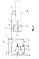
- the device comprises a processing and control unit, indicated overall by reference number 100, which receives an operating command 1 in input from a control panel or protection logic and sends a first control signal 3 in output to an actuator 2.
- the actuator used advantageously operates with an adjustable law of motion; in this way the force applied by the actuator to the switchgear 4, through a kinematic chain 5 connecting them, can be adjusted and makes it possible to have an actuator-kinematic chain-switchgear system 200 that is perfectly controlled in relation to the different application requirements using the procedures that will be illustrated in detail hereinafter.
- the actuator concerned is an electromagnetic actuator, the subject of European patent application number EP 97203501.8-2302, the description of which is to be understood as included herein for reference; the specific reference to said actuator is clearly to be considered solely for the purposes of explanation in that any actuator with adjustable law of motion, such as a pneumatic actuator for example, could be used in equivalent way in the device as in the invention.
- control device suitably comprises feedback means 6 for evaluating, by direct or indirect measurement, the position of the mobile part of the switchgear connected to the actuator; in particular, these means 6 may comprise a position sensor that detects a movement of any point of the controlled system 200 and sends a corresponding signal 7 indicating in real time the position of the mobile contacts of the switchgear to control means 10 of the processing and control unit 100; alternatively, velocity or acceleration sensors could be used that detect the velocity or the acceleration of any point of the system 200 and send the corresponding information 7 on the velocity or acceleration of the mobile parts to means 10.
- This sensor irrespective of whether it is a position, velocity or acceleration sensor, may be positioned in any point of the kinematic chain 5 or of the switchgear 4 to suit specific applications and/or needs.
- the information regarding the position of the mobile parts may be supplied to the control means 10 namely without the use of sensors ("sensorless system") using a mathematical model of the controlled system 200; this model, forming part of the unit 100, receives a signal in input that is a function of the actuator's control parameters, in this case the voltage and current of the power supply to the coil, and supplies a signal indicating the estimated position of the mobile contacts of the switchgear to the control means 10 in real time.
- the actuator used is, for example, a pneumatic type
- the control parameters could be the pressure and the volume of the compressible fluid used.
- the control means 10 which receive in input the operating command 1 and the direct or indirect signal 7 indicating the position or velocity or acceleration in real time of the mobile contacts of the switchgear, send a corresponding second control signal 19 to converter means 20 in output.
- control means 10 comprise calculating means 11 that receive the signal 7 in input and by means of suitable integrations/derivations send a signal 14 indicating the law of motion of the mobile contacts at that moment in output to first closed loop control means 12 and second closed loop control means 13; this signal 14 thus constitutes information of the mode in which the mobile part of the switchgear moves from the initial time of motion to the time of measurement.
- the first closed loop control means 12 compare the signal 14 indicating the actual law of motion of the mobile contacts with a predetermined law of motion and send a corresponding reference signal 16 in output to the second closed loop control means 13 and to comparator means 15.
- this predetermined law of motion corresponds to a predetermined nominal behaviour of the entire actuator-kinematic chain-switchgear system.
- the second closed loop control means 13 compare the signal indicating the actual law of motion 14 with the reference signal 16 sending a corresponding correction signal 18 in output to comparison means 15; the comparison means 15 in their turn send the second control signal 19 in output to converter means 20 in relation to the correction signal 18 and to the reference signal 16 received in input.
- the converter means 20 comprise power supply means 21 for the actuator that can be provided using, for example, batteries or capacitors; alternatively, in the case of an actuator that is not electromagnetic but can nevertheless be controlled, such as a pneumatic actuator, this storage unit could be provided using a compressible fluid plenum chamber.
- the converter means 20 advantageously comprise means for modulating 22 the flow of energy supplied to the actuator by the power supply means 21; these modulation means adjust the flow of energy supplied by the means 21 to the actuator by modulating the power supply current and/or voltage of the actuator itself in relation to the second control signal 19.
- the actuator which converts the modulated electrical energy into mechanical energy, thus applies a continually adjusted force to the kinematic loop connected to it that makes it possible to move the mobile parts of the switchgear with the desired law of motion.
- the control device proposed thus comprises an open loop control based on the nominal behaviour of the system to realise the opening and/or closing operation in the modes desired; this open loop control system is juxtaposed with a closed loop control system that corrects any possible changes in relation to the nominal behaviour to ensure implementation of the desired law of motion.
- the device as in the invention makes it possible to accurately take into account all the disturbance acting on the controlled system able to influence its response by varying the behaviour in relation to the predetermined nominal behaviour, namely the effect of environmentalparameters, the electrical and mechanical wear of the switchgear, the time elapsed between operations, the ageing of the control equipment, the number and type of operations performed etc..
- control device as in the invention makes it possible to obtain optimal operation on a single pole while leaving the other two phases, which are not affected by faults, in operation; furthermore, by adjusting the force applied by the actuator it is possible to stop an operation that has been started whenever it is no longer essential, or even to reverse the direction of the operation itself at least within a certain time window.
- circuit-breakers that, once an operation has already been started, are able to detect the operation of a circuit-breaker downstream that eliminates the fault and cancel the operation, preventing the circuit-breakers from opening and cutting off the power to fault-free parts of the electrical network without reason, also doing so without having to insert any intentional delays, useful for the purposes of selectivity.
- the circuit-breaker that is controlled can, when required to operate on a transient, cancel the operation when the transient is over and not interrupt the service of the loads that it powers.
- the device as in the invention ensures repeatability of the operation by adjusting the force applied by the actuator and makes it possible to optimise the law of motion of the mobile parts moment by moment following a preferred trajectory and in relation to the different types of breaking systems used; in this way, moreover, the energy transmitted to the actuator, and therefore to the switchgear, is adjusted perfectly and this makes it possible not just to optimise the sizing of the actuator and its power supply system, but also to decrease the energy dissipated in the end-of-operation impact, with lower stresses on the switchgear, lower contact wear and therefore, in short, higher reliability of the entire electrical network.
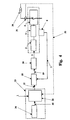
- the processing and control unit 100 also comprises synchronisation means 33 capable of providing information for the opening or closing of the switchgear synchronously with the electrical network.
- synchronisation means through the use of means for detecting the voltage and current phases of the electrical network, such as, for example, a current transformer 30 and a voltage transformer 31, receive information 32 tracking the electrical parameters of the network; in relation to this information, the synchronisation means, through suitable calculations, predict the succession of the zeros and maximums of the phases of the current and voltage following those detected, also taking account of frequency variations, harmonic components and single-phase transient components. In addition, they calculate the time between the zeros and maximums detected and those predicted.
- the synchronisation means advantageously also comprise table means 34 that contain predetermined information regarding the state of the neutral, the type of load and of the electrical network, and send a signal 35 indicating the ideal end-of-operation times in relation to said predetermined information to a timer unit 36.
- the operating command 1 is sent to the timer unit 36 and is a command that is generally asynchronous in relation to the electrical system.
- the timer unit 36 sends a corresponding synchronous start operation command 37 to the control means 10 in relation to this command 1, as well as to the signal 35 indicating the ideal end-of-operation times; this synchronous command 37 is delayed in relation to the asynchronous command 1 by a period of time 50 that is a function of the predetermined nominal operating time 51 and of the said signals 35 indicating the ideal end-of-operation times and the subsequent zeros or maximums predicted, in order to identify the first subsequent ideal moment useful for implementing the synchronous operation.
- the desired ideal moment 35 is clearly the optimal time for eliminating operation transients in relation to the type of operation, load and electrical network; as illustrated in Figure 6, this moment in time does not necessarily coincide with a zero or with a maximum but nevertheless ensures that the operation is performed within the synchronism window.
- the control means 10 thus receive the signal 37 indicating the co-ordinated control strategy for the three phases to perform the synchronous operation for each individual phase and operate analogously to that which has been described above.
- a further advantage of the invention resides in the fact that, both in the synchronous operation situation and in the case only of adjustment of the law of motion of the mobile parts previously described, the control means 10 ensure execution of the operation in the nominal time envisaged thanks to the corrective action of the means 13 previously described; if, however, the deviation from the nominal behaviour at any point become accentuated during the operation, requiring a significant demand on the closed loop control, the device is able to correct the nominal characteristic of the system in a self-organising mode.
- the nominal operation time that is suitably monitored during the operations is redefined in relation to a new reference value; in the case of synchronous operation, this new reference time is obviously made available by the means 10 to the timer unit 36.
- This self-organising procedure is also used in the device's testing phase so that the control system corrects the nominal characteristic in relation to the real behaviour of the specific switchgear unit, making it possible to define the actual initial nominal characteristic.
- the device as in the invention makes it possible to achieve the task in full as well as the objects set in that it makes it possible to adjust the force applied by the actuator in real time moving the mobile parts following a desired law of motion and making it possible to obtain all the advantages previously described.
- the device makes it possible to obtain operation synchronous with the electrical network, with the widest different types of electrical systems and loads present in them and even in the presence of faults. This therefore results in further and significant advantages in terms of the flexibility of application of the device, and in terms of the elimination or at least significant reduction of voltage and current transients in the network, as well as in terms of limiting electrodynamic and thermal stresses, with significant consequent benefits both for the insulation systems of the components present in the electrical system and of the switchgear used, considerably increasing its useful life and reliability.
- the device as in the invention while offering all the benefits stated, is obtained using a manufacturing solution that is extremely attractive from an economic standpoint, the costs of which are comparable with those of a conventional circuit-breaker and decidedly lower than the conventional synchronous solutions.
- the device conceived in this way is capable of many modifications and variants, all within the inventive concept, as defined in the appended claims.
Landscapes
- Engineering & Computer Science (AREA)
- Manufacturing & Machinery (AREA)
- Power Engineering (AREA)
- Remote Monitoring And Control Of Power-Distribution Networks (AREA)
- Keying Circuit Devices (AREA)
- Electrical Discharge Machining, Electrochemical Machining, And Combined Machining (AREA)
- Power-Operated Mechanisms For Wings (AREA)
Claims (16)
- Steuervorrichtung für eine elektrische Schalteinrichtung (4) umfassend:einen Aktuator (2) mit einstellbarem Bewegungsgesetz;eine kinematische Kette (5), welche den Aktuator (2) mit der Schalteinrichtung (4) verbindet;eine Verarbeitungs- und Steuereinheit (100), welche einen Operationsbefehl (1) empfängt und ein erstes Steuersignal (3) an den Aktuator (2) sendet, wobei die Verarbeitungs- und Steuereinheit (100) Steuermittel (10) umfasst, dadurch gekennzeichnet, dass das Steuermittel (10) umfasst:Berechnungsmittel (11), welche ein direktes oder indirektes Signal (7) empfangen, welches anzeigend für die Position, oder Geschwindigkeit, oder Beschleunigung in Echtzeit der beweglichen Kontakte der Schalteinrichtung ist und ein Signal (14) senden, welches anzeigend für das Bewegungsgesetz der beweglichen Kontakte ist;erste geschlossene Regelkreissteuermittel (12), welche das Signal (14) empfangen, welches anzeigend für das Bewegungsgesetz der beweglichen Kontakte ist, das Signal (14), welches anzeigend für das Bewegungsgesetz der beweglichen Kontakte ist, mit einem vorherbestimmten nominellen Verhalten des gesamten Systems Aktuator-kinematische Kette-Schalteinrichtung (200) vergleichen, und ein entsprechendes Referenzsignal (16) senden;zweite geschlossene Regelkreissteuermittel (13), welche das Signal (14), das anzeigend für das Bewegungsgesetz der beweglichen Kontakte ist, und das Referenzsignal (16) empfangen, und ein Korrektursignal (18) senden;Vergleichsmittel (15), welche das Referenzsignal (16), das anzeigend für das Bewegungsgesetz der beweglichen Kontakte ist, und das Korrektursignal (18) empfangen, und ein zweites Steuersignal (19) senden, um ein gewünschtes Bewegungsgesetz der beweglichen Kontakte zu verwirklichen.
- Steuervorrichtung nach Anspruch 1, dadurch gekennzeichnet, dass der Aktuator (2) mit einstellbarem Bewegungsgesetz ein elektromagnetischer Aktuator ist.
- Steuervorrichtung nach Anspruch 1 oder 2, dadurch gekennzeichnet, dass es Feedback-Mittel (6) umfasst zum Bewerten durch direkte oder indirekte Messung der Position des beweglichen Teils des Systems (200).
- Steuervorrichtung nach Anspruch 3, dadurch gekennzeichnet, dass die Feed-back-Mittel (6) einen Positions- oder Geschwindigkeits- oder Beschleunigungssensor umfassen, welcher die Position oder Geschwindigkeit oder Beschleunigung irgendeines Punktes des Systems (200) erkennt und das Signal (7), das anzeigend für die Position, oder Geschwindigkeit, oder Beschleunigung in Echtzeit der beweglichen Kontakte der Schalteinrichtung (4) ist, sendet.
- Steuervorrichtung nach Anspruch 3, dadurch gekennzeichnet, dass die Feed-back-Mittel (6) ein mathematisches Modell des Systems (200) umfassen, welches ein Signal in Eingang empfängt, das eine Funktion der Messungen von Steuerparametern des Aktuators ist und ein Signal (7) sendet, welches anzeigend für die geschätzte Position der beweglichen Kontakte der Schalteinrichtung (4) ist, an die Verarbeitungs- und Steuereinheit (100) in Echtzeit.
- Steuervorrichtung nach einem oder mehreren der vorhergehenden Ansprüche, dadurch gekennzeichnet, dass es Konvertermittel (20) umfasst, welche in Eingang das zweite Steuersignal (19) empfangen, wobei die Konvertermittel (20) umfassen:Stromversorgungsmittel (21) für den Aktuator (2); undMittel (22) zum Modulieren des Flusses von Energie, welche dem Aktuator (2) durch die Stromversorgungsmittel (21) bereitgestellt wird, in Beziehung auf das zweite Steuersignal (19), welches in Eingang empfangen wurde.
- Steuervorrichtung nach einem oder mehreren der vorhergehenden Ansprüche, dadurch gekennzeichnet, dass es Synchronisationsmittel (33) umfasst, die dazu geeignet sind, die Verarbeitungs- und Steuereinheit (100) mit Information zu versehen zum Öffnen oder Schließen der Schalteinrichtung (4) in einem Modus, der synchron mit dem elektrischen Netzwerk ist.
- Steuervorrichtung nach Anspruch 7, dadurch gekennzeichnet, dass die Synchronisationsmittel (33) umfassen:Mittel (30, 31) zum Erkennen der Strom- und Spannungsphasen des elektrischen Netzwerks;Mittel zum Vorhersagen der Nulldurchgänge und Maxima der Strom- und Spannungsphasen, nachfolgend zu den erkannten;Mittel zum Berechnen der Zeitperiode zwischen den erkannten und den vorhergesagten Nulldurchgängen und Maxima.
- Steuervorrichtung nach Anspruch 7 oder 8, dadurch gekennzeichnet, dass die Synchronisationsmittel (33) umfassen:Tabellenmittel (34), welche vorherbestimmte Information enthalten bzgl. des Zustands des Neutralleiters, der Art der Last und der Art des elektrischen Netzwerks, wobei die Tabellenmittel (34) geeignet sind zum Senden eines Signals (35), das anzeigend für die ideale Ende-der-Operationszeit in Beziehung zu der vorherbestimmten Information ist, an eine Timereinheit (36) zu senden.
- Steuervorrichtung nach Anspruch 9, dadurch gekennzeichnet, dass die Timereinheit (36) in Eingang empfängt:und an die Steuermittel (10) einen entsprechenden synchronen Startoperationsbefehl (37) senden, der verzögert ist in Beziehung auf den asynchronen Befehl (1) um eine Zeitperiode (50), die eine Funktion einer vorherbestimmten nominellen Operationszeit (51) und des Signals (35), das anzeigend für die ideale Ende-der-Operationszeiten ist, und des Signals, welches anzeigend für die nachfolgend vorhergesagten Nulldurchgänge oder Maxima ist, ist.den Operationsbefehl (1), der asynchron in Beziehung zu dem elektrischen System ist;das Signal (35), welches anzeigend für die ideale Ende-der-Operationszeiten ist;ein Signal anzeigend für die nachfolgend vorhergesagten Nulldurchgänge oder Maxima;
- Elektrisches Verteilungs- und/oder Übertragungsnetzwerk, umfassend eine Vielzahl von Trennschaltern, welche in einer Kaskadenanordnung installiert sind, dadurch gekennzeichnet, dass wenigstens ein Trennschalter aus der Vielzahl eine Steuervorrichtung nach einem oder mehreren der vorhergehenden Ansprüche umfasst, und dass das Öffnen/Schließen des wenigstens einen Trennschalters in einer Weise erfolgt, die koordiniert mit anderen übergeordneten oder nachfolgenden Trennschaltern ist, um die Öffnungs- oder Schließoperation zu unterbrechen oder umzukehren.
- Elektrische Schalteinrichtung für elektrische Verteilungs- und/oder Übertragungsnetzwerke, dadurch gekennzeichnet, dass es eine Steuervorrichtung nach einem oder mehreren der Ansprüche 1 bis 10 umfasst, und darin, dass der Betrag der abgegebenen Leistung während einer Öffnungs-/Schließoperation eine Funktion, Augenblick um Augenblick, des Restwegs der beweglichen Kontakte ist.
- Elektrische Schalteinrichtung nach Anspruch 12, dadurch gekennzeichnet, dass der einstellbare Aktuator auf den beweglichen Teil Kraft anwendet, welche Augenblick um Augenblick einstellbar ist, und in der Lage ist, den Betrag der Energie zu minimieren, welche in dem Anschlag in einer Schließoperation umgesetzt wird.
- Steuerverfahren für das Öffnen/Schließen von elektrischen Schalteinrichtungen (4), wie Trennschalter, Isolatoren, Kurzunterbrechern und ähnlichem, in einem elektrischen Versorgungs- und/oder Übertragungsnetzwerk, dadurch gekennzeichnet, dass es die folgenden Phasen umfasst:a) Senden eines Operationsbefehls (1) an eine Verarbeitungs- und Steuereinheit (100) der Schalteinrichtung (4);b) direktes oder indirektes Erfassen von Information (7) der Bewegung oder Geschwindigkeit oder Beschleunigung in Echtzeit der beweglichen Kontakte der Schalteinrichtung (4) und Senden eines Signals (14), welches anzeigend für das Bewegungsgesetz der beweglichen Kontakte ist;c) Vergleichen des Signals (14), das anzeigend für das Bewegungsgesetz der beweglichen Kontakte ist, mit einem Signal, welches anzeigend für ein vorherbestimmtes Bewegungsgesetz ist, und Senden eines entsprechenden Referenzsignals (16);d) Vergleichen des Referenzsignals (16) mit dem Signal (14), welches anzeigend für das Bewegungsgesetz der beweglichen Kontakte ist, und, in Beziehung auf diesen Vergleich, Senden eines Korrektursignals (18);e) Vergleichen des Korrektursignals (18) mit dem Referenzsignal (16) und, in Beziehung auf dieses Vergleichen, Senden eines zweiten Steuersignals (19);f) Modulieren des Flusses von Energie, welche an den Aktuator (2) mit einstellbarem Bewegungsgesetz bereitgestellt wird, in Beziehung auf das zweite Steuersignal (19), um die Kraft, die er auf das kinematische Kette-Schalteinrichtungssystem ausübt, anzupassen, um ein gewünschtes Bewegungsgesetz der beweglichen Kontakte zu erhalten;g) Senden eines ersten Steuersignals (3) an den Aktuator.
- Steuerverfahren nach Anspruch 14, dadurch gekennzeichnet, dass, die Phase a) umfasst:Erkennen der Strom- (30) und Spannungsphasen (31) des elektrischen Netzwerks;Vorhersagen der Nulldurchgänge und Maxima der Strom- und Spannungsphasen, nachfolgend zu den erkannten;Berechnen der Zeitperiode zwischen den erkannten und den vorhergesagten Nulldurchgängen und Maxima;Verarbeiten und Senden eines Operationsbefehls (37), um die Operation synchron mit dem elektrischen Netzwerk zu machen.
- Steuerverfahren nach Anspruch 15, dadurch gekennzeichnet, dass die Phase des Verarbeitens und Sendens eines Operationsbefehls (37) um die Oparation synchron mit dem elektrischen Netzwerk zu machen umfasst:Erfassen eines Signals (35), welches anzeigend für die idealen Ende-der-Operationszeiten in Beziehung auf vorherbestimmte Information bzgl. des Zustands des Neutralleiters, der Art der Last und der Art des elektrischen Netzwerks ist;Senden des Operationsbefehls (37), verzögert in Beziehung auf einen asynchronen Befehl (1) um eine Zeitperiode (50), welche eine Funktion einer vorherbestimmten nominalen Operationszeit (51) ist, des Signals (35) anzeigend für die ideale Ende-der-Operationszeiten und von nachfolgenden vorhergesagten Nulldurchgängen oder Maxima.
Priority Applications (7)
| Application Number | Priority Date | Filing Date | Title |
|---|---|---|---|
| DE69829057T DE69829057T2 (de) | 1998-12-03 | 1998-12-03 | Vorrichtung zur Regelung der Öffnung und Schliessung eines elektrisches Schaltgerätes und verwandtes Verfahren |
| EP98204083A EP1006537B1 (de) | 1998-12-03 | 1998-12-03 | Vorrichtung zur Regelung der Öffnung und Schliessung eines elektrisches Schaltgerätes und verwandtes Verfahren |
| ES98204083T ES2237823T3 (es) | 1998-12-03 | 1998-12-03 | Dispositivo para el control de un aparato de conmutacion electrica y procedimiento asociado. |
| AT98204083T ATE289449T1 (de) | 1998-12-03 | 1998-12-03 | Vorrichtung zur regelung der öffnung und schliessung eines elektrisches schaltgerätes und verwandtes verfahren |
| TW088118962A TW501155B (en) | 1998-12-03 | 1999-11-11 | Device for controlling the opening/closing of electrical switchgear and related procedure |
| CNB991258789A CN1263056C (zh) | 1998-12-03 | 1999-12-02 | 用于控制电开关装置的打开与闭合的装置和方法 |
| KR1019990054628A KR20000047875A (ko) | 1998-12-03 | 1999-12-03 | 전기 개폐기의 개폐를 제어하는 장치 및 개폐 과정 |
Applications Claiming Priority (1)
| Application Number | Priority Date | Filing Date | Title |
|---|---|---|---|
| EP98204083A EP1006537B1 (de) | 1998-12-03 | 1998-12-03 | Vorrichtung zur Regelung der Öffnung und Schliessung eines elektrisches Schaltgerätes und verwandtes Verfahren |
Publications (2)
| Publication Number | Publication Date |
|---|---|
| EP1006537A1 EP1006537A1 (de) | 2000-06-07 |
| EP1006537B1 true EP1006537B1 (de) | 2005-02-16 |
Family
ID=8234422
Family Applications (1)
| Application Number | Title | Priority Date | Filing Date |
|---|---|---|---|
| EP98204083A Expired - Lifetime EP1006537B1 (de) | 1998-12-03 | 1998-12-03 | Vorrichtung zur Regelung der Öffnung und Schliessung eines elektrisches Schaltgerätes und verwandtes Verfahren |
Country Status (7)
| Country | Link |
|---|---|
| EP (1) | EP1006537B1 (de) |
| KR (1) | KR20000047875A (de) |
| CN (1) | CN1263056C (de) |
| AT (1) | ATE289449T1 (de) |
| DE (1) | DE69829057T2 (de) |
| ES (1) | ES2237823T3 (de) |
| TW (1) | TW501155B (de) |
Families Citing this family (15)
| Publication number | Priority date | Publication date | Assignee | Title |
|---|---|---|---|---|
| DE19963256C1 (de) * | 1999-12-17 | 2001-05-23 | Siemens Ag | Hochspannungs-Leistungsschalter |
| KR100390547B1 (ko) * | 2001-03-31 | 2003-07-07 | 한국전기연구원 | 송전선로용 차단기의 투입 제어방법 |
| JP5355187B2 (ja) * | 2009-04-03 | 2013-11-27 | 株式会社東芝 | 遮断器の開閉制御システム |
| EP2395365A1 (de) * | 2009-04-22 | 2011-12-14 | Omicron electronics GmbH | Vorrichtung und Verfahren zum Testen eines elektrischen Schalters nach einem Umbau oder einer Revision |
| US9837229B2 (en) | 2011-06-24 | 2017-12-05 | Tavrida Electric Holding Ag | Method and apparatus for controlling circuit breaker operation |
| CN103296760A (zh) * | 2013-06-04 | 2013-09-11 | 国家电网公司 | 一种高压隔离开关的在线监测系统 |
| CN103545133A (zh) * | 2013-09-27 | 2014-01-29 | 国家电网公司 | 高压交流相控断路器及其选相位分/合闸控制方法 |
| CN103558777B (zh) * | 2013-10-29 | 2016-06-08 | 郭辉 | 煤矿非用即停电源控制装置 |
| KR101580282B1 (ko) * | 2015-06-22 | 2016-01-04 | (주)부영이엔지 | 변전소 변전 설비용 개폐장치 진단 방법 |
| CN106328406A (zh) * | 2016-08-26 | 2017-01-11 | 孟玲 | 高压交流断路器分合闸控制器 |
| WO2018224155A1 (en) * | 2017-06-08 | 2018-12-13 | Abb Schweiz Ag | Monitoring device for switching systems |
| FR3069064B1 (fr) * | 2017-07-13 | 2022-02-11 | Schneider Electric Ind Sas | Dispositif de commutation electrique et procede de detection d'usure associe |
| EP3723110B1 (de) * | 2019-04-12 | 2025-10-29 | ABB Schweiz AG | Synchronisiertes öffnen eines leistungsschalters |
| EP3754682B1 (de) | 2019-06-19 | 2023-08-02 | ABB Schweiz AG | Verbesserte mittelspannungsschaltanlage |
| CN110676092B (zh) * | 2019-10-18 | 2025-02-28 | 中国铁道科学研究院集团有限公司 | 基于开关设备多路反馈信号的控制系统 |
Family Cites Families (3)
| Publication number | Priority date | Publication date | Assignee | Title |
|---|---|---|---|---|
| DE2601799A1 (de) * | 1976-01-20 | 1977-07-21 | Licentia Gmbh | Schaltanordnung zur betaetigung eines elektromagnetsystems |
| US5644463A (en) * | 1992-10-20 | 1997-07-01 | University Of Washington | Adaptive sequential controller with minimum switching energy |
| KR100438526B1 (ko) * | 1995-05-15 | 2004-09-10 | 쿠퍼 인더스트리스, 인코포레이티드 | 스위치기어액츄에이터용제어장치와방법 |
-
1998
- 1998-12-03 AT AT98204083T patent/ATE289449T1/de not_active IP Right Cessation
- 1998-12-03 ES ES98204083T patent/ES2237823T3/es not_active Expired - Lifetime
- 1998-12-03 DE DE69829057T patent/DE69829057T2/de not_active Expired - Lifetime
- 1998-12-03 EP EP98204083A patent/EP1006537B1/de not_active Expired - Lifetime
-
1999
- 1999-11-11 TW TW088118962A patent/TW501155B/zh not_active IP Right Cessation
- 1999-12-02 CN CNB991258789A patent/CN1263056C/zh not_active Expired - Lifetime
- 1999-12-03 KR KR1019990054628A patent/KR20000047875A/ko not_active Ceased
Also Published As
| Publication number | Publication date |
|---|---|
| TW501155B (en) | 2002-09-01 |
| DE69829057T2 (de) | 2005-12-29 |
| CN1263056C (zh) | 2006-07-05 |
| KR20000047875A (ko) | 2000-07-25 |
| ES2237823T3 (es) | 2005-08-01 |
| DE69829057D1 (de) | 2005-03-24 |
| CN1255716A (zh) | 2000-06-07 |
| EP1006537A1 (de) | 2000-06-07 |
| ATE289449T1 (de) | 2005-03-15 |
Similar Documents
| Publication | Publication Date | Title |
|---|---|---|
| EP1006537B1 (de) | Vorrichtung zur Regelung der Öffnung und Schliessung eines elektrisches Schaltgerätes und verwandtes Verfahren | |
| US9263213B2 (en) | Power switching control device and closing control method thereof | |
| US7982341B2 (en) | Transformer operation control apparatus and method for suppressing magnetizing inrush current | |
| EP1069579B1 (de) | Betätigung und Steuervorrichtung für elektrische Schaltanlage | |
| US10177553B2 (en) | Power switching control apparatus and switching control method therefor | |
| EP3723110A1 (de) | Synchronisiertes öffnen eines leistungsschalters | |
| US20040130835A1 (en) | Method and arrangement for reducing stress in electrical network | |
| CA2211907A1 (en) | Dynamic mechanically switched damping system and method for damping power oscillations using the same | |
| US7227732B2 (en) | Apparatus and method for controlling open/close timing of relay | |
| JPWO2015056289A1 (ja) | 電力開閉制御装置および閉極制御方法 | |
| EP1006539B1 (de) | Steuer- und Überwachungseinrichtung für die Öffnung oder die Schliessung eines elektrischen Betätigungselementes | |
| US11670471B2 (en) | Low energy reclosing pulse test | |
| Ciulica | Optimizing the switching time for 400 kV SF6 circuit breakers | |
| Liu et al. | Optimizing the arcing time for smart circuit breakers using synchronous phase control | |
| Desai et al. | Adaptive Out-of-Step Protection of Synchronous Generator | |
| Hauer et al. | Benchmark tests of single-break and double-break design principles | |
| JP5517865B2 (ja) | 発電プラントの発電機電圧制御システム | |
| Kanta et al. | Evaluation of Controlled Energization Zone of a Circuit Breaker using Binary Search Algorithm | |
| Maheshwari et al. | Multiprocessor Based Architecture for Controlled Switching of Circuit Breaker | |
| JPH05144352A (ja) | 真空遮断器 |
Legal Events
| Date | Code | Title | Description |
|---|---|---|---|
| PUAI | Public reference made under article 153(3) epc to a published international application that has entered the european phase |
Free format text: ORIGINAL CODE: 0009012 |
|
| AK | Designated contracting states |
Kind code of ref document: A1 Designated state(s): AT BE CH DE DK ES FI FR GB GR IT LI NL SE |
|
| AX | Request for extension of the european patent |
Free format text: AL;LT;LV;MK;RO;SI |
|
| 17P | Request for examination filed |
Effective date: 20001122 |
|
| AKX | Designation fees paid |
Free format text: AT BE CH DE DK ES FI FR GB GR IT LI NL SE |
|
| 17Q | First examination report despatched |
Effective date: 20030414 |
|
| GRAP | Despatch of communication of intention to grant a patent |
Free format text: ORIGINAL CODE: EPIDOSNIGR1 |
|
| GRAS | Grant fee paid |
Free format text: ORIGINAL CODE: EPIDOSNIGR3 |
|
| GRAA | (expected) grant |
Free format text: ORIGINAL CODE: 0009210 |
|
| AK | Designated contracting states |
Kind code of ref document: B1 Designated state(s): AT BE CH DE DK ES FI FR GB GR IT LI NL SE |
|
| PG25 | Lapsed in a contracting state [announced via postgrant information from national office to epo] |
Ref country code: NL Free format text: LAPSE BECAUSE OF FAILURE TO SUBMIT A TRANSLATION OF THE DESCRIPTION OR TO PAY THE FEE WITHIN THE PRESCRIBED TIME-LIMIT Effective date: 20050216 Ref country code: LI Free format text: LAPSE BECAUSE OF FAILURE TO SUBMIT A TRANSLATION OF THE DESCRIPTION OR TO PAY THE FEE WITHIN THE PRESCRIBED TIME-LIMIT Effective date: 20050216 Ref country code: FI Free format text: LAPSE BECAUSE OF FAILURE TO SUBMIT A TRANSLATION OF THE DESCRIPTION OR TO PAY THE FEE WITHIN THE PRESCRIBED TIME-LIMIT Effective date: 20050216 Ref country code: CH Free format text: LAPSE BECAUSE OF FAILURE TO SUBMIT A TRANSLATION OF THE DESCRIPTION OR TO PAY THE FEE WITHIN THE PRESCRIBED TIME-LIMIT Effective date: 20050216 Ref country code: BE Free format text: LAPSE BECAUSE OF FAILURE TO SUBMIT A TRANSLATION OF THE DESCRIPTION OR TO PAY THE FEE WITHIN THE PRESCRIBED TIME-LIMIT Effective date: 20050216 Ref country code: AT Free format text: LAPSE BECAUSE OF FAILURE TO SUBMIT A TRANSLATION OF THE DESCRIPTION OR TO PAY THE FEE WITHIN THE PRESCRIBED TIME-LIMIT Effective date: 20050216 |
|
| REG | Reference to a national code |
Ref country code: GB Ref legal event code: FG4D |
|
| REG | Reference to a national code |
Ref country code: CH Ref legal event code: EP |
|
| REF | Corresponds to: |
Ref document number: 69829057 Country of ref document: DE Date of ref document: 20050324 Kind code of ref document: P |
|
| PG25 | Lapsed in a contracting state [announced via postgrant information from national office to epo] |
Ref country code: SE Free format text: LAPSE BECAUSE OF FAILURE TO SUBMIT A TRANSLATION OF THE DESCRIPTION OR TO PAY THE FEE WITHIN THE PRESCRIBED TIME-LIMIT Effective date: 20050516 Ref country code: DK Free format text: LAPSE BECAUSE OF FAILURE TO SUBMIT A TRANSLATION OF THE DESCRIPTION OR TO PAY THE FEE WITHIN THE PRESCRIBED TIME-LIMIT Effective date: 20050516 |
|
| REG | Reference to a national code |
Ref country code: GR Ref legal event code: EP Ref document number: 20050401506 Country of ref document: GR |
|
| NLV1 | Nl: lapsed or annulled due to failure to fulfill the requirements of art. 29p and 29m of the patents act | ||
| REG | Reference to a national code |
Ref country code: ES Ref legal event code: FG2A Ref document number: 2237823 Country of ref document: ES Kind code of ref document: T3 |
|
| REG | Reference to a national code |
Ref country code: CH Ref legal event code: PL |
|
| PLBE | No opposition filed within time limit |
Free format text: ORIGINAL CODE: 0009261 |
|
| STAA | Information on the status of an ep patent application or granted ep patent |
Free format text: STATUS: NO OPPOSITION FILED WITHIN TIME LIMIT |
|
| ET | Fr: translation filed | ||
| 26N | No opposition filed |
Effective date: 20051117 |
|
| PGFP | Annual fee paid to national office [announced via postgrant information from national office to epo] |
Ref country code: GR Payment date: 20081218 Year of fee payment: 11 |
|
| REG | Reference to a national code |
Ref country code: FR Ref legal event code: PLFP Year of fee payment: 18 |
|
| REG | Reference to a national code |
Ref country code: FR Ref legal event code: PLFP Year of fee payment: 19 |
|
| REG | Reference to a national code |
Ref country code: FR Ref legal event code: PLFP Year of fee payment: 20 |
|
| PGFP | Annual fee paid to national office [announced via postgrant information from national office to epo] |
Ref country code: DE Payment date: 20171211 Year of fee payment: 20 Ref country code: FR Payment date: 20171221 Year of fee payment: 20 |
|
| PGFP | Annual fee paid to national office [announced via postgrant information from national office to epo] |
Ref country code: GB Payment date: 20171221 Year of fee payment: 20 |
|
| PGFP | Annual fee paid to national office [announced via postgrant information from national office to epo] |
Ref country code: ES Payment date: 20180123 Year of fee payment: 20 |
|
| PGFP | Annual fee paid to national office [announced via postgrant information from national office to epo] |
Ref country code: IT Payment date: 20171221 Year of fee payment: 20 |
|
| REG | Reference to a national code |
Ref country code: DE Ref legal event code: R071 Ref document number: 69829057 Country of ref document: DE |
|
| REG | Reference to a national code |
Ref country code: GB Ref legal event code: PE20 Expiry date: 20181202 |
|
| PG25 | Lapsed in a contracting state [announced via postgrant information from national office to epo] |
Ref country code: GB Free format text: LAPSE BECAUSE OF EXPIRATION OF PROTECTION Effective date: 20181202 |
|
| REG | Reference to a national code |
Ref country code: ES Ref legal event code: FD2A Effective date: 20200724 |
|
| PG25 | Lapsed in a contracting state [announced via postgrant information from national office to epo] |
Ref country code: ES Free format text: LAPSE BECAUSE OF EXPIRATION OF PROTECTION Effective date: 20181204 |