EP1006548B1 - Hochspannungsschalter - Google Patents
Hochspannungsschalter Download PDFInfo
- Publication number
- EP1006548B1 EP1006548B1 EP98870264A EP98870264A EP1006548B1 EP 1006548 B1 EP1006548 B1 EP 1006548B1 EP 98870264 A EP98870264 A EP 98870264A EP 98870264 A EP98870264 A EP 98870264A EP 1006548 B1 EP1006548 B1 EP 1006548B1
- Authority
- EP
- European Patent Office
- Prior art keywords
- blades
- distance
- central axis
- movable shaft
- switch according
- Prior art date
- Legal status (The legal status is an assumption and is not a legal conclusion. Google has not performed a legal analysis and makes no representation as to the accuracy of the status listed.)
- Expired - Lifetime
Links
- 229920000515 polycarbonate Polymers 0.000 claims description 2
- 239000004417 polycarbonate Substances 0.000 claims description 2
- 238000010891 electric arc Methods 0.000 description 13
- 238000009423 ventilation Methods 0.000 description 11
- 230000008033 biological extinction Effects 0.000 description 5
- 241000940835 Pales Species 0.000 description 3
- 206010033546 Pallor Diseases 0.000 description 3
- 230000000694 effects Effects 0.000 description 2
- 238000010276 construction Methods 0.000 description 1
- 238000007796 conventional method Methods 0.000 description 1
- 230000004907 flux Effects 0.000 description 1
- 239000011810 insulating material Substances 0.000 description 1
- 238000009413 insulation Methods 0.000 description 1
- 239000007769 metal material Substances 0.000 description 1
- 230000007935 neutral effect Effects 0.000 description 1
- 238000010791 quenching Methods 0.000 description 1
- 230000000171 quenching effect Effects 0.000 description 1
- 230000008929 regeneration Effects 0.000 description 1
- 238000011069 regeneration method Methods 0.000 description 1
Images


Classifications
-
- H—ELECTRICITY
- H01—ELECTRIC ELEMENTS
- H01H—ELECTRIC SWITCHES; RELAYS; SELECTORS; EMERGENCY PROTECTIVE DEVICES
- H01H33/00—High-tension or heavy-current switches with arc-extinguishing or arc-preventing means
- H01H33/70—Switches with separate means for directing, obtaining, or increasing flow of arc-extinguishing fluid
- H01H33/88—Switches with separate means for directing, obtaining, or increasing flow of arc-extinguishing fluid the flow of arc-extinguishing fluid being produced or increased by movement of pistons or other pressure-producing parts
- H01H33/886—Switches with separate means for directing, obtaining, or increasing flow of arc-extinguishing fluid the flow of arc-extinguishing fluid being produced or increased by movement of pistons or other pressure-producing parts by movement of rotating pistons
-
- H—ELECTRICITY
- H01—ELECTRIC ELEMENTS
- H01H—ELECTRIC SWITCHES; RELAYS; SELECTORS; EMERGENCY PROTECTIVE DEVICES
- H01H31/00—Air-break switches for high tension without arc-extinguishing or arc-preventing means
- H01H31/14—Air-break switches for high tension without arc-extinguishing or arc-preventing means with bridging contact that is not electrically connected to either line contact in open position of switch
- H01H31/16—Air-break switches for high tension without arc-extinguishing or arc-preventing means with bridging contact that is not electrically connected to either line contact in open position of switch with angularly-movable bridging contact or contact-carrying member
Definitions
- the present invention relates to a high-voltage switch comprising: a movable shaft arranged to be displaced in rotation along an axis of rotation between a latching and tripping position, the movable shaft comprising first and second flanks on the one hand and other of the axis of rotation and a hole passing through the first and second sidewalls; a pair of movable contacts extending through the hole and extending beyond each of the first and second sidewalls; a first pair of fan blades comprising first and second blades extending on either side of the pair of movable contacts protruding from the first side of the movable shaft; a second pair of fan blades comprising third and fourth blades extending on either side of the pair of movable contacts protruding from the second side of the movable shaft; each blade having a central axis, a first side and a second side opposite the first side.
- Patent Application EP-A-0 518 837 describes an arrangement in which ventilation blades extend from the movable shaft and are connected to the sides of the shaft.
- the blades of a pair of blades are of identical shape but are positioned at different predetermined angles, so that when the movable shaft is rotated, turbulence is generated in the area around the arc.
- ionized gas present around the arc is displaced by fresh gas, which leads to extinction of the arc.
- each fan blade extends substantially perpendicular to the moving contacts; each of the first and fourth blades comprises first and second legs extending parallel to each other on either side of the central axis, each of the first and second legs comprising: an inner edge extending parallel to the central axis at a distance from distance D1 from the central axis; an outer edge extending parallel to the central axis at a distance D2 from the central axis; and each of the second and third blades comprises third and third fourth legs extending parallel on either side of the central axis, an opening being provided in each of the third and fourth legs, the opening being delimited by an inner edge located at a distance D5 from the central axis, the distance D5 being less than the distance D2; and an outer edge located at a distance D6 from the central axis, the distance D6 being greater than the distance D2.
- the first and third blades are connected by a first base and the second and fourth blades are connected by a second base.
- each movable contact has an outer face located at a distance D7 from the central axis of the blades, the distance D7 being less than the distance D1.
- FIG. 1 illustrates a preferred embodiment of an assembly according to the invention.
- a first ventilation blade 66 comprises a first tab 12 and a second tab 14 which extend parallel to each other on either side of the central axis 74 of the blades.
- a second ventilation blade 68 comprises a third leg 16 and a fourth leg 18 which also extend parallel to each other on either side of the central axis 74 of the blades.
- the first and second blades are of different shape and are connected by a base member 10.
- the blades are preferably reinforced polycarbonate having a thickness equal to less than 3 mm, in particular approximately equal to 2 mm. The chosen thickness guarantees a good blade flexibility.
- the first and second legs 12, 14 each have an inner edge 20, 22 and an outer edge 24, 26 extending parallel to the central axis.
- the inner edges 20, 22 are located at a distance D1 from the central axis.
- the outer edges 24 are located at a distance D2 from the central axis.
- the third and fourth legs 16, 18 each have an inner edge 28, 30 and an outer edge 32, 34 extending parallel to the central axis.
- the inner edges 28, 30 are located at a distance D3 from the central axis.
- the outer edges 32, 34 are located at a distance D4 from the central axis.
- the outer edges 32, 34 need not necessarily extend parallel to the central axis. According to an alternative, the outer edges 32, 34 extend at a predetermined angle relative to the central axis. It is also conceivable that the outer edge is curved.
- An opening 36 is provided in each of the third and fourth legs 16, 18.
- the opening 36 is rectangular in shape, which creates a turbulence zone to extinguish the electric arc effectively.
- the opening is delimited by an inner edge 37 and an outer edge 39.
- the inner edge 37 is located at a distance D5 from the central axis, while the outer edge 39 is located at a distance D6 from the central axis. It is important that the distance D5 is less than the distance D2 and that the distance D6 is greater than the distance D2, in order to guarantee a flow of fresh gas as well as a zone of turbulence around the electric arc, as it will be explained below with reference to Figure 5.
- the base 10 preferably includes notches 38, 40 arranged to fit in a stop member provided in the movable shaft, to ensure proper positioning of the assembly of Figure 1 relative to the movable shaft .
- FIG 2 is a perspective view of a portion of the switch according to the invention.
- a movable shaft 50 known as such, is arranged to be rotated about an axis of rotation 76.
- the movable shaft comprises a first side 54 and a second sidewall 56.
- the sidewalls are located on either side of the axis of rotation 76.
- the movable shaft shown in Figure 2 is arranged to be used in a three-pole switch. Therefore, it has three holes 58 crossing each of the first and second flanks.
- a pair of movable contacts 52 is housed.
- the movable contacts project out of the flanks 54 and 56 of the moving shaft.
- the blades are disposed substantially perpendicular to the main planes of the movable contacts.
- On the side of the first sidewall 54 extends a first pair of ventilation blades comprising a first blade 66 and a second blade 68.
- On the side of the second sidewall 56 extends a second pair of ventilation blades comprising a third 70 and a fourth blade 72.
- the fourth blade 72 is similar to the first blade 66
- the third blade 70 is similar to the second blade 68.
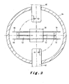
- FIG. 3 is a sectional front view of a switch according to the invention, comprising the assembly of FIG. 2.
- the assembly formed by the movable shaft 50, the movable contacts 52 and the ventilation blades 66, 68 , 70, 72 is housed in an envelope 64 known as such.
- a gas typically SF6 or other insulating gas, for example air.
- the gas contained in the envelope is under an absolute pressure of 1.5 bar maximum.
- the envelope itself can be made of an insulating material.
- the insulating envelope is of metallic material. In this case, insulation is provided around the fixed contacts 60, 62.
- Fixed contacts 60 and 62 are arranged on the casing so that they can be connected to each other via the movable contacts 52, when the movable shaft 50 is brought to the engagement position. I.
- the connection of the two fixed contacts 60 and 62 is interrupted. Since it is a double-break switch, the electric arc is formed at the height of the two fixed contacts when the rotary shaft is moved from the latching position I to the trigger position.
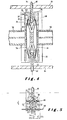
- FIG. 4 is a sectional side view of the switch according to Figure 3.
- Each opening 36 of the second and fourth blades is delimited by an inner edge 37, located at a distance D5 from the central axis 74, and an outer edge 39, located at a distance D6 from the axis.
- Each leg of the first and fourth blades comprises an outer edge 24 located at a distance D2 from the central axis. Overlap means that the distance D2 is greater than the distance D5, but less than the distance D6.
- springs 78 arranged to support the ends of the movable contacts 52 towards each other, so as to ensure good contact between the movable contacts and the fixed contacts 60 and 62.
- FIG. 5 is a detail illustrating the flow of gas when the switch is brought to a trigger position.
- an electric arc 80 is formed when the movable contacts 52 are moved from the latching position to the trigger position.
- a gas flow illustrated by the arrows, is created.
- the movable shaft is moved at a relatively high speed.
- the ends of the moving contacts are moved at a speed ranging from 5 to 9 meters per second. The speed is chosen in order to obtain a good balance between the mechanical properties of the blades and the electrical performances at this speed. Due to the shape and arrangement of the blades turbulence is created, which effectively extinguishes the electric arc.
- the distance D2 is less than the distance D6, but greater than the distance D5. Consequently, a portion of the flow of gas passing through the opening 36, abuts against the blade 66, while another portion passes beyond the outer edge 24 of the blade 66. This condition relative dimensions of the distances D2, D5 and D6 proved necessary for proper operation of the device.
- the inner edge 20 of the tab 66 is located at a distance D1 greater than the distance D7, the distance D7 being the distance of the outer face of the movable contacts relative to the central axis. This condition makes it possible to bring part of the flow of gas between the outer face of the moving contacts and the inner edge of the first and fourth blades.
- the flow of gas passes between the blade tabs and the opening of the second and third blades.
- the gas passing through the opening passes on the one hand between the outer face of the movable contacts and the inner edges of the first and fourth blades and on the other hand outside the outer edges 24 of the first and fourth blades.
- the inner edge 28 of the legs of the second and third blades 68, 70 is located at a distance D3 from the central axis. This distance D3 is preferably less than the distance D7.
- the gas flow generates a slight overpressure at the front of the blades in the direction of release (indicated by the arrow O), while a slight depression is generated at the rear of the blades. This results in a turbulence of the insulating gas, forcing it to converge towards the electric arc zone.
- This dynamic effect on the insulating gas allows a fast regeneration of the ionized insulating gas in the electric arc zone, which contributes efficiently and quickly to the extinction of the arc.
- the present invention is not limited to three-pole connections.
- the number of poles may be different; it can for example be applied in bipolar or unipolar switches.
- For each pole a pair of movable contacts as well as first and second pairs of blades are disposed in the movable shaft as described above.
- the blades illustrated in the figures are arranged to be housed removably in the movable shaft.
- the blades are integrated with the movable shaft and the assembly is molded in one piece.
- the present invention can also be applied in a three-position switch: a latching position, a trip position, and a neutral position connecting one of the fixed contacts to a ground contact.
Landscapes
- Arc-Extinguishing Devices That Are Switches (AREA)
- Structures Of Non-Positive Displacement Pumps (AREA)
- Electronic Switches (AREA)
- Amplifiers (AREA)
- Surgical Instruments (AREA)
Claims (9)
- Hochspannungsschalter, umfassend:(a) eine bewegliche Welle (50), die so beschaffen ist, dass sie durch Rotation um eine Drehachse (76) zwischen einer Einschalt- und einer Ausschaltposition bewegt werden kann, wobei die bewegliche Welle eine erste (54) und eine zweite (56) Flanke, die sich beiderseits der Drehachse befinden, und ein Loch (58), das die erste und zweite Flanke durchquert, umfasst;(b) ein Paar beweglicher Kontakte (52), die das Loch durchqueren und sich sowohl über die erste als auch über die zweite Flanke hinaus erstrecken;(c) ein erstes Paar Ventilationsflügel (66, 68), das einen ersten und einen zweiten Flügel umfasst, die sich beiderseits des Paares beweglicher Kontakte erstrecken und über die erste Flanke der beweglichen Welle hervorstehen;(d) ein zweites Paar Ventilationsflügel (70, 72), das einen dritten und einen vierten Flügel umfasst, die sich beiderseits des Paares beweglicher Kontakte erstrecken und über die zweite Flanke der beweglichen Welle hervorstehen;
wobei jeder Flügel eine Mittelachse, eine erste Seite und eine der ersten Seite gegenüberliegende zweite Seite umfasst, dadurch
gekennzeichnet, dass:(e) jeder Ventilationsflügel sich im Wesentlichen senkrecht zu den beweglichen Kontakten erstreckt;(f) der erste (66) und der vierte (72) Flügel jeweils eine erste und eine zweite Lasche umfassen, die sich parallel beiderseits der Mittelachse erstrecken, wobei die erste und die zweite Lasche jeweils umfassen:i) einen Innenrand, der sich parallel zur Mittelachse in einem Abstand D1 von der Mittelachse erstreckt;ii) einen Außenrand, der sich parallel zur Mittelachse in einem Abstand D2 von der Mittelachse erstreckt; und(g) der zweite (68) und der dritte (70) Flügel jeweils eine dritte und eine vierte Lasche umfassen, die sich parallel beiderseits der Mittelachse erstrecken, wobei in der dritten und vierten Lasche jeweils eine Öffnung vorgesehen ist, wobei die Öffnung begrenzt wird von:i) einem Innenrand, der sich in einem Abstand D5 von der Mittelachse befindet, wobei der Abstand D5 kleiner als der Abstand D2 ist; undii) einem Außenrand, der sich in einem Abstand D6 von der Mittelachse befindet, wobei der Abstand D6 größer als der Abstand D2 ist. - Schalter nach Anspruch 1, wobei der erste und der dritte Flügel durch einen ersten Träger verbunden sind und der zweite und vierte Flügel durch einen zweiten Träger verbunden sind.
- Schalter nach Anspruch 1 oder 2, wobei jeder bewegliche Kontakt eine Außenseite aufweist, die sich in einem Abstand D7 von der Mittelachse der Flügel befindet, wobei der Abstand D7 kleiner als der Abstand D1 ist.
- Schalter nach einem der vorhergehenden Ansprüche, wobei die Öffnungen, die im dritten und vierten Flügel vorgesehen sind, von rechteckiger Form sind.
- Schalter nach Anspruch 2, wobei der Träger eine Einkerbung umfasst, die so beschaffen ist, dass sie zu einem Arretierelement passt, das in der beweglichen Welle vorgesehen ist.
- Schalter nach einem der vorhergehenden Ansprüche, wobei jeder Flügel eine Dicke aufweist, die kleiner als 3 mm und vorzugsweise ungefähr gleich 2 mm ist.
- Schalter nach einem der vorhergehenden Ansprüche, wobei der Flügel aus verstärktem Polycarbonat hergestellt ist.
- Schalter nach einem der vorhergehenden Ansprüche, wobei die Flügel ein Bestandteil der beweglichen Welle sind.
- Schalter nach einem der Ansprüche 1 bis 7, wobei die Flügel auf eine demontierbare Art und Weise an der beweglichen Welle angebracht sind.
Priority Applications (3)
| Application Number | Priority Date | Filing Date | Title |
|---|---|---|---|
| DE69833181T DE69833181D1 (de) | 1998-12-04 | 1998-12-04 | Hochspannungsschalter |
| EP98870264A EP1006548B1 (de) | 1998-12-04 | 1998-12-04 | Hochspannungsschalter |
| AT98870264T ATE315831T1 (de) | 1998-12-04 | 1998-12-04 | Hochspannungsschalter |
Applications Claiming Priority (1)
| Application Number | Priority Date | Filing Date | Title |
|---|---|---|---|
| EP98870264A EP1006548B1 (de) | 1998-12-04 | 1998-12-04 | Hochspannungsschalter |
Publications (2)
| Publication Number | Publication Date |
|---|---|
| EP1006548A1 EP1006548A1 (de) | 2000-06-07 |
| EP1006548B1 true EP1006548B1 (de) | 2006-01-11 |
Family
ID=8237129
Family Applications (1)
| Application Number | Title | Priority Date | Filing Date |
|---|---|---|---|
| EP98870264A Expired - Lifetime EP1006548B1 (de) | 1998-12-04 | 1998-12-04 | Hochspannungsschalter |
Country Status (3)
| Country | Link |
|---|---|
| EP (1) | EP1006548B1 (de) |
| AT (1) | ATE315831T1 (de) |
| DE (1) | DE69833181D1 (de) |
Families Citing this family (2)
| Publication number | Priority date | Publication date | Assignee | Title |
|---|---|---|---|---|
| ES1229781Y (es) | 2019-04-26 | 2019-08-12 | Ormazabal Y Cia S L U | Interruptor de corte en gas |
| CN115985713B (zh) * | 2023-02-20 | 2023-10-10 | 纳图智能科技(常州)有限公司 | 一种防护型真空断路器 |
Family Cites Families (3)
| Publication number | Priority date | Publication date | Assignee | Title |
|---|---|---|---|---|
| DE1816017A1 (de) * | 1967-12-21 | 1969-08-14 | Inst Prueffeld Fuer Elek Sche | Loeschkammer fuer autonome Wechselstrom-Hochspannungsschalter |
| US5153399A (en) * | 1990-11-06 | 1992-10-06 | G&W Electric Company | Rotary puffer switch |
| NO172998C (no) * | 1991-06-12 | 1993-10-06 | Abb Distribusjon As | Anordning ved sf6-isolert, hoeyspent lastbryter |
-
1998
- 1998-12-04 AT AT98870264T patent/ATE315831T1/de not_active IP Right Cessation
- 1998-12-04 DE DE69833181T patent/DE69833181D1/de not_active Expired - Lifetime
- 1998-12-04 EP EP98870264A patent/EP1006548B1/de not_active Expired - Lifetime
Also Published As
| Publication number | Publication date |
|---|---|
| DE69833181D1 (de) | 2006-04-06 |
| ATE315831T1 (de) | 2006-02-15 |
| EP1006548A1 (de) | 2000-06-07 |
Similar Documents
| Publication | Publication Date | Title |
|---|---|---|
| JP3166890B2 (ja) | 回路遮断器の消弧装置 | |
| EP0296915A1 (de) | Drehschalter mit gebogener Lichtbogenlaufbahn | |
| FR2632769A1 (fr) | Agencement de verrouillage pour disjoncteur en boitier moule | |
| EP0206882B1 (de) | Niederspannungsschalter mit Unterbrechung | |
| EP0555161A1 (de) | Mehrfach-Kontakt-Unterbrechungsvorrichtung | |
| EP3489979B1 (de) | Mehrpoliger niederspannungsschalter | |
| FR2891660A1 (fr) | Disjoncteur multipolaire et appareil pour empecher la deformation d'un arbre d'actionnement de celui-ci. | |
| EP1115132A1 (de) | Pol für elektrischen Lastschalter mit Lichtbogenlöschkammer, versehen mit dielektrischen Schirmen | |
| EP1006548B1 (de) | Hochspannungsschalter | |
| EP0306382B1 (de) | Schalteranordnung für elektrische mehrpolige Schutzschalter mit mehreren Kontakten | |
| EP0186546B1 (de) | Elektrischer Schalter mit Schirm | |
| FR2777111A1 (fr) | Disjoncteur | |
| EP1115131A1 (de) | Elektrischer Lastschalterpol mit breiter Lichtbogenlöschkammer | |
| FR2537774A1 (fr) | Fusibles electriques a extinction magnetique de l'arc | |
| EP3736844A1 (de) | Elektrischer gleichstromschalter, der einen begrenzungspol umfasst | |
| EP0768692B1 (de) | Autoexpansionsschalter mit Isoliergas | |
| FR2826174A1 (fr) | Appareil de coupure multipolaire comportant un boitier double | |
| CA1250010A (fr) | Interrupteur electrique a ecran | |
| EP1800375A1 (de) | Überspannungs-schutzeinrichtung mit verbesserter unterbrechungskapazität | |
| EP0657907B1 (de) | Stromunterbrechungsteil eines Schaltgerätes, insbesonders eines Schützes oder eines Schutzschalters | |
| EP1956620B1 (de) | Trennvorrichtung, insbesondere für Schienenfahrzeug | |
| EP0102867A1 (de) | Modulstrombegrenzungsvorrichtungen | |
| EP3367415A1 (de) | Stromunterbrechungsgerät mit trennbaren elektrischen kontakten und zur unterbrechung in der luft | |
| FR2722609A1 (fr) | Disjoncteur electrique a actionneur electromagnetique pour calibres eleves | |
| FR2526217A1 (fr) | Appareil de commutation protege contre les explosions ou le grisou |
Legal Events
| Date | Code | Title | Description |
|---|---|---|---|
| PUAI | Public reference made under article 153(3) epc to a published international application that has entered the european phase |
Free format text: ORIGINAL CODE: 0009012 |
|
| AK | Designated contracting states |
Kind code of ref document: A1 Designated state(s): AT BE CH CY DE DK ES FI FR GB GR IE IT LI LU MC NL PT SE |
|
| AX | Request for extension of the european patent |
Free format text: AL;LT;LV;MK;RO;SI |
|
| 17P | Request for examination filed |
Effective date: 20000711 |
|
| AKX | Designation fees paid |
Free format text: AT BE CH CY DE DK ES FI FR GB GR IE IT LI LU MC NL PT SE |
|
| AXX | Extension fees paid |
Free format text: AL PAYMENT 20001128;LT PAYMENT 20001128;LV PAYMENT 20001128;MK PAYMENT 20001128;RO PAYMENT 20001128;SI PAYMENT 20001128 |
|
| GRAP | Despatch of communication of intention to grant a patent |
Free format text: ORIGINAL CODE: EPIDOSNIGR1 |
|
| GRAS | Grant fee paid |
Free format text: ORIGINAL CODE: EPIDOSNIGR3 |
|
| GRAA | (expected) grant |
Free format text: ORIGINAL CODE: 0009210 |
|
| AK | Designated contracting states |
Kind code of ref document: B1 Designated state(s): AT BE CH CY DE DK ES FI FR GB GR IE IT LI LU MC NL PT SE |
|
| AX | Request for extension of the european patent |
Extension state: AL LT LV MK RO SI |
|
| PG25 | Lapsed in a contracting state [announced via postgrant information from national office to epo] |
Ref country code: NL Free format text: LAPSE BECAUSE OF FAILURE TO SUBMIT A TRANSLATION OF THE DESCRIPTION OR TO PAY THE FEE WITHIN THE PRESCRIBED TIME-LIMIT Effective date: 20060111 Ref country code: IT Free format text: LAPSE BECAUSE OF FAILURE TO SUBMIT A TRANSLATION OF THE DESCRIPTION OR TO PAY THE FEE WITHIN THE PRESCRIBED TIME-LIMIT;WARNING: LAPSES OF ITALIAN PATENTS WITH EFFECTIVE DATE BEFORE 2007 MAY HAVE OCCURRED AT ANY TIME BEFORE 2007. THE CORRECT EFFECTIVE DATE MAY BE DIFFERENT FROM THE ONE RECORDED. Effective date: 20060111 Ref country code: IE Free format text: LAPSE BECAUSE OF FAILURE TO SUBMIT A TRANSLATION OF THE DESCRIPTION OR TO PAY THE FEE WITHIN THE PRESCRIBED TIME-LIMIT Effective date: 20060111 Ref country code: GB Free format text: LAPSE BECAUSE OF FAILURE TO SUBMIT A TRANSLATION OF THE DESCRIPTION OR TO PAY THE FEE WITHIN THE PRESCRIBED TIME-LIMIT Effective date: 20060111 Ref country code: FI Free format text: LAPSE BECAUSE OF FAILURE TO SUBMIT A TRANSLATION OF THE DESCRIPTION OR TO PAY THE FEE WITHIN THE PRESCRIBED TIME-LIMIT Effective date: 20060111 Ref country code: AT Free format text: LAPSE BECAUSE OF FAILURE TO SUBMIT A TRANSLATION OF THE DESCRIPTION OR TO PAY THE FEE WITHIN THE PRESCRIBED TIME-LIMIT Effective date: 20060111 |
|
| REG | Reference to a national code |
Ref country code: CH Ref legal event code: EP |
|
| REG | Reference to a national code |
Ref country code: IE Ref legal event code: FG4D Free format text: LANGUAGE OF EP DOCUMENT: FRENCH |
|
| REF | Corresponds to: |
Ref document number: 69833181 Country of ref document: DE Date of ref document: 20060406 Kind code of ref document: P |
|
| PG25 | Lapsed in a contracting state [announced via postgrant information from national office to epo] |
Ref country code: SE Free format text: LAPSE BECAUSE OF FAILURE TO SUBMIT A TRANSLATION OF THE DESCRIPTION OR TO PAY THE FEE WITHIN THE PRESCRIBED TIME-LIMIT Effective date: 20060411 Ref country code: DK Free format text: LAPSE BECAUSE OF FAILURE TO SUBMIT A TRANSLATION OF THE DESCRIPTION OR TO PAY THE FEE WITHIN THE PRESCRIBED TIME-LIMIT Effective date: 20060411 |
|
| PG25 | Lapsed in a contracting state [announced via postgrant information from national office to epo] |
Ref country code: DE Free format text: LAPSE BECAUSE OF FAILURE TO SUBMIT A TRANSLATION OF THE DESCRIPTION OR TO PAY THE FEE WITHIN THE PRESCRIBED TIME-LIMIT Effective date: 20060412 |
|
| PG25 | Lapsed in a contracting state [announced via postgrant information from national office to epo] |
Ref country code: ES Free format text: LAPSE BECAUSE OF FAILURE TO SUBMIT A TRANSLATION OF THE DESCRIPTION OR TO PAY THE FEE WITHIN THE PRESCRIBED TIME-LIMIT Effective date: 20060422 |
|
| PG25 | Lapsed in a contracting state [announced via postgrant information from national office to epo] |
Ref country code: PT Free format text: LAPSE BECAUSE OF FAILURE TO SUBMIT A TRANSLATION OF THE DESCRIPTION OR TO PAY THE FEE WITHIN THE PRESCRIBED TIME-LIMIT Effective date: 20060612 |
|
| LTIE | Lt: invalidation of european patent or patent extension |
Effective date: 20060111 |
|
| NLV1 | Nl: lapsed or annulled due to failure to fulfill the requirements of art. 29p and 29m of the patents act | ||
| GBV | Gb: ep patent (uk) treated as always having been void in accordance with gb section 77(7)/1977 [no translation filed] |
Effective date: 20060111 |
|
| REG | Reference to a national code |
Ref country code: IE Ref legal event code: FD4D |
|
| PLBE | No opposition filed within time limit |
Free format text: ORIGINAL CODE: 0009261 |
|
| STAA | Information on the status of an ep patent application or granted ep patent |
Free format text: STATUS: NO OPPOSITION FILED WITHIN TIME LIMIT |
|
| PG25 | Lapsed in a contracting state [announced via postgrant information from national office to epo] |
Ref country code: MC Free format text: LAPSE BECAUSE OF NON-PAYMENT OF DUE FEES Effective date: 20061231 Ref country code: LI Free format text: LAPSE BECAUSE OF NON-PAYMENT OF DUE FEES Effective date: 20061231 Ref country code: CH Free format text: LAPSE BECAUSE OF NON-PAYMENT OF DUE FEES Effective date: 20061231 |
|
| 26N | No opposition filed |
Effective date: 20061012 |
|
| REG | Reference to a national code |
Ref country code: HK Ref legal event code: WD Ref document number: 1031782 Country of ref document: HK |
|
| REG | Reference to a national code |
Ref country code: CH Ref legal event code: PL |
|
| REG | Reference to a national code |
Ref country code: FR Ref legal event code: ST Effective date: 20070831 |
|
| PG25 | Lapsed in a contracting state [announced via postgrant information from national office to epo] |
Ref country code: GR Free format text: LAPSE BECAUSE OF FAILURE TO SUBMIT A TRANSLATION OF THE DESCRIPTION OR TO PAY THE FEE WITHIN THE PRESCRIBED TIME-LIMIT Effective date: 20060412 Ref country code: FR Free format text: LAPSE BECAUSE OF NON-PAYMENT OF DUE FEES Effective date: 20070102 |
|
| PG25 | Lapsed in a contracting state [announced via postgrant information from national office to epo] |
Ref country code: LU Free format text: LAPSE BECAUSE OF NON-PAYMENT OF DUE FEES Effective date: 20061204 |
|
| PG25 | Lapsed in a contracting state [announced via postgrant information from national office to epo] |
Ref country code: CY Free format text: LAPSE BECAUSE OF FAILURE TO SUBMIT A TRANSLATION OF THE DESCRIPTION OR TO PAY THE FEE WITHIN THE PRESCRIBED TIME-LIMIT Effective date: 20060111 |
|
| PGFP | Annual fee paid to national office [announced via postgrant information from national office to epo] |
Ref country code: BE Payment date: 20171120 Year of fee payment: 20 |
|
| REG | Reference to a national code |
Ref country code: BE Ref legal event code: MK Effective date: 20181204 |