EP1006549B1 - Appareil interrupteur électromagnétique - Google Patents
Appareil interrupteur électromagnétique Download PDFInfo
- Publication number
- EP1006549B1 EP1006549B1 EP99402973A EP99402973A EP1006549B1 EP 1006549 B1 EP1006549 B1 EP 1006549B1 EP 99402973 A EP99402973 A EP 99402973A EP 99402973 A EP99402973 A EP 99402973A EP 1006549 B1 EP1006549 B1 EP 1006549B1
- Authority
- EP
- European Patent Office
- Prior art keywords
- movable
- armature
- switching device
- movable contact
- holder
- Prior art date
- Legal status (The legal status is an assumption and is not a legal conclusion. Google has not performed a legal analysis and makes no representation as to the accuracy of the status listed.)
- Expired - Lifetime
Links
- 238000002955 isolation Methods 0.000 description 3
- 230000000295 complement effect Effects 0.000 description 2
- 238000000034 method Methods 0.000 description 2
- 238000006073 displacement reaction Methods 0.000 description 1
- 230000009189 diving Effects 0.000 description 1
- 238000003780 insertion Methods 0.000 description 1
- 230000037431 insertion Effects 0.000 description 1
- 238000009413 insulation Methods 0.000 description 1
- 238000004519 manufacturing process Methods 0.000 description 1
- 239000002184 metal Substances 0.000 description 1
- 238000005192 partition Methods 0.000 description 1
- 230000002028 premature Effects 0.000 description 1
- 230000000284 resting effect Effects 0.000 description 1
Images


Classifications
-
- H—ELECTRICITY
- H01—ELECTRIC ELEMENTS
- H01H—ELECTRIC SWITCHES; RELAYS; SELECTORS; EMERGENCY PROTECTIVE DEVICES
- H01H50/00—Details of electromagnetic relays
- H01H50/02—Bases; Casings; Covers
- H01H50/04—Mounting complete relay or separate parts of relay on a base or inside a case
- H01H50/041—Details concerning assembly of relays
- H01H50/045—Details particular to contactors
-
- H—ELECTRICITY
- H01—ELECTRIC ELEMENTS
- H01H—ELECTRIC SWITCHES; RELAYS; SELECTORS; EMERGENCY PROTECTIVE DEVICES
- H01H50/00—Details of electromagnetic relays
- H01H50/02—Bases; Casings; Covers
- H01H50/04—Mounting complete relay or separate parts of relay on a base or inside a case
- H01H50/041—Details concerning assembly of relays
- H01H50/042—Different parts are assembled by insertion without extra mounting facilities like screws, in an isolated mounting part, e.g. stack mounting on a coil-support
-
- H—ELECTRICITY
- H01—ELECTRIC ELEMENTS
- H01H—ELECTRIC SWITCHES; RELAYS; SELECTORS; EMERGENCY PROTECTIVE DEVICES
- H01H50/00—Details of electromagnetic relays
- H01H50/54—Contact arrangements
- H01H50/546—Contact arrangements for contactors having bridging contacts
-
- H—ELECTRICITY
- H01—ELECTRIC ELEMENTS
- H01H—ELECTRIC SWITCHES; RELAYS; SELECTORS; EMERGENCY PROTECTIVE DEVICES
- H01H50/00—Details of electromagnetic relays
- H01H50/02—Bases; Casings; Covers
- H01H50/04—Mounting complete relay or separate parts of relay on a base or inside a case
- H01H50/041—Details concerning assembly of relays
- H01H2050/046—Assembling parts of a relay by using snap mounting techniques
-
- H—ELECTRICITY
- H01—ELECTRIC ELEMENTS
- H01H—ELECTRIC SWITCHES; RELAYS; SELECTORS; EMERGENCY PROTECTIVE DEVICES
- H01H50/00—Details of electromagnetic relays
- H01H50/54—Contact arrangements
- H01H50/541—Auxiliary contact devices
- H01H50/545—Self-contained, easily replaceable microswitches
Definitions
- the present invention relates to an electromagnetic switch apparatus comprising a movable contact carrier equipped with a set of contact bridges cooperating with fixed contacts, and comprising an electromagnet constituted by a coil, a fixed armature and a movable armature, the movable armature of the electromagnet being associated with the contact carrier and ensuring the operation of the contact holder in translation to open or close the contacts.
- Patent FR 2518308 discloses an electromagnetic switch device of the contactor type comprising an electromagnet operating in alternating current.
- the contact carrier of the contactor has a lower cavity in which is housed the movable armature of the electromagnet, the fixation of the movable armature being carried out by means of a pin passing through the armature and introduced into the body of the contact holder on each side of the cavity.
- the moving armature of the electromagnet is an E-shaped magnetic circuit, commonly used for an ac electromagnet, and the method of assembly to the contact carrier is therefore well suited.
- this mode would be difficult to implement for a movable armature type pallet rather used for a DC electromagnet, the pallet is indeed too thin for the passage of such a pin.
- US Patent 5281937 discloses an electromagnetic switch device of the contactor type comprising a movable armature of an electromagnet consisting of a flat pallet, whose shape is adapted so that it can be fixed to the movable contact carrier of the contactor, to using resilient snap tabs disposed on this contact holder. This method of attachment is however not directly adaptable to a mobile armature consisting of an E-shaped magnetic circuit.
- the subject of the invention is therefore an electromagnetic switch apparatus in which the various types of mobile electromagnet armatures (in particular direct current or alternating current) can be assembled with the same mobile contact carrier, the association being advantageously performed quickly, thus greatly reducing the number of different parts necessary for the manufacture of a whole range of contactors.
- the switch device comprises a movable contact carrier equipped with a set of contact bridges and comprises an electromagnet constituted by a coil, a fixed armature and a movable armature.
- This mobile armature is assembled by snap-fitting to the movable contact carrier by assembly means adapted to allow both direct assembly and indirect assembly.
- the assembly means comprise at least one resilient snap tab.
- the assembly is direct when the moving armature of the electromagnet is a magnetic pallet comprising direct assembly means which consist of two lugs of the pallet which can be snapped into the elastic tabs of the movable contact carrier.
- the assembly is indirect when the mobile armature of the electromagnet is for example a movable magnetic circuit comprising indirect assembly means which are constituted by an intermediate piece, secured to this magnetic circuit and snap in the elastic tabs of the movable contact holder.
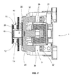
- the switch device 1 illustrated in FIG. 1 is an electromagnetic contactor comprising a plurality of double-break power poles.
- Each power pole comprises a movable contact bridge 10 having contact pads 11 and 12 which cooperate with fixed contacts 13 and 14.
- Each contact bridge 10 is mounted in a central receiving housing 21 provided in the body 20.
- the movable contact bridges 10 are displaced by the translational movement of the movable contact carrier 2 which is actuated by means of an electromagnet 3.
- the electromagnet 3 comprises a coil 31, a fixed armature 32 and a movable armature 30 of the diving type which is subjected to the pressure of a conical spring 37 mounted beneath it, the spring being expanded when said frame is in rest position.
- the attraction of the movable armature 30 towards the fixed armature 32 causes the translational movement of the movable contact holder 2 so as to obtain the closure of the contacts.
- the opening of the contacts is caused by the displacement of the movable armature 30 towards its rest position by means of the spring 37 which passes from a compressed position to a relaxed position.
- the body 20 of the movable contact carrier 2 is extended by two lower parts 22 located on either side of the contact carrier 2 in the direction of the electromagnet 3.
- the movable armature 30 of the electromagnet is fixed to the two lower parts 22 of the movable contact holder 2 by means of snap-type assembly means.
- these assembly means are constituted by at least one resilient locking lug 23.
- each lower portion 22 of the contact carrier 2 has a resilient snap-on lug 23 having each one a hooking notch 24 directed towards the inside of the body 20 as well as, under this hooking catch 24, an oblique internal side panel 24a.
- Each notch 24 also has an upper rim 24b directed towards the body 20.
- the moving armature 30 is an E-shaped laminated mobile magnetic circuit 33 comprising a core 35 having a longitudinal axis X, an orifice 34 of rectangular section pierced in the core 35 transversely to the longitudinal axis X and three branches 36 perpendicular to this core intended to be attracted by the fixed armature 32 during the passage of a current in the coil 31.
- This type of mobile armature is generally used for an electromagnet alternating current.
- the indirect assembly means of the mobile magnetic circuit 33 to the contact carrier 2 are constituted by an intermediate piece, such as a metal key 4, which is necessary since the dimensions of the mobile circuit 33 are not suitable for the spacing. resilient tabs 23.
- This key 4 is of substantially parallelepipedal shape and has two ends 40 in the lengthwise direction. To secure it with the mobile circuit 33, it is inserted elastically into the hole 34 of the core 35. Once inserted, the key 4 has a longitudinal curvature that allows it to maintain a fixed position by leaning on the inner walls of the orifice 34. Finally, the key 4 has a sufficient length to be snap-fit between the two elastic tabs 23, and a small width and a small thickness, so that its two ends 40 can to stay inside the notches 24.
- the movable armature 30 is a magnetic pallet 38 of substantially parallelepipedal shape, commonly used for a DC electromagnet, and which has a flat upper face 38b in the direction of the contact holder 2
- the direct assembly means of the mobile magnetic pallet 38 to the contact carrier 2 are constituted by two lugs 38a located on opposite edges of the pallet 38, provided with a chamfer 38c and intended to be directly snapped into the elastic tabs 23 of the movable contact carrier 2.
- an insulation flange 27 located below the central housings 21 and above the elastic tabs 23 makes it possible to partition the power poles with respect to the movable armature in order to prevent any damage to the armature. electromagnet during a break in the arc at the opening of the contacts.
- positioning means 50 are provided on said flange. These means consist of at least two bosses 51 arranged on the lower face 27a of the flange 27. They are advantageously spaced apart by a distance equivalent to the width of the core 35 of the E-shaped mobile circuit 33 so as to cooperate with the edges of the soul so that it is positioned and fits between these two bosses.
- the magnetic pallet 38 has such a thickness that when assembled with the contact holder 2, it can rest directly against the upper flanges 24b of the notches 24 and against the lower face 27a of the flange 27.
- Means 52 complementary to the means 50 are present on the upper face 38b of the pallet 38. These complementary means 52 may consist of cavities which cooperate with the bosses 51 to position and wedge the pallet 38 against the isolation flange 27.
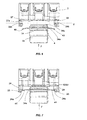
- the mounting of the mobile armature of the electromagnet on the movable contact holder 2 is in the manner of a latching, as shown in Figures 6 and 7.
- the movable armature 30, here the mobile circuit 33 in E shape is brought close to the lower portion 22 of the movable contact holder parallel to the lower face 27a of the flange 27, the key 4 being positioned along an axis Y passing through the two elastic tabs 23.
- the ends 40 of the key 4 are then pressed against the oblique sides 24a of the elastic tabs 23, then by a pushing movement towards the flange along the arrow F, the elastic tabs 23 move outwardly from the body 20 of the movable contact carrier to allow inserting the ends 40 of the key in the notches 24.
- the key 4 comprises, near its ends 40, two orifices 41 in which can come to rest a tool that will be used to exert the thrust movement necessary to snap the movable circuit.
- the orifice 34 of rectangular section, has four internal walls, the upper inner wall 34b representing that being the closest to the isolation flange 27. At its two ends, the orifice 34 forms four edges at right angles to the core 35 of the magnetic circuit 33, the upper edge 34a corresponding to the edge formed by the upper inner wall 34b.
- the key 4 exerts an elastic pressure on the upper inner wall 34b of the orifice 34 contributing to press the movable circuit 33 against the lower face 27a of the flange 27 of the contact carrier 2, between both bosses 51.
- the longitudinal curvature of the key 4 allows it to not be in contact with the upper edges 34a of the orifice 34, which would cause premature wear of the key after a certain number of my parts of the electromagnet of the electromagnetic contactor.
- the assembly proceeds identically when the movable armature of the electromagnet is a pallet 38.
- the chamfers 38c of the two lugs 38a are pressed against the oblique faces 24a, then by a thrust movement of the vane 38 towards the flange along the arrow F, the elastic lugs 23 move outwardly from the body 20 of the door -contacts mobile to allow to insert the lugs 38a of the pallet in the notches 24 of the elastic tabs.
Landscapes
- Physics & Mathematics (AREA)
- Electromagnetism (AREA)
- Electromagnets (AREA)
- Arc-Extinguishing Devices That Are Switches (AREA)
- Breakers (AREA)
Description
- La présente invention concerne un appareil interrupteur électromagnétique comprenant un porte-contacts mobile équipé d'un ensemble de ponts de contacts coopérant avec des contacts fixes, et comprenant un électro-aimant constitué par une bobine, une armature fixe et une armature mobile, l'armature mobile de l'électro-aimant étant associée au porte-contacts et assurant la manoeuvre du porte-contacts en translation de manière à ouvrir ou fermer les contacts.
- Le brevet FR 2518308 décrit un appareil interrupteur électromagnétique du type contacteur comportant un électro-aimant fonctionnant en courant alternatif. Le porte-contacts du contacteur présente une cavité inférieure dans laquelle est logée l'armature mobile de l'électro-aimant, la fixation de l'armature mobile étant réalisée à l'aide d'une goupille traversant l'armature et introduite dans le corps du porte-contacts de chaque côté de la cavité. L'armature mobile de l'électro-aimant est un circuit magnétique en forme de E, couramment utilisé pour un électro-aimant à courant alternatif, et le mode d'assemblage au porte-contacts est par conséquent bien adapté. Cependant, ce mode serait difficile à mettre en oeuvre pour une armature mobile du type à palette utilisée plutôt pour un électro-aimant à courant continu, la palette étant en effet de trop faible épaisseur pour la traversée d'une telle goupille.
- Le brevet US 5281937 décrit un appareil interrupteur électromagnétique du type contacteur comprenant une armature mobile d'un électro-aimant constituée d'une palette plane, dont la forme est adaptée pour qu'elle puisse se fixer au porte-contacts mobile du contacteur, à l'aide de pattes élastiques d'encliquetage disposées sur ce porte-contacts. Ce mode de fixation n'est cependant pas directement adaptable à une armature mobile constitué d'un circuit magnétique en forme de E.
- L'invention a donc pour objet un appareil interrupteur électromagnétique dont les différents types d'armatures mobiles d'électro-aimants (notamment à courant continu ou à courant alternatif) peuvent s'assembler avec un même porte-contacts mobile, l'association étant avantageusement réalisée de manière rapide, permettant ainsi de réduire considérablement le nombre de pièces différentes nécessaires à la fabrication de toute une gamme de contacteurs.
- Conformément à l'invention, l'appareil interrupteur comprend un porte-contacts mobile équipé d'un ensemble de ponts de contacts et comprend un électro-aimant constitué par une bobine, une armature fixe et une armature mobile. Cette armature mobile est assemblée par encliquetage au porte-contacts mobile par des moyens d'assemblage adaptés pour permettre aussi bien un assemblage direct qu'un assemblage indirect. Sur le porte-contacts mobile, les moyens d'assemblage comportent, au moins une patte élastique d'encliquetage. Par exemple, l'assemblage est direct quand l'armature mobile de l'électro-aimant est une palette magnétique comprenant des moyens d'assemblage direct qui sont constitués par deux ergots de la palette directement encliquetables dans les pattes élastiques du porte-contacts mobile. L'assemblage est indirect quand l'armature mobile de l'électro-aimant est par exemple un circuit magnétique mobile comprenant des moyens d'assemblage indirect qui sont constitués par une pièce intermédiaire, solidarisée avec ce circuit magnétique et encliquetable dans les pattes élastiques du porte-contacts mobile.
- D'autres caractéristiques apparaîtront à la lecture de la description qui va suivre et en regard des dessins annexés, parmi lesquels :
- la figure 1 est une vue en coupe de l'appareil interrupteur électromagnétique conforme à l'invention;
- la figure 2 est une vue en perspective du porte-contacts mobile de l'appareil associé à un premier type d'armature mobile d'un électro-aimant;
- la figure 3 est une vue en coupe de l'association de la figure 2;
- la figure 4 reprend la figure 2 avec un second type d'armature mobile;
- la figure 5 est une vue en coupe de l'association de la figure 4;
- les figures 6 et 7 illustrent l'assemblage du porte-contacts et de l'armature mobile de la figure 2.
- L'appareil interrupteur 1 illustré à la figure 1 est un contacteur électromagnétique comprenant plusieurs pôles de puissance à double coupure.
- Chaque pôle de puissance comprend un pont de contacts mobiles 10 doté de pastilles de contacts 11 et 12 qui coopèrent avec des contacts fixes 13 et 14. Chaque pont de contacts 10 est monté dans un logement central d'accueil 21 prévu dans le corps 20 d'un porte-contacts mobile 2. Les ponts de contacts mobiles 10 sont déplacés par la manoeuvre en translation du porte-contacts mobile 2 qui est actionné au moyen d'un électro-aimant 3.
- Dans la figure 1, l'électro-aimant 3 comprend une bobine 31, une armature fixe 32 et une armature mobile 30 du genre plongeante qui est soumise à la pression d'un ressort conique 37 monté sous elle, le ressort étant détendu lorsque ladite armature est en position de repos. L'attraction de l'armature mobile 30 vers l'armature fixe 32 provoque le déplacement en translation du porte-contacts mobile 2 de manière à obtenir la fermeture des contacts. L'ouverture des contacts est provoquée par le déplacement de l'armature mobile 30 vers sa position de repos au moyen du ressort 37 qui passe d'une position comprimée à une position détendue.
- Le corps 20 du porte-contacts mobile 2 est prolongé par deux parties inférieures 22 situées de part et d'autre du porte-contacts 2 en direction de l'électro-aimant 3. L'armature mobile 30 de l'électro-aimant est fixée aux deux parties inférieures 22 du porte-contacts mobile 2 grâce à des moyens d'assemblage du type à encliquetage. Sur le porte-contacts 2, ces moyens d'assemblage sont constitués par au moins une patte élastique d'encliquetage 23. Suivant un mode de réalisation préféré, chaque partie inférieure 22 du porte-contacts 2 possède une patte élastique d'encliquetage 23 présentant chacune un cran d'accrochage 24 dirigé vers l'intérieur du corps 20 ainsi que, sous ce cran d'accrochage 24, un pan latéral interne 24a oblique. Chaque cran 24 comporte également un rebord supérieur 24b dirigé vers le corps 20.
- Dans l'exemple illustré en figure 2, l'armature mobile 30 est un circuit magnétique mobile feuilleté 33, en forme de E, comportant une âme 35 d'axe longitudinal X, un orifice 34 de section rectangulaire percé dans l'âme 35 transversalement à l'axe longitudinal X et trois branches 36 perpendiculaires à cet âme destinées à être attirées par l'armature fixe 32 lors du passage d'un courant dans la bobine 31. Ce type d'armature mobile est généralement utilisée pour un électro-aimant à courant alternatif.
- Les moyens d'assemblage indirect du circuit magnétique mobile 33 au porte-contacts 2 sont constitués par une pièce intermédiaire, tels qu'une clavette métallique 4, qui est nécessaire vu que les dimensions du circuit mobile 33 ne sont pas adaptées à l'écartement des pattes élastiques 23. Cette clavette 4 est de forme sensiblement parallélépipédique et possède deux extrémités 40 dans le sens de la longueur. Pour la solidariser avec le circuit mobile 33, elle est insérée de façon élastique dans l'orifice 34 de l'âme 35. Une fois insérée, la clavette 4 présente une courbure longitudinale qui lui permet de se maintenir en position fixe en s'appuyant sur les parois internes de l'orifice 34. Enfin, la clavette 4 a une longueur suffisante pour être encliquetable entre les deux pattes élastiques 23, ainsi qu'une faible largeur et une faible épaisseur, de façon à ce que ses deux extrémités 40 puissent se loger à l'intérieur des crans 24.
- Dans l'exemple illustré en figure 4, l'armature mobile 30 est une palette magnétique 38 de forme sensiblement parallélépipédique, couramment utilisée pour un électro-aimant à courant continu, et qui comporte une face supérieure plane 38b en direction du porte-contacts 2. Les moyens d'assemblage direct de la palette magnétique mobile 38 au porte-contacts 2 sont constitués par deux ergots 38a situés sur des arêtes opposées de la palette 38, munis d'un chanfrein 38c et destinés à être directement encliquetés dans les pattes élastiques 23 du porte-contacts mobile 2.
- Par ailleurs, un flasque d'isolement 27 situé en dessous des logements centraux 21 et au-dessus des pattes élastiques 23 permet de cloisonner les pôles de puissance vis-à-vis de l'armature mobile afin d'éviter tout endommagement de l'électro-aimant lors d'une coupure d'arc à l'ouverture des contacts.
- Les dimensions de la partie inférieure 22 du porte-contacts mobile relatives au positionnement des pattes élastiques 23 et du flasque d'isolement 27 sont calculées de façon que l'armature mobile 30 soit plaquée contre une face inférieure 27a dudit flasque pour gagner en encombrement interne de l'appareil. Ainsi, pour conforter la butée de l'armature mobile et son calage contre le flasque d'isolement 27, des moyens de positionnement 50 sont prévus sur ledit flasque. Ces moyens consistent en au moins deux bossages 51 disposés sur la face inférieure 27a du flasque 27. Ils sont avantageusement écartés d'une distance équivalente à la largeur de l'âme 35 du circuit mobile 33 en forme de E de manière à coopérer avec les bords de l'âme pour que celle-ci se positionne et s'emboîte entre ces deux bossages.
- La palette magnétique 38 possède une épaisseur telle qu'une fois assemblée avec le porte-contacts 2, elle puisse reposer directement contre les rebords supérieurs 24b des crans 24 et contre la face inférieure 27a du flasque 27. Des moyens 52 complémentaires aux moyens 50 sont présents sur la face supérieure 38b de la palette 38. Ces moyens complémentaires 52 peuvent être constitués de cavités qui coopèrent avec les bossages 51 pour positionner et caler la palette 38 contre le flasque d'isolement 27.
- Le montage de l'armature mobile de l'électro-aimant sur le porte-contacts mobile 2 se fait à la manière d'un encliquetage, comme illustré aux figures 6 et 7. L'armature mobile 30, ici le circuit mobile 33 en forme de E, est amenée à proximité de la partie inférieure 22 du porte-contacts mobile parallèlement à la face inférieure 27a du flasque 27, la clavette 4 étant positionnée selon un axe Y passant par les deux pattes élastiques 23. Les extrémités 40 de la clavette 4 sont ensuite appuyées contre les pans obliques 24a des pattes élastiques 23, puis par un mouvement de poussée vers le flasque suivant la flèche F, les pattes élastiques 23 s'écartent vers l'extérieur du corps 20 du porte-contacts mobile pour permettre d'insérer les extrémités 40 de la clavette dans les crans 24. Au moment de l'insertion, le fait de relâcher le circuit mobile 33 entraîne le retour en position de repos des pattes élastiques 23, ce qui réalise la retenue de l'armature. Pour faciliter cette opération de montage, la clavette 4 comporte, à proximité de ses extrémités 40, deux orifices 41 dans lesquels peut venir s'appuyer un outil qui servira à exercer le mouvement de poussée nécessaire à l'encliquetage du circuit mobile.
- L'orifice 34, de section rectangulaire, possède quatre parois internes, la paroi interne supérieure 34b représentant celle étant la plus proche du flasque d'isolement 27. A ses deux extrémités, l'orifice 34 forme quatre arêtes à angle droit avec l'âme 35 du circuit magnétique 33, l'arête supérieure 34a correspondant à l'arête formée par la paroi interne supérieure 34b. Une fois l'armature mobile 33 montée sur le porte-contacts mobile 2, la forme de la clavette 4 présente une courbure longitudinale grâce à laquelle elle ne repose que sur trois points d'appui : d'une part les deux extrémités 40 de la clavette 4 reposent sur les rebords supérieurs 24b des crans d'accrochage 24 (voir figures 6 et 7) et d'autre part la partie centrale de la clavette 4 repose sur la paroi interne supérieure 34b de l'orifice 34. Ainsi, en prenant appui sur les rebords supérieurs 24b des crans 24, la clavette 4 exerce une pression élastique sur la paroi interne supérieure 34b de l'orifice 34 contribuant à plaquer le circuit mobile 33 contre la face inférieure 27a du flasque 27 du porte-contacts 2, entre les deux bossages 51. De plus, la courbure longitudinale de la clavette 4 lui permet de ne pas se trouver en contact avec les arêtes supérieures 34a de l'orifice 34, ce qui entraînerait une usure prématurée de cette clavette au bout d'un certain nombre de manoeuvres de l'électro-aimant du contacteur électromagnétique.
- Le montage se déroule de manière identique quand l'armature mobile de l'électro-aimant est une palette 38. Une fois celle-ci amenée à proximité de la partie inférieure 22 du porte-contacts mobile parallèlement à la face inférieure 27a du flasque 27, les chanfreins 38c des deux ergots 38a sont appuyés contre les pans obliques 24a, puis par un mouvement de poussée de la palette 38 vers le flasque suivant la flèche F, les pattes élastiques 23 s'écartent vers l'extérieur du corps 20 du porte-contacts mobile pour permettre d'insérer les ergots 38a de la palette dans les crans 24 des pattes élastiques.
Claims (6)
- Appareil interrupteur électromagnétique comprenant un porte-contacts mobile (2) équipé d'un ensemble de ponts de contacts (10) qui portent des contacts mobiles de puissance (11, 12) coopérant avec des contacts fixes (13, 14), et comprenant un électroaimant (3) doté d'une armature mobile (30) qui comporte un circuit magnétique mobile (33) doté d'une âme longitudinale (35), le porte-contacts mobile (2) comprenant deux pattes élastiques d'encliquetage (23) susceptibles de recevoir des moyens d'assemblage indirect (4, 40),
caractérisé en ce que les moyens d'assemblage indirect comprennent une clavette (4) qui est solidarisée à l'armature mobile (30) par insertion élastique dans un orifice (34) de l'âme (35) du circuit magnétique mobile (33), la clavette (4) comportant deux extrémités (40) encliquetées dans les pattes élastiques (23) du porte-contacts mobile (2) et une partie centrale reposant sur une paroi interne (34b) de l'orifice (34), pour former trois points d'appui. - Appareil interrupteur électromagnétique selon la revendication 1, caractérisé en ce que la clavette (4) présente une courbure longitudinale lui permettant d'exercer une pression élastique pour contribuer au maintien du circuit mobile (33) contre le porte-contacts mobile (2) tout en évitant que la clavette (4) ne se trouve en contact avec des arêtes supérieures (34a) de l'orifice (34).
- Appareil interrupteur électromagnétique selon la revendication 1, caractérisé en ce que le porte-contacts mobile (2) comprend des logements centraux (21) accueillant les ponts de contacts mobiles (10), et un flasque d'isolement (27) muni d'une face inférieure (27a), ce flasque d'isolement (27) étant situé entre les logements centraux (21) et les pattes élastiques (23) de manière à assurer une protection de l'électroaimant (3) lors d'une ouverture des contacts.
- Appareil interrupteur électromagnétique selon la revendication 3, caractérisé en ce que le flasque d'isolement (27) est pourvu de moyens de positionnement (50) sur sa face inférieure (27a) de manière à assurer un calage du circuit mobile (33) contre le flasque,
- Appareil interrupteur électromagnétique selon la revendication 4, caractérisé en ce que les moyens de positionnement (50) sont constitués par au moins deux bossages (51) sur la face inférieure (27a) du flasque d'isolement (27).
- Appareil interrupteur électromagnétique selon la revendication 4, caractérisé en ce que les moyens de positionnement (50) sont écartés d'une distance équivalente à la largeur de l'âme (35) du circuit mobile (33).
Applications Claiming Priority (2)
| Application Number | Priority Date | Filing Date | Title |
|---|---|---|---|
| FR9815184 | 1998-12-01 | ||
| FR9815184 | 1998-12-01 |
Publications (2)
| Publication Number | Publication Date |
|---|---|
| EP1006549A1 EP1006549A1 (fr) | 2000-06-07 |
| EP1006549B1 true EP1006549B1 (fr) | 2006-11-02 |
Family
ID=9533469
Family Applications (1)
| Application Number | Title | Priority Date | Filing Date |
|---|---|---|---|
| EP99402973A Expired - Lifetime EP1006549B1 (fr) | 1998-12-01 | 1999-11-29 | Appareil interrupteur électromagnétique |
Country Status (6)
| Country | Link |
|---|---|
| US (1) | US6239679B1 (fr) |
| EP (1) | EP1006549B1 (fr) |
| DE (1) | DE69933842T2 (fr) |
| ES (1) | ES2275333T3 (fr) |
| UA (1) | UA61989C2 (fr) |
| ZA (1) | ZA200003868B (fr) |
Families Citing this family (4)
| Publication number | Priority date | Publication date | Assignee | Title |
|---|---|---|---|---|
| JP3802998B2 (ja) * | 1999-07-26 | 2006-08-02 | 株式会社東海理化電機製作所 | ロータリスイッチ |
| JP5029731B2 (ja) * | 2010-07-08 | 2012-09-19 | 富士電機機器制御株式会社 | 電磁接触器 |
| KR102204849B1 (ko) * | 2014-05-20 | 2021-01-18 | 후지 덴키 기기세이교 가부시끼가이샤 | 전자 접촉기 |
| CN106128860B (zh) * | 2016-07-24 | 2018-06-26 | 贵州天义电器有限责任公司 | 一种具有多路辅助触点的三相交流接触器 |
Family Cites Families (5)
| Publication number | Priority date | Publication date | Assignee | Title |
|---|---|---|---|---|
| US3824509A (en) * | 1972-05-17 | 1974-07-16 | Furnas Electric Co | Magnetically operated electric switch device |
| DE7402795U (de) * | 1974-01-28 | 1974-04-25 | Bbc Ag | Elektromagnetisches Schütz |
| US5281937A (en) * | 1992-07-14 | 1994-01-25 | Fasco Industries, Inc. | Electromagnetic contactor and method for making same |
| FR2737603A1 (fr) * | 1995-08-04 | 1997-02-07 | Schneider Electric Sa | Appareil contacteur |
| DE19648053C1 (de) * | 1996-11-20 | 1998-03-12 | Siemens Ag | Elektromagnetisches Schaltgerät |
-
1999
- 1999-01-12 UA UA2000085079A patent/UA61989C2/uk unknown
- 1999-11-29 ES ES99402973T patent/ES2275333T3/es not_active Expired - Lifetime
- 1999-11-29 DE DE69933842T patent/DE69933842T2/de not_active Expired - Lifetime
- 1999-11-29 EP EP99402973A patent/EP1006549B1/fr not_active Expired - Lifetime
- 1999-12-01 US US09/451,772 patent/US6239679B1/en not_active Expired - Lifetime
-
2000
- 2000-07-31 ZA ZA200003868A patent/ZA200003868B/xx unknown
Also Published As
| Publication number | Publication date |
|---|---|
| ES2275333T3 (es) | 2007-06-01 |
| US6239679B1 (en) | 2001-05-29 |
| UA61989C2 (en) | 2003-12-15 |
| DE69933842D1 (de) | 2006-12-14 |
| EP1006549A1 (fr) | 2000-06-07 |
| DE69933842T2 (de) | 2007-03-01 |
| ZA200003868B (en) | 2001-06-01 |
Similar Documents
| Publication | Publication Date | Title |
|---|---|---|
| EP2936534B1 (fr) | Dispositif modulaire de commutation électrique comportant au moins un bloc de coupure unipolaire et ensemble de commutation comportant de tels dispositifs | |
| FR2622350A1 (fr) | Borne pour disjoncteur pouvant etre installee sur les lieux d'utilisation | |
| WO2014096580A1 (fr) | Dispositif modulaire de commutation électrique comportant au moins un bloc de coupure unipolaire et ensemble de commutation comportant de tels dispositifs | |
| FR3047120B1 (fr) | Boitier de connection electrique et faisceau de cablage | |
| EP1243011B1 (fr) | Contacteur a masque frontal | |
| EP3206260A1 (fr) | Appareil électrique ayant une borne de connexion à pression avec une agrafe de support guidant et limitant la déformation élastique du ressort de contact | |
| FR3010839A1 (fr) | Dispositif de raccordement electrique d'au moins un conducteur dans une borne appartenant a un appareil electrique | |
| EP3487006A1 (fr) | Système électrique comprenant un appareil électrique et un module de connexion interchangeable | |
| EP0086698B1 (fr) | Petit contacteur équipé d'un sous-ensemble amovible d'interrupteurs auxiliaires | |
| EP1006549A1 (fr) | Appareil interrupteur électromagnétique | |
| EP1100105B1 (fr) | Dispositif de précâblage pour contacteurs | |
| EP3598582B1 (fr) | Dispositif de connexion électrique | |
| EP2936536B1 (fr) | Dispositif modulaire de commutation électrique comportant au moins un bloc de coupure unipolaire et ensemble de commutation comportant de tels dispositifs | |
| EP0860901B1 (fr) | Boítier pour appareillage électrique et appareil électrique comportant un tel boítier | |
| EP4186084B1 (fr) | Chambre de coupure d'arc electrique pour appareil electrique de protection et appareil electrique de protection comprenant au moins une telle chambre de coupure | |
| EP0552114B1 (fr) | Borne de raccordement multiple pour appareillage électrique modulaire | |
| EP0994529A1 (fr) | Connecteur avec fiche et embase à faible force d'insertion, notamment du type à contacts broche/lyre | |
| EP0975057A1 (fr) | "Piece de contact pour connecteur femelle, et connecteur comportant une telle piece de contact" | |
| WO2002021550A1 (fr) | Dispositif de coupure d'un appareil interrupteur | |
| EP2469672B1 (fr) | Dispositif de fixation d'un module de raccordement électrique par encliquetage sur un rail ou un support percé | |
| EP0076183B1 (fr) | Dispositif de distribution électrique | |
| EP0108022B1 (fr) | Disjoncteur à sectionnement de neutre | |
| FR2877504A1 (fr) | Connecteur electrique a interference de formes. | |
| WO2007031681A1 (fr) | Contacteur de demarreur de moteur thermique comportant des moyens perfectionnes de raccordement electrique de son bobinage | |
| FR2576141A1 (fr) | Disjoncteur basse tension, avec verrou de maintien agence dans une chambre separee |
Legal Events
| Date | Code | Title | Description |
|---|---|---|---|
| PUAI | Public reference made under article 153(3) epc to a published international application that has entered the european phase |
Free format text: ORIGINAL CODE: 0009012 |
|
| 17P | Request for examination filed |
Effective date: 19991229 |
|
| AK | Designated contracting states |
Kind code of ref document: A1 Designated state(s): DE ES FR GB IT |
|
| AX | Request for extension of the european patent |
Free format text: AL;LT;LV;MK;RO;SI |
|
| AKX | Designation fees paid |
Free format text: DE ES FR GB IT |
|
| RAP1 | Party data changed (applicant data changed or rights of an application transferred) |
Owner name: SCHNEIDER ELECTRONIC INDUSTRIES SAS |
|
| RAP1 | Party data changed (applicant data changed or rights of an application transferred) |
Owner name: SCHNEIDER ELECTRIC INDUSTRIES SAS |
|
| 17Q | First examination report despatched |
Effective date: 20050705 |
|
| GRAP | Despatch of communication of intention to grant a patent |
Free format text: ORIGINAL CODE: EPIDOSNIGR1 |
|
| GRAS | Grant fee paid |
Free format text: ORIGINAL CODE: EPIDOSNIGR3 |
|
| GRAA | (expected) grant |
Free format text: ORIGINAL CODE: 0009210 |
|
| AK | Designated contracting states |
Kind code of ref document: B1 Designated state(s): DE ES FR GB IT |
|
| REG | Reference to a national code |
Ref country code: GB Ref legal event code: FG4D Free format text: NOT ENGLISH |
|
| GBT | Gb: translation of ep patent filed (gb section 77(6)(a)/1977) |
Effective date: 20061122 |
|
| REF | Corresponds to: |
Ref document number: 69933842 Country of ref document: DE Date of ref document: 20061214 Kind code of ref document: P |
|
| REG | Reference to a national code |
Ref country code: ES Ref legal event code: FG2A Ref document number: 2275333 Country of ref document: ES Kind code of ref document: T3 |
|
| PLBE | No opposition filed within time limit |
Free format text: ORIGINAL CODE: 0009261 |
|
| STAA | Information on the status of an ep patent application or granted ep patent |
Free format text: STATUS: NO OPPOSITION FILED WITHIN TIME LIMIT |
|
| 26N | No opposition filed |
Effective date: 20070803 |
|
| REG | Reference to a national code |
Ref country code: FR Ref legal event code: PLFP Year of fee payment: 18 |
|
| REG | Reference to a national code |
Ref country code: FR Ref legal event code: PLFP Year of fee payment: 19 |
|
| PGFP | Annual fee paid to national office [announced via postgrant information from national office to epo] |
Ref country code: FR Payment date: 20171006 Year of fee payment: 19 Ref country code: DE Payment date: 20171005 Year of fee payment: 19 |
|
| PGFP | Annual fee paid to national office [announced via postgrant information from national office to epo] |
Ref country code: ES Payment date: 20171227 Year of fee payment: 19 Ref country code: IT Payment date: 20171115 Year of fee payment: 19 Ref country code: GB Payment date: 20171121 Year of fee payment: 19 |
|
| REG | Reference to a national code |
Ref country code: DE Ref legal event code: R119 Ref document number: 69933842 Country of ref document: DE |
|
| GBPC | Gb: european patent ceased through non-payment of renewal fee |
Effective date: 20181129 |
|
| PG25 | Lapsed in a contracting state [announced via postgrant information from national office to epo] |
Ref country code: DE Free format text: LAPSE BECAUSE OF NON-PAYMENT OF DUE FEES Effective date: 20190601 Ref country code: IT Free format text: LAPSE BECAUSE OF NON-PAYMENT OF DUE FEES Effective date: 20181129 Ref country code: FR Free format text: LAPSE BECAUSE OF NON-PAYMENT OF DUE FEES Effective date: 20181130 |
|
| PG25 | Lapsed in a contracting state [announced via postgrant information from national office to epo] |
Ref country code: GB Free format text: LAPSE BECAUSE OF NON-PAYMENT OF DUE FEES Effective date: 20181129 |
|
| REG | Reference to a national code |
Ref country code: ES Ref legal event code: FD2A Effective date: 20200108 |
|
| PG25 | Lapsed in a contracting state [announced via postgrant information from national office to epo] |
Ref country code: ES Free format text: LAPSE BECAUSE OF NON-PAYMENT OF DUE FEES Effective date: 20181130 |