EP1006602A1 - Batterie mit nichtwässrigem Elektrolyten - Google Patents
Batterie mit nichtwässrigem Elektrolyten Download PDFInfo
- Publication number
- EP1006602A1 EP1006602A1 EP99123522A EP99123522A EP1006602A1 EP 1006602 A1 EP1006602 A1 EP 1006602A1 EP 99123522 A EP99123522 A EP 99123522A EP 99123522 A EP99123522 A EP 99123522A EP 1006602 A1 EP1006602 A1 EP 1006602A1
- Authority
- EP
- European Patent Office
- Prior art keywords
- battery
- battery element
- aqueous electrolyte
- resin layer
- resin
- Prior art date
- Legal status (The legal status is an assumption and is not a legal conclusion. Google has not performed a legal analysis and makes no representation as to the accuracy of the status listed.)
- Granted
Links
Images



Classifications
-
- H—ELECTRICITY
- H01—ELECTRIC ELEMENTS
- H01M—PROCESSES OR MEANS, e.g. BATTERIES, FOR THE DIRECT CONVERSION OF CHEMICAL ENERGY INTO ELECTRICAL ENERGY
- H01M50/00—Constructional details or processes of manufacture of the non-active parts of electrochemical cells other than fuel cells, e.g. hybrid cells
- H01M50/20—Mountings; Secondary casings or frames; Racks, modules or packs; Suspension devices; Shock absorbers; Transport or carrying devices; Holders
-
- H—ELECTRICITY
- H01—ELECTRIC ELEMENTS
- H01M—PROCESSES OR MEANS, e.g. BATTERIES, FOR THE DIRECT CONVERSION OF CHEMICAL ENERGY INTO ELECTRICAL ENERGY
- H01M10/00—Secondary cells; Manufacture thereof
- H01M10/04—Construction or manufacture in general
- H01M10/0431—Cells with wound or folded electrodes
-
- H—ELECTRICITY
- H01—ELECTRIC ELEMENTS
- H01M—PROCESSES OR MEANS, e.g. BATTERIES, FOR THE DIRECT CONVERSION OF CHEMICAL ENERGY INTO ELECTRICAL ENERGY
- H01M10/00—Secondary cells; Manufacture thereof
- H01M10/04—Construction or manufacture in general
- H01M10/0436—Small-sized flat cells or batteries for portable equipment
-
- H—ELECTRICITY
- H01—ELECTRIC ELEMENTS
- H01M—PROCESSES OR MEANS, e.g. BATTERIES, FOR THE DIRECT CONVERSION OF CHEMICAL ENERGY INTO ELECTRICAL ENERGY
- H01M10/00—Secondary cells; Manufacture thereof
- H01M10/05—Accumulators with non-aqueous electrolyte
- H01M10/052—Li-accumulators
- H01M10/0525—Rocking-chair batteries, i.e. batteries with lithium insertion or intercalation in both electrodes; Lithium-ion batteries
-
- H—ELECTRICITY
- H01—ELECTRIC ELEMENTS
- H01M—PROCESSES OR MEANS, e.g. BATTERIES, FOR THE DIRECT CONVERSION OF CHEMICAL ENERGY INTO ELECTRICAL ENERGY
- H01M10/00—Secondary cells; Manufacture thereof
- H01M10/05—Accumulators with non-aqueous electrolyte
- H01M10/056—Accumulators with non-aqueous electrolyte characterised by the materials used as electrolytes, e.g. mixed inorganic/organic electrolytes
- H01M10/0564—Accumulators with non-aqueous electrolyte characterised by the materials used as electrolytes, e.g. mixed inorganic/organic electrolytes the electrolyte being constituted of organic materials only
- H01M10/0565—Polymeric materials, e.g. gel-type or solid-type
-
- H—ELECTRICITY
- H01—ELECTRIC ELEMENTS
- H01M—PROCESSES OR MEANS, e.g. BATTERIES, FOR THE DIRECT CONVERSION OF CHEMICAL ENERGY INTO ELECTRICAL ENERGY
- H01M50/00—Constructional details or processes of manufacture of the non-active parts of electrochemical cells other than fuel cells, e.g. hybrid cells
- H01M50/50—Current conducting connections for cells or batteries
- H01M50/543—Terminals
- H01M50/547—Terminals characterised by the disposition of the terminals on the cells
- H01M50/55—Terminals characterised by the disposition of the terminals on the cells on the same side of the cell
-
- H—ELECTRICITY
- H01—ELECTRIC ELEMENTS
- H01M—PROCESSES OR MEANS, e.g. BATTERIES, FOR THE DIRECT CONVERSION OF CHEMICAL ENERGY INTO ELECTRICAL ENERGY
- H01M50/00—Constructional details or processes of manufacture of the non-active parts of electrochemical cells other than fuel cells, e.g. hybrid cells
- H01M50/50—Current conducting connections for cells or batteries
- H01M50/543—Terminals
- H01M50/552—Terminals characterised by their shape
- H01M50/553—Terminals adapted for prismatic, pouch or rectangular cells
-
- H—ELECTRICITY
- H01—ELECTRIC ELEMENTS
- H01M—PROCESSES OR MEANS, e.g. BATTERIES, FOR THE DIRECT CONVERSION OF CHEMICAL ENERGY INTO ELECTRICAL ENERGY
- H01M50/00—Constructional details or processes of manufacture of the non-active parts of electrochemical cells other than fuel cells, e.g. hybrid cells
- H01M50/50—Current conducting connections for cells or batteries
- H01M50/543—Terminals
- H01M50/562—Terminals characterised by the material
-
- H—ELECTRICITY
- H01—ELECTRIC ELEMENTS
- H01M—PROCESSES OR MEANS, e.g. BATTERIES, FOR THE DIRECT CONVERSION OF CHEMICAL ENERGY INTO ELECTRICAL ENERGY
- H01M6/00—Primary cells; Manufacture thereof
- H01M6/14—Cells with non-aqueous electrolyte
- H01M6/18—Cells with non-aqueous electrolyte with solid electrolyte
- H01M6/181—Cells with non-aqueous electrolyte with solid electrolyte with polymeric electrolytes
-
- Y—GENERAL TAGGING OF NEW TECHNOLOGICAL DEVELOPMENTS; GENERAL TAGGING OF CROSS-SECTIONAL TECHNOLOGIES SPANNING OVER SEVERAL SECTIONS OF THE IPC; TECHNICAL SUBJECTS COVERED BY FORMER USPC CROSS-REFERENCE ART COLLECTIONS [XRACs] AND DIGESTS
- Y02—TECHNOLOGIES OR APPLICATIONS FOR MITIGATION OR ADAPTATION AGAINST CLIMATE CHANGE
- Y02E—REDUCTION OF GREENHOUSE GAS [GHG] EMISSIONS, RELATED TO ENERGY GENERATION, TRANSMISSION OR DISTRIBUTION
- Y02E60/00—Enabling technologies; Technologies with a potential or indirect contribution to GHG emissions mitigation
- Y02E60/10—Energy storage using batteries
-
- Y—GENERAL TAGGING OF NEW TECHNOLOGICAL DEVELOPMENTS; GENERAL TAGGING OF CROSS-SECTIONAL TECHNOLOGIES SPANNING OVER SEVERAL SECTIONS OF THE IPC; TECHNICAL SUBJECTS COVERED BY FORMER USPC CROSS-REFERENCE ART COLLECTIONS [XRACs] AND DIGESTS
- Y02—TECHNOLOGIES OR APPLICATIONS FOR MITIGATION OR ADAPTATION AGAINST CLIMATE CHANGE
- Y02P—CLIMATE CHANGE MITIGATION TECHNOLOGIES IN THE PRODUCTION OR PROCESSING OF GOODS
- Y02P70/00—Climate change mitigation technologies in the production process for final industrial or consumer products
- Y02P70/50—Manufacturing or production processes characterised by the final manufactured product
Definitions
- the present invention relates to a non-aqueous electrolyte battery having a structure that a battery element is accommodated in a casing constituted by a laminate film. More particularly, the present invention relates to improvement in impact resistance of the non-aqueous electrolyte battery.
- batteries in particular, secondary batteries, and more particularly, nonaqueous-electrolyte secondary batteries (so-called "lithium ion batteries”) have energetically be researched and developed to reduce the thickness of the battery and realize a foldable structure.
- the conventional battery incorporating the sealed casing made of metal exhibits a merit that the casing has great rigidity. Therefore, the casing of the battery is not easily deformed. Thus, the electrode elements in the battery can satisfactorily be protected from damage.
- the so-called laminate film suffers from unsatisfactory rigidity. As a result, resistance against external impact is unsatisfactory. Therefore, if the battery is dropped, the electrode element in the battery is susceptible to damage. Thus, there arises a problem in that short circuit easily occurs between the positive electrode and the negative electrode.
- an object of the present invention is to provide a nonaqueous electrolyte battery which is capable of satisfactorily protecting an electrode element therein against external impact and which is enclosed in a laminate film.
- a non-aqueous electrolyte battery comprising: a casing constituted by a laminate film; and a battery element accommodated in the casing and enclosed by welding, wherein a resin layer is formed on one or more surfaces of the battery element so that the battery element and the casing are isolated from each other.
- the non-aqueous electrolyte battery having the above-mentioned structure is able to protect the battery element from external impact owing to the impact buffering function of the resin layer. Therefore, if impact is exerted on the battery in a case of dropping or the like, satisfactory reliability can be realized.
- the nonaqueous electrolyte battery according to the present invention is, for example, a solid electrolyte battery or a gel electrolyte battery.
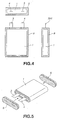
- a battery element 1 having a structure that a solid electrolyte or a gel electrolyte is placed between a positive-electrode active-material layer and a negative-electrode active-material layer is accommodated in a casing 2 constituted by a laminate film. The periphery of the laminate film is welded so that the battery element 1 is enclosed.
- the battery element 1 is provided with a negative-electrode-terminal lead 3 which is electrically connected to a negative electrode, which constitutes the battery element 1, and a positive-electrode-terminal lead 4 which is electrically connected to a positive electrode.
- the negative-electrode-terminal lead 3 and the positive-electrode-terminal lead 4 are extracted to the outside portion of the casing 2.
- the non-aqueous electrolyte battery according to the present invention has a structure that one or more surface between the battery element 1 and the laminate film (the casing 2) is provided with a resin layer.
- resin layers 5 and 6 are disposed on the end surfaces of the wound battery element 1.
- the battery element 1 and the casing 2 constituted by the laminate film are separated from each other.
- the foregoing object can easily be achieved. If the overall surface is covered as described above, the diagonal-line region shown in Fig. 4 becomes a volume loss. Thus, a ratio except for the battery element 1 in the battery case having a limited capacity is undesirably raised. As a result, the volume energy efficiency of the battery undesirably deteriorates.
- the resin is disposed in a limited place, that is, a surface among the surfaces of the battery element 1 having the smallest area.
- a battery of a type according to the present invention and having a structure that a flat battery is packed in a laminate film is sealed while the inside pressure is being lowered in order to remove moisture and improve the airtightness.
- stress which is exerted on the laminate film is concentrated to the corners of the battery. Therefore, the corners of the battery element has a poor durability against impact exerted from outside in a case of, for example, dropping. Therefore, the durability of the battery can be improved if the corners are reliably protected.
- the thickness it is an important fact that the thickness is reduced. If the thickness of a battery having a thickness of 3 mm is reduced by 100 ⁇ m, the volume efficiency deteriorates by 3 %. If the thickness of a battery having a thickness of 0.5 mm is reduced by 100 ⁇ m, the volume efficiency deteriorates by 20 %. Therefore, the structure of the present invention in which the resin layer is formed between the battery element and the laminate film enables the accommodated battery to be protected from external impact owing to the impact buffering function of the resin layer while deterioration in the volume energy efficiency is being minimized.
- a method may be employed with which the battery element 1 is enclosed in the laminate film while resin layers 5 and 6 which have previously been molded and which are constituted by thin resin plates are being inserted, as shown in Fig. 5.
- Another method may be employed which has the steps of applying curing resin to the battery element; curing the resin; and enclosing the battery element into a laminate film. If a laminate film of a type having a space for accommodating a battery therein is employed, the battery element is accommodated in the space. Then, curing resin is enclosed, and then the resin is cured. Then, the laminate film is sealed.
- a resin layer 7 is formed in the periphery of the battery element 1, as shown in Fig. 6.
- the resin layer 7 is constituted by resin layers 7a and 7b which cover the two end surfaces of the battery element 1 and a resin layer 7c formed along the ridges of the battery element 1.
- impact resistance can furthermore be improved.
- each of the resin layers 5, 6 and 7 is not larger than 50 ⁇ m, satisfactory impact resistance cannot be obtained. If the thickness is not smaller than 50 ⁇ m, the impact resistance can somewhat be improved. It is preferable that the thickness is 100 ⁇ m or larger to reliably obtain the foregoing effect and to facilitate the operation. It is preferable that the thickness is about 500 ⁇ m to obtain a required and satisfactory effect. If the thickness is 1 mm or larger, a great loss of the volume efficiency occurs.
- the resin layer disposed between the battery element 1 and the laminate film may be made of at least one type of material selected from a group consisting of polyethylene, polypropylene, polyimide, polyamideimide, polyamide, polyphenylenesulfide, tetrafluoroethylene-perfluoroalkylvinylether copolymer, polyvinylidene fluoride, polytetrafluoroethylene, ethylene fluoride-polypropylene copolymer, ethylene-tetrafluoroethylene copolymer, polyvinyl fluoride, epoxy resin, acrylic resin, methacrylic resin, their mixture resin and crosslinked resin.
- the crosslinked resin is exemplified by 2-hydroxyethyl (meta) acrylate, 2-hydroxypropyl (meta) acrylate, glycerol (meta) acrylate, 2-acrylamide-2-methylpropane sulfonate, sodium sulfonate ethyl (meta) acrylate, (meta) acrylamide, N, N-dimethylaminoethyl (meta) acrylate, N, N-diethylaminoethyl (meta) acrylate, N-isopropylacrylamide, N, N-dimethyl aminopropyl acrylamide, (meta) acrylate, (meta) sodium acrylate, 2-(meta) acryloyloxyethyl succinate, 2-(meta) acryloyl oxyethyl phthalate, 2-(meta) acryloyl oxyethyl hexahydrophthalate, ⁇ -carboxy-polycap
- An initiator which is employed when the ultraviolet-ray curing method is employed is exemplified by any one of the following materials which are activated owing to ultraviolet rays: sulfide, such as sodium methyldithiocarbamate sulfide, tetramethylthiuram monosulfide, diphenyl monosulfide or dibenzothiazoyl monosulfide; thioxanthone derivative, such as thioxanthone, ethylthioxanthone, 2-chlorothioxanthone, diethylthioxanthone or diisopropylthioxanthone; diazo compound, such as hydrazone, azoisobutylonitril or benzenediazonium; an aromatic carbonyl compound, such as benzoin, benzoin methylether, benzoin ethylether, benzoin isopropylether, benzophenone, dimethylaminobenzophenone, Michler'
- a material which is activated owing to a visible ray and which is exemplified as follows may be employed: 2-nitrofluorene, 2, 4, 6-tris (trichloromethyl)-1, 3, 5-triazine, 3, 3'-carbonyl biscoumalin and thio Michler's ketone.
- the foregoing material may be employed solely or two or more types of the materials may be mixed with one another.
- the quantity to be blended is too small, a satisfactory reaction characteristic cannot be realized, the crosslinking point is lowered and plasctization easily takes place. If the quantity is too large, brittleness and decoloration easily occur. Therefore, it is preferable that the quantity is 0.01 part by weight to 20 parts by weight, more previously 0.1 part by weight to 5 parts by weight.
- the light source is an extra-high-pressure mercury lamp, a high-pressure mercury Lamp, a metal halide lamp, a xenone lamp or a low-pressure sterilizing lamp.
- the quantity of the ultraviolet rays to be applied varies depending on the type of the monomer and the amount of the light polymerization initiator. It is preferable that the quantity is 10 mJ/cm 2 to 10 J/cm 2 .
- irradiation with ultraviolet ray may be performed in an atmosphere of an inactive gas or in a state in which the atmosphere is intercepted by glass or a transparent plastic film.
- the polymer material of the solid polymer electrolyte of the battery element 1 may be any one of the following materials: silicon gel, acrylic gel, acrylonitrile gel, polyphosphagen denatured polymer, polyethylene oxide, polypropylene oxide, their composite polymers, crosslinked polymers, denatured polymers or fluorine polymers which are exemplified by poly (vinylidene fluoride), poly (vinylidene fluoride-co-hexafluoropropylene), poly (vinylidene fluoride-co-tetrafluoroethylene), poly (vinylidene fluoride-co-trifluoroethylene) and their mixtures.
- the material is not limited to this.
- the solid electrolyte or the gel electrolyte laminated in the active material layer of the positive electrode or the active material layer of the negative electrode is obtained by causing the active material layer of the positive electrode or the active material layer of the negative electrode to be impregnated with solution composed of a polymer compound, an electrolyte salt and solvent (and a plasticizer in the case of the gel electrolyte). Then, the solvent is removed so that the solution is solidified.
- the active material layer of the positive electrode or the active material layer of the negative electrode is impregnated with a portion of the solid electrolyte or the gel electrolyte laminated in the active material layer of the positive electrode or the active material layer of the negative electrode so as to be solidified.
- the crosslinked material light or heat is used to crosslink the material so as to be solidified.
- the gel electrolyte is composed of a plasticizer containing a lithium salt and 2 wt% to 30 wt% matrix polymer. At this time, ester, ether or carbonate may be employed solely or as a component of the plasticizer.
- a matrix polymer for gelling the carbonate may be any one of a variety of polymers for use to constitute the gel electrolyte. From a viewpoint of stability of oxidation and reduction, it is preferable that a fluorine polymer, such as poly (vinylidene fluoride) or poly (vinylidene fluoride-co-hexafluoropropylene), is employed.
- a fluorine polymer such as poly (vinylidene fluoride) or poly (vinylidene fluoride-co-hexafluoropropylene
- the solid polymer electrolyte is composed of a lithium salt and a polymer compound for dissolving the lithium salt.
- the polymer compound may be ether polymer, such as poly (ethylene oxide) or its crosslinked material, poly (methacrylate) ester, acrylate material, fluorine polymer, such as poly (vinylidene fluoride) or poly (vinylidene fluoride-co-hexafluoropropylene).
- the material may solely be employed or their mixture may be employed. From a viewpoint of stability of oxidation and reduction, it is preferable that a fluorine polymer, such as poly (vinylidene fluoride) or poly (vinylidene fluoride-co-hexafluoropropylene), is employed.
- the lithium salt which is contained in the gel electrolyte or the solid polymer electrolyte may be the lithium salt for use in a usual electrolytic solution for a battery.
- the lithium compound (salt) may be the following materials. Note that the present invention is not limited to the following materials.
- the lithium compound (salt) is exemplified by lithium chloride, lithium bromide, lithium iodide, lithium chlorate, lithium perchlorate, lithium bromate, lithium iodate, lithium nitrate, lithium tetrafluoroborate, lithium hexafluorophosphate, lithium acetate, bis (trifluoromethanesulfonyl) imide lithium.
- the foregoing lithium compound may solely be employed or a plurality of the lithium compounds may be mixed. From a viewpoint of stability of oxidation, it is preferable that LiPF 6 or LiBF 4 is employed.
- concentration of the lithium salt which must be dissolved will now be described.
- 0.1 mol to 3.0 mol may be dissolved in the plasticizer. It is preferable that the concentration is 0.5 mol/litter to 2.0 mol/litter.
- the battery according to the present invention may have a structure of a conventional lithium-ion battery except for the structure that the gel electrolyte or the solid electrolyte is employed.
- the material of the negative electrode of a lithium-ion battery may be a material which permits doping/dedoping of lithium.
- the material for constituting the negative electrode may be non-graphitizing carbon or graphite.
- any one of the following materials may be employed: pyrocarbon, cokes (pitch cokes, needle cokes or petroleum cokes), graphite, vitreous carbon, a sintered material of organic polymer compound (material obtained by baking phenol resin or furan resin at a proper temperature so as to be carbonized), carbon fiber and active carbon.
- a material which permits doping/dedoping lithium polymer, such as polyacetylene or polypyrrole, or an oxide, such as SnO 2 , may be employed.
- a known binder or the like may be added.
- the positive electrode may be constituted by using metal oxide, metal sulphide or specific polymer as the active material of the positive electrode.
- the active material of the positive electrode may be metal sulphide or oxide, such as TiS 2 , MoS 2 , NbSe 2 or V 2 O 5 , which does not contain lithium, or lithium composite oxide mainly composed of Li x Mo 2 (where M is one or more types of transition metal, x varies depending on a state of charge/discharge and it is 0.05 or more and 1.10 or less).
- M is one or more types of transition metal, x varies depending on a state of charge/discharge and it is 0.05 or more and 1.10 or less.
- the transition metal M which constitutes the lithium composite oxide it is preferable that Co, Ni or Mn is employed.
- the lithium composite oxide is exemplified by LiCoO 2 , LiNiO 2 , LiNi y Co 1-y O 2 (where 0 ⁇ y ⁇ 1) and LiMn 2 O 4 .
- the foregoing lithium composite oxide is an excellent active material of the positive electrode which is capable of generating high voltage and which exhibits a satisfactory energy density.
- the positive electrode may be constituted by combining a plurality of types of the foregoing active materials of the positive electrode.
- a known conductive material and a binder may be added.
- the electrode terminals (the negative-electrode-terminal lead 3 and the positive-electrode-terminal lead 4) are joined to collectors of the corresponding positive electrode and the negative electrode. It is preferable that the material of the electrode terminals is an alloy, such as aluminum or titanium, which is not dissolved at a high potential.
- the negative electrode may be made of copper, nickel or their alloy.
- the electrode terminals are bent to be flush with the main surface of the battery element 1 at the end of the wound battery element 1 from a viewpoint of improving the volume efficiency and easily extracting the electrode terminals.
- the resin layers 5, 6 and 7 are effective layers for preventing short circuit and also serving as shock absorbers.
- the non-aqueous electrolyte battery according to the present invention may be a primary battery or a secondary battery. It is most preferable that the non-aqueous electrolyte battery is a lithium-ion secondary battery incorporating the solid electrolyte or the gel electrolyte.
- the negative electrode was manufactured as follows.
- Powder of pulverized graphite in a quantity of 90 parts by weight and 10 parts by weight of poly (vinylidene fluoride-co-hexafluoropropylene) were mixed so that a mix for the negative electrode was prepared. Then, the foregoing mix was dispersed in N-methyl-2-pyrolidone so that slurry was prepared. The foregoing slurry was uniformly applied to either surface of an elongated copper foil which was a collector for the negative electrode and having a thickness of 10 ⁇ m. Then, the wet surface was dried, followed by compression-molding the elongated copper foil by a roll pressing machine. Thus, a negative electrode was manufactured.
- the positive electrode was manufactured as follows.
- LiCoO 2 lithium carbonate and cobalt carbonate were mixed at a molar ratio of 0.5:1, and then the mixed materials were baked at 900°C for 5 hours in air. Then, 91 parts by weight of obtained LiCoO 2 , 6 parts by weight of graphite serving as a conductive material and 10 parts by weight of poly (vinylidene fluoride-co-hexafluoropropylene) serving as the binder were mixed with one another. Thus, a mix for the positive electrode was prepared. Then, the mix was dispersed in N-methyl-2-pyrolidone so that slurry was prepared.
- the foregoing slurry was uniformly applied to either surface of an elongated aluminum foil which was a collector for the positive electrode and having a thickness of 20 ⁇ m. Then, the wet surface was dried, followed by compression-molding the elongated aluminum foil by a roll pressing machine. Thus, a positive electrode was manufactured.
- the gel electrolyte was obtained as follows.
- each of the negative and positive electrodes was uniformly coated with solution prepared by mixing and dissolving 10 parts by weight of poly (vinylidene fluoride-co-hexafluoropropylene) having a weight average molecular weight of 600,000 and 60 parts by weight of diethyl carbonate in 30 parts by weight of plasticizer composed of 42.5 parts by weight of ethylene carbonate (EC), 42.5 parts by weight of propylene carbonate (PC) and 15 parts by weight of LiPF 6 .
- plasticizer composed of 42.5 parts by weight of ethylene carbonate (EC), 42.5 parts by weight of propylene carbonate (PC) and 15 parts by weight of LiPF 6 .
- a positive-electrode-terminal lead made of aluminum and a negative-electrode-terminal lead made of nickel were welded to the surface of the portion of the pole plate on which the active material was not applied. Then, the manufactured structure was encapsulated in a pack constituted by a laminate film. A potion of the pack having a width of 5 mm was welded at 200°C for 10 seconds by a sealing machine so that test batteries were manufactured.
- a resin plate made of polypropylene and having a thickness of 300 ⁇ m was located as shown in Fig. 5, and the resin plate was packed as shown in Figs. 1 and 2. Thus, a test battery was manufactured.
- a resin plate made of polyimide and having a thickness of 300 ⁇ m was located as shown in Fig. 5, and the resin plate was packed as shown in Figs. 1 and 2. Thus, a test battery was manufactured.
- NK Ester 1206PE (trade name of Shin-Nakamura) in a quantity of 40 parts by weight
- NK Ester 9G trade name of Shin-Nakamura
- a curing material (1173" which was a trade name of Ciba-Geigy Co., Ltd.) in a quantity of 0.5 part by weight
- the battery element was accommodated in a laminate film having a space for accommodating the battery in one side thereof. Then, the foregoing resin was enclosed in a clearance portion opposite to the surface adjacent to the electrode terminal and having a thickness of 300 ⁇ m. Then, the high-pressure mercury lamp was turned on to apply ultraviolet rays having energy of 20 mJ/cm 2 for one minute. Thus, a resin layer was formed between the battery element and the laminate film.
- a battery was manufactured by packing only the battery electrode such that the resin layer was not enclosed.
- each sample was initially charged/discharged at a five-hour ratio (1/5 C) of the theoretical capacity, and then each sample was charged/discharged at a two-hour ratio (1/2C) of the theoretical capacity.
- the capacity and average discharge voltage were measured.
- the volume energy density was calculated.
- Samples 1 to 3 each having the resin layer had a satisfactory volume energy density and excellent impact resistance.
- Sample 5 which was a comparative example resulted in unsatisfactory impact resistance and a significant difference in the rate of occurrence of short circuits.
- Sample 4 having the thin resin layer encountered occurrence of short circuit.
- the present invention is able to significantly improve the impact resistance while enclosure with excellent airtightness is being performed. Therefore, the non-aqueous electrolyte battery having satisfactory reliability can be provided if impact is exerted on the battery owing to dropping or the like.
Landscapes
- Chemical & Material Sciences (AREA)
- Chemical Kinetics & Catalysis (AREA)
- Electrochemistry (AREA)
- General Chemical & Material Sciences (AREA)
- Engineering & Computer Science (AREA)
- Manufacturing & Machinery (AREA)
- Condensed Matter Physics & Semiconductors (AREA)
- Dispersion Chemistry (AREA)
- General Physics & Mathematics (AREA)
- Inorganic Chemistry (AREA)
- Physics & Mathematics (AREA)
- Materials Engineering (AREA)
- Secondary Cells (AREA)
- Sealing Battery Cases Or Jackets (AREA)
- Primary Cells (AREA)
Applications Claiming Priority (2)
| Application Number | Priority Date | Filing Date | Title |
|---|---|---|---|
| JP34071998 | 1998-11-30 | ||
| JP34071998A JP3900507B2 (ja) | 1998-11-30 | 1998-11-30 | 非水電解質電池 |
Publications (2)
| Publication Number | Publication Date |
|---|---|
| EP1006602A1 true EP1006602A1 (de) | 2000-06-07 |
| EP1006602B1 EP1006602B1 (de) | 2005-04-27 |
Family
ID=18339668
Family Applications (1)
| Application Number | Title | Priority Date | Filing Date |
|---|---|---|---|
| EP99123522A Expired - Lifetime EP1006602B1 (de) | 1998-11-30 | 1999-11-25 | Batterie mit nichtwässrigem Elektrolyten |
Country Status (7)
| Country | Link |
|---|---|
| US (1) | US6428934B1 (de) |
| EP (1) | EP1006602B1 (de) |
| JP (1) | JP3900507B2 (de) |
| KR (1) | KR100724658B1 (de) |
| CN (1) | CN1166024C (de) |
| DE (1) | DE69924948T2 (de) |
| TW (1) | TW431015B (de) |
Cited By (3)
| Publication number | Priority date | Publication date | Assignee | Title |
|---|---|---|---|---|
| EP2333891A1 (de) * | 2009-11-16 | 2011-06-15 | Samsung SDI Co., Ltd | Sekundärbatterie |
| EP4418424A4 (de) * | 2021-10-13 | 2025-10-01 | Kurita Water Ind Ltd | Transportbehälter für energiespeichervorrichtung und verfahren zum transport einer energiespeichervorrichtung damit |
| EP4318514A4 (de) * | 2021-03-23 | 2025-10-01 | Kurita Water Ind Ltd | Energiespeichervorrichtungsstruktur |
Families Citing this family (35)
| Publication number | Priority date | Publication date | Assignee | Title |
|---|---|---|---|---|
| CN1288594A (zh) * | 1998-11-06 | 2001-03-21 | 日本电池株式会社 | 非水二次电解质电池 |
| CN1197190C (zh) * | 2000-01-27 | 2005-04-13 | 索尼株式会社 | 凝胶电解液电池的制造方法 |
| JP2001266941A (ja) * | 2000-03-17 | 2001-09-28 | Sony Corp | ゲル電解質電池の製造方法 |
| US6682853B2 (en) * | 2000-03-06 | 2004-01-27 | Sony Corporation | Nonaqueous electrolyte secondary battery and method of manufacturing the same |
| DE10020031C2 (de) * | 2000-04-22 | 2002-05-29 | Franz W Winterberg | Verfahren zur Herstellung von wiederaufladbaren Lithium-Polymer-Batterien |
| KR100382069B1 (ko) * | 2000-09-05 | 2003-04-26 | 삼성에스디아이 주식회사 | 리튬 2차 전지의 제조방법 |
| JP4826686B2 (ja) * | 2001-01-29 | 2011-11-30 | 株式会社Gsユアサ | 組電池 |
| US7179562B2 (en) * | 2003-02-14 | 2007-02-20 | Quallion Llc | Battery electrode assembly and fabrication method therefor |
| JP4502616B2 (ja) * | 2003-09-30 | 2010-07-14 | 三洋電機株式会社 | フィルム状外装体を有する電池 |
| CN1879246A (zh) * | 2003-11-05 | 2006-12-13 | 株式会社杰士汤浅 | 电池 |
| JP4679104B2 (ja) * | 2004-09-30 | 2011-04-27 | 三洋電機株式会社 | 非水電解質二次電池とその製造方法 |
| JP4867158B2 (ja) * | 2004-11-19 | 2012-02-01 | トヨタ自動車株式会社 | フィルム外装型蓄電装置 |
| KR100873309B1 (ko) * | 2006-07-10 | 2008-12-12 | 주식회사 엘지화학 | 외부충격에 대해 우수한 안전성을 제공하는 이차전지용안전부재 |
| KR100877811B1 (ko) * | 2006-07-28 | 2009-01-12 | 주식회사 엘지화학 | 양측 하단에 단차가 형성되어 있는 이차전지용 안전부재 |
| KR100824807B1 (ko) | 2006-08-25 | 2008-04-24 | 주식회사 엘티케이 | 리튬 2차전지의 일체형 탭 및 그 제조방법 |
| JP5065646B2 (ja) * | 2006-10-06 | 2012-11-07 | 住友電工ファインポリマー株式会社 | ガスケット、およびリチウムイオン二次電池 |
| JP5094215B2 (ja) * | 2007-05-30 | 2012-12-12 | 三洋電機株式会社 | 電池および組電池 |
| WO2009113470A1 (ja) * | 2008-03-14 | 2009-09-17 | 日本電気株式会社 | 被覆材及びフィルム外装電気デバイス |
| US20100192362A1 (en) * | 2008-09-11 | 2010-08-05 | A123 System, Inc. | Split Charge Forming Process for Battery |
| KR101409692B1 (ko) | 2009-10-30 | 2014-06-19 | 가부시끼가이샤 구레하 | 불화 비닐리덴계 중합체 분말 및 불화 비닐리덴계 중합체 용액 |
| JP5437133B2 (ja) * | 2010-03-31 | 2014-03-12 | 古河電池株式会社 | リチウムイオン電池及びリチウムイオン電池の製造方法 |
| JP5548827B2 (ja) * | 2010-08-09 | 2014-07-16 | エルジー・ケム・リミテッド | 安全性が向上した二次バッテリー |
| CN102170019B (zh) * | 2011-03-31 | 2017-02-08 | 东莞新能源电子科技有限公司 | 软包装锂离子电池 |
| CN102709581A (zh) * | 2012-04-19 | 2012-10-03 | 珠海格力新能源科技有限公司 | 一种提高超薄电池抗褶皱能力的方法 |
| KR20150010481A (ko) | 2013-07-19 | 2015-01-28 | 삼성에스디아이 주식회사 | 파우치 전지 및 그의 제조 방법 |
| EP3132486B1 (de) * | 2014-04-17 | 2018-06-06 | Gotion, Inc. | Alkylbenzoatderivate als elektrolytzusatz für lithiumbasierte batterien |
| KR102221804B1 (ko) * | 2014-07-02 | 2021-03-02 | 삼성에스디아이 주식회사 | 가요성 이차 전지 |
| JP2018055976A (ja) * | 2016-09-29 | 2018-04-05 | 昭和電工パッケージング株式会社 | 包装材及びその製造方法 |
| KR102146540B1 (ko) * | 2017-09-15 | 2020-08-20 | 주식회사 엘지화학 | 배터리 모듈 |
| JP7310096B2 (ja) | 2018-04-10 | 2023-07-19 | ソニーグループ株式会社 | 電池パック及び電子機器 |
| JP7716728B2 (ja) * | 2020-02-06 | 2025-08-01 | エリーパワー株式会社 | 非水電解質二次電池用構造体及びその製造方法並びに非水電解質二次電池の製造方法 |
| CN111430780B (zh) * | 2020-04-28 | 2023-03-28 | 孚能科技(赣州)股份有限公司 | 电解液原料组合物,电解液及锂离子二次电池及其制备方法 |
| JP7273773B2 (ja) * | 2020-10-21 | 2023-05-15 | プライムプラネットエナジー&ソリューションズ株式会社 | ラミネート型蓄電デバイス |
| KR102936714B1 (ko) * | 2022-01-13 | 2026-03-09 | 주식회사 엘지에너지솔루션 | 충격 흡수 기능을 구비한 전지 팩 어셈블리, 이의 제조장치 및 제조방법 |
| KR102875483B1 (ko) * | 2023-03-10 | 2025-10-24 | 삼성에스디아이 주식회사 | 전극조립체 제조 방법 및 이에 의해 제조된 전극조립체 |
Citations (10)
| Publication number | Priority date | Publication date | Assignee | Title |
|---|---|---|---|---|
| US4092464A (en) * | 1976-07-19 | 1978-05-30 | P. R. Mallory & Co. Inc. | Flexible cells and batteries formed therefrom |
| JPS60208049A (ja) * | 1984-04-02 | 1985-10-19 | Matsushita Electric Ind Co Ltd | 密閉形蓄電池 |
| JPS6261268A (ja) * | 1985-09-10 | 1987-03-17 | Toppan Printing Co Ltd | 偏平型電気化学セル |
| JPH01248480A (ja) * | 1988-03-30 | 1989-10-04 | Matsushita Electric Ind Co Ltd | 密閉形鉛蓄電池 |
| JPH0221557A (ja) * | 1988-07-11 | 1990-01-24 | Ricoh Co Ltd | 薄型電池 |
| EP0390557A2 (de) * | 1989-03-30 | 1990-10-03 | Mhb Joint Venture | Batteriezusammenbau und Verfahren zu seiner Herstellung |
| JPH09120812A (ja) * | 1995-10-27 | 1997-05-06 | Fuji Elelctrochem Co Ltd | 集合電池 |
| US5670272A (en) * | 1994-03-31 | 1997-09-23 | Valence Technology, Inc. | Battery packaging for flat cell batteries having a compressing material for the cell stack |
| JPH09259897A (ja) * | 1996-03-19 | 1997-10-03 | Yuasa Corp | 積層電池 |
| EP0834934A1 (de) * | 1996-04-23 | 1998-04-08 | Sumitomo Electric Industries, Ltd. | Nichtwässrige elektrolytische zelle |
Family Cites Families (5)
| Publication number | Priority date | Publication date | Assignee | Title |
|---|---|---|---|---|
| US4997732A (en) * | 1989-03-30 | 1991-03-05 | Mhb Joint Venture | Battery in a vacuum sealed enveloping material and a process for making the same |
| US4925751A (en) * | 1989-04-26 | 1990-05-15 | Shackle Dale R | High power solid state electrochemical laminar cell |
| US5558957A (en) * | 1994-10-26 | 1996-09-24 | International Business Machines Corporation | Method for making a thin flexible primary battery for microelectronics applications |
| JPH10214606A (ja) * | 1996-11-28 | 1998-08-11 | Sanyo Electric Co Ltd | ラミネート外装体の薄型電池 |
| US6083640A (en) * | 1998-09-22 | 2000-07-04 | Samsung Display Device Co., Ltd. | Secondary battery with electrode assembly fixing device |
-
1998
- 1998-11-30 JP JP34071998A patent/JP3900507B2/ja not_active Expired - Lifetime
-
1999
- 1999-11-24 US US09/448,587 patent/US6428934B1/en not_active Expired - Lifetime
- 1999-11-25 DE DE69924948T patent/DE69924948T2/de not_active Expired - Lifetime
- 1999-11-25 EP EP99123522A patent/EP1006602B1/de not_active Expired - Lifetime
- 1999-11-26 TW TW088120733A patent/TW431015B/zh not_active IP Right Cessation
- 1999-11-29 KR KR1019990053379A patent/KR100724658B1/ko not_active Expired - Lifetime
- 1999-11-30 CN CNB991228030A patent/CN1166024C/zh not_active Expired - Lifetime
Patent Citations (10)
| Publication number | Priority date | Publication date | Assignee | Title |
|---|---|---|---|---|
| US4092464A (en) * | 1976-07-19 | 1978-05-30 | P. R. Mallory & Co. Inc. | Flexible cells and batteries formed therefrom |
| JPS60208049A (ja) * | 1984-04-02 | 1985-10-19 | Matsushita Electric Ind Co Ltd | 密閉形蓄電池 |
| JPS6261268A (ja) * | 1985-09-10 | 1987-03-17 | Toppan Printing Co Ltd | 偏平型電気化学セル |
| JPH01248480A (ja) * | 1988-03-30 | 1989-10-04 | Matsushita Electric Ind Co Ltd | 密閉形鉛蓄電池 |
| JPH0221557A (ja) * | 1988-07-11 | 1990-01-24 | Ricoh Co Ltd | 薄型電池 |
| EP0390557A2 (de) * | 1989-03-30 | 1990-10-03 | Mhb Joint Venture | Batteriezusammenbau und Verfahren zu seiner Herstellung |
| US5670272A (en) * | 1994-03-31 | 1997-09-23 | Valence Technology, Inc. | Battery packaging for flat cell batteries having a compressing material for the cell stack |
| JPH09120812A (ja) * | 1995-10-27 | 1997-05-06 | Fuji Elelctrochem Co Ltd | 集合電池 |
| JPH09259897A (ja) * | 1996-03-19 | 1997-10-03 | Yuasa Corp | 積層電池 |
| EP0834934A1 (de) * | 1996-04-23 | 1998-04-08 | Sumitomo Electric Industries, Ltd. | Nichtwässrige elektrolytische zelle |
Non-Patent Citations (6)
| Title |
|---|
| PATENT ABSTRACTS OF JAPAN vol. 010, no. 054 (E - 385) 4 March 1986 (1986-03-04) * |
| PATENT ABSTRACTS OF JAPAN vol. 011, no. 249 (E - 532) 13 August 1987 (1987-08-13) * |
| PATENT ABSTRACTS OF JAPAN vol. 013, no. 594 (E - 867) 27 December 1989 (1989-12-27) * |
| PATENT ABSTRACTS OF JAPAN vol. 014, no. 163 (E - 0910) 29 March 1990 (1990-03-29) * |
| PATENT ABSTRACTS OF JAPAN vol. 1997, no. 09 30 September 1997 (1997-09-30) * |
| PATENT ABSTRACTS OF JAPAN vol. 1998, no. 02 30 January 1998 (1998-01-30) * |
Cited By (4)
| Publication number | Priority date | Publication date | Assignee | Title |
|---|---|---|---|---|
| EP2333891A1 (de) * | 2009-11-16 | 2011-06-15 | Samsung SDI Co., Ltd | Sekundärbatterie |
| US9099696B2 (en) | 2009-11-16 | 2015-08-04 | Samsung Sdi Co., Ltd. | Secondary battery |
| EP4318514A4 (de) * | 2021-03-23 | 2025-10-01 | Kurita Water Ind Ltd | Energiespeichervorrichtungsstruktur |
| EP4418424A4 (de) * | 2021-10-13 | 2025-10-01 | Kurita Water Ind Ltd | Transportbehälter für energiespeichervorrichtung und verfahren zum transport einer energiespeichervorrichtung damit |
Also Published As
| Publication number | Publication date |
|---|---|
| DE69924948D1 (de) | 2005-06-02 |
| KR100724658B1 (ko) | 2007-06-11 |
| TW431015B (en) | 2001-04-21 |
| US6428934B1 (en) | 2002-08-06 |
| JP2000173641A (ja) | 2000-06-23 |
| EP1006602B1 (de) | 2005-04-27 |
| KR20000035752A (ko) | 2000-06-26 |
| CN1166024C (zh) | 2004-09-08 |
| JP3900507B2 (ja) | 2007-04-04 |
| DE69924948T2 (de) | 2006-02-23 |
| CN1258939A (zh) | 2000-07-05 |
Similar Documents
| Publication | Publication Date | Title |
|---|---|---|
| US6428934B1 (en) | Non-aqueous electrolyte battery | |
| JP4529207B2 (ja) | 非水電解質電池 | |
| US6368744B1 (en) | Nonaqueous electrolyte battery having a casing constituted by a laminate film | |
| US6319630B1 (en) | Laminate film case comprising nonaqueous electrolyte battery and control circuit | |
| KR100742109B1 (ko) | 비수성-전해질 2차 전지 및 그 제조방법 | |
| JP4418134B2 (ja) | 高分子ゲル電解質およびそれを用いてなるリチウム電池 | |
| US7297441B2 (en) | Nonaqueous-electrolyte secondary battery | |
| CN1222055C (zh) | 电池组件及其制造方法 | |
| US6682853B2 (en) | Nonaqueous electrolyte secondary battery and method of manufacturing the same | |
| US7387852B2 (en) | Polymer electrolyte and lithium battery using the same | |
| US7767350B2 (en) | Nonaqueous electrolyte battery | |
| US6511769B1 (en) | Electrolyte for rechargeable lithium battery | |
| CN1411616A (zh) | 聚合物凝胶电解质 | |
| EP2804233A1 (de) | Nicht-wässrige Elektrolyt-Sekundärbatterie | |
| JP2002245994A (ja) | リチウム二次電池用収容部材及びそれを用いた二次電池パック | |
| JP3292220B2 (ja) | リチウム電池 | |
| US20030152836A1 (en) | Nonaqueous electrolyte secondary cell | |
| JP2002158034A (ja) | 非水二次電池 | |
| KR200259608Y1 (ko) | 비수성 전해질 전지 | |
| US12586817B2 (en) | Polysulfide-polyoxide electrolyte membrane for energy storage device | |
| JP3474088B2 (ja) | フレキシブル1次リチウム電池 | |
| KR100393043B1 (ko) | 리튬 2차 전지 | |
| MXPA00011789A (en) | Non-aqueous electrolyte battery | |
| JPH09180757A (ja) | 高分子固体電解質電池 |
Legal Events
| Date | Code | Title | Description |
|---|---|---|---|
| PUAI | Public reference made under article 153(3) epc to a published international application that has entered the european phase |
Free format text: ORIGINAL CODE: 0009012 |
|
| AK | Designated contracting states |
Kind code of ref document: A1 Designated state(s): DE FR GB |
|
| AX | Request for extension of the european patent |
Free format text: AL;LT;LV;MK;RO;SI |
|
| 17P | Request for examination filed |
Effective date: 20001109 |
|
| AKX | Designation fees paid |
Free format text: DE FR GB |
|
| 17Q | First examination report despatched |
Effective date: 20040609 |
|
| GRAP | Despatch of communication of intention to grant a patent |
Free format text: ORIGINAL CODE: EPIDOSNIGR1 |
|
| GRAS | Grant fee paid |
Free format text: ORIGINAL CODE: EPIDOSNIGR3 |
|
| GRAA | (expected) grant |
Free format text: ORIGINAL CODE: 0009210 |
|
| AK | Designated contracting states |
Kind code of ref document: B1 Designated state(s): DE FR GB |
|
| REG | Reference to a national code |
Ref country code: GB Ref legal event code: FG4D |
|
| REF | Corresponds to: |
Ref document number: 69924948 Country of ref document: DE Date of ref document: 20050602 Kind code of ref document: P |
|
| PLBE | No opposition filed within time limit |
Free format text: ORIGINAL CODE: 0009261 |
|
| STAA | Information on the status of an ep patent application or granted ep patent |
Free format text: STATUS: NO OPPOSITION FILED WITHIN TIME LIMIT |
|
| ET | Fr: translation filed | ||
| 26N | No opposition filed |
Effective date: 20060130 |
|
| REG | Reference to a national code |
Ref country code: GB Ref legal event code: 746 Effective date: 20091130 |
|
| PGFP | Annual fee paid to national office [announced via postgrant information from national office to epo] |
Ref country code: GB Payment date: 20141119 Year of fee payment: 16 Ref country code: FR Payment date: 20141119 Year of fee payment: 16 |
|
| GBPC | Gb: european patent ceased through non-payment of renewal fee |
Effective date: 20151125 |
|
| REG | Reference to a national code |
Ref country code: FR Ref legal event code: ST Effective date: 20160729 |
|
| PG25 | Lapsed in a contracting state [announced via postgrant information from national office to epo] |
Ref country code: GB Free format text: LAPSE BECAUSE OF NON-PAYMENT OF DUE FEES Effective date: 20151125 |
|
| PG25 | Lapsed in a contracting state [announced via postgrant information from national office to epo] |
Ref country code: FR Free format text: LAPSE BECAUSE OF NON-PAYMENT OF DUE FEES Effective date: 20151130 |
|
| REG | Reference to a national code |
Ref country code: DE Ref legal event code: R082 Ref document number: 69924948 Country of ref document: DE Representative=s name: MUELLER HOFFMANN & PARTNER PATENTANWAELTE MBB, DE Ref country code: DE Ref legal event code: R082 Ref document number: 69924948 Country of ref document: DE Ref country code: DE Ref legal event code: R081 Ref document number: 69924948 Country of ref document: DE Owner name: MURATA MANUFACTURING CO., LTD., NAGAOKAKYO-SHI, JP Free format text: FORMER OWNER: SONY CORPORATION, TOKIO/TOKYO, JP Ref country code: DE Ref legal event code: R081 Ref document number: 69924948 Country of ref document: DE Owner name: MURATA MANUFACTURING CO., LTD., NAGAOKAKYO-SHI, JP Free format text: FORMER OWNER: TOHOKU MURATA MANUFACTURING CO., LTD, KORIYAMA-SHI, JP |
|
| REG | Reference to a national code |
Ref country code: DE Ref legal event code: R082 Ref document number: 69924948 Country of ref document: DE |
|
| PGFP | Annual fee paid to national office [announced via postgrant information from national office to epo] |
Ref country code: DE Payment date: 20181120 Year of fee payment: 20 |
|
| REG | Reference to a national code |
Ref country code: DE Ref legal event code: R071 Ref document number: 69924948 Country of ref document: DE |