EP1006613B1 - Verbesserter Messerkontaktsteckverbinder bestehend aus zwei Teilen - Google Patents
Verbesserter Messerkontaktsteckverbinder bestehend aus zwei Teilen Download PDFInfo
- Publication number
- EP1006613B1 EP1006613B1 EP99309630A EP99309630A EP1006613B1 EP 1006613 B1 EP1006613 B1 EP 1006613B1 EP 99309630 A EP99309630 A EP 99309630A EP 99309630 A EP99309630 A EP 99309630A EP 1006613 B1 EP1006613 B1 EP 1006613B1
- Authority
- EP
- European Patent Office
- Prior art keywords
- contact member
- attachment
- pin
- flattened
- core
- Prior art date
- Legal status (The legal status is an assumption and is not a legal conclusion. Google has not performed a legal analysis and makes no representation as to the accuracy of the status listed.)
- Expired - Lifetime
Links
- 239000004020 conductor Substances 0.000 claims abstract description 25
- 239000002184 metal Substances 0.000 claims abstract description 6
- 238000009413 insulation Methods 0.000 claims description 11
- 238000003780 insertion Methods 0.000 claims description 4
- 230000037431 insertion Effects 0.000 claims description 4
- 230000002708 enhancing effect Effects 0.000 claims description 3
- 239000007787 solid Substances 0.000 claims description 3
- 230000014759 maintenance of location Effects 0.000 description 3
- 238000000034 method Methods 0.000 description 3
- 239000012212 insulator Substances 0.000 description 2
- 238000004519 manufacturing process Methods 0.000 description 2
- 239000000463 material Substances 0.000 description 2
- 229910001369 Brass Inorganic materials 0.000 description 1
- 238000013459 approach Methods 0.000 description 1
- 239000010951 brass Substances 0.000 description 1
- 238000010276 construction Methods 0.000 description 1
- 230000008878 coupling Effects 0.000 description 1
- 238000010168 coupling process Methods 0.000 description 1
- 238000005859 coupling reaction Methods 0.000 description 1
- 239000012528 membrane Substances 0.000 description 1
- 238000012986 modification Methods 0.000 description 1
- 230000004048 modification Effects 0.000 description 1
- 230000000717 retained effect Effects 0.000 description 1
- 238000007789 sealing Methods 0.000 description 1
Images


Classifications
-
- H—ELECTRICITY
- H01—ELECTRIC ELEMENTS
- H01R—ELECTRICALLY-CONDUCTIVE CONNECTIONS; STRUCTURAL ASSOCIATIONS OF A PLURALITY OF MUTUALLY-INSULATED ELECTRICAL CONNECTING ELEMENTS; COUPLING DEVICES; CURRENT COLLECTORS
- H01R4/00—Electrically-conductive connections between two or more conductive members in direct contact, i.e. touching one another; Means for effecting or maintaining such contact; Electrically-conductive connections having two or more spaced connecting locations for conductors and using contact members penetrating insulation
- H01R4/10—Electrically-conductive connections between two or more conductive members in direct contact, i.e. touching one another; Means for effecting or maintaining such contact; Electrically-conductive connections having two or more spaced connecting locations for conductors and using contact members penetrating insulation effected solely by twisting, wrapping, bending, crimping, or other permanent deformation
- H01R4/18—Electrically-conductive connections between two or more conductive members in direct contact, i.e. touching one another; Means for effecting or maintaining such contact; Electrically-conductive connections having two or more spaced connecting locations for conductors and using contact members penetrating insulation effected solely by twisting, wrapping, bending, crimping, or other permanent deformation by crimping
- H01R4/188—Electrically-conductive connections between two or more conductive members in direct contact, i.e. touching one another; Means for effecting or maintaining such contact; Electrically-conductive connections having two or more spaced connecting locations for conductors and using contact members penetrating insulation effected solely by twisting, wrapping, bending, crimping, or other permanent deformation by crimping having an uneven wire-receiving surface to improve the contact
-
- H—ELECTRICITY
- H01—ELECTRIC ELEMENTS
- H01R—ELECTRICALLY-CONDUCTIVE CONNECTIONS; STRUCTURAL ASSOCIATIONS OF A PLURALITY OF MUTUALLY-INSULATED ELECTRICAL CONNECTING ELEMENTS; COUPLING DEVICES; CURRENT COLLECTORS
- H01R13/00—Details of coupling devices of the kinds covered by groups H01R12/70 or H01R24/00 - H01R33/00
- H01R13/02—Contact members
- H01R13/04—Pins or blades for co-operation with sockets
-
- H—ELECTRICITY
- H01—ELECTRIC ELEMENTS
- H01R—ELECTRICALLY-CONDUCTIVE CONNECTIONS; STRUCTURAL ASSOCIATIONS OF A PLURALITY OF MUTUALLY-INSULATED ELECTRICAL CONNECTING ELEMENTS; COUPLING DEVICES; CURRENT COLLECTORS
- H01R4/00—Electrically-conductive connections between two or more conductive members in direct contact, i.e. touching one another; Means for effecting or maintaining such contact; Electrically-conductive connections having two or more spaced connecting locations for conductors and using contact members penetrating insulation
- H01R4/10—Electrically-conductive connections between two or more conductive members in direct contact, i.e. touching one another; Means for effecting or maintaining such contact; Electrically-conductive connections having two or more spaced connecting locations for conductors and using contact members penetrating insulation effected solely by twisting, wrapping, bending, crimping, or other permanent deformation
- H01R4/18—Electrically-conductive connections between two or more conductive members in direct contact, i.e. touching one another; Means for effecting or maintaining such contact; Electrically-conductive connections having two or more spaced connecting locations for conductors and using contact members penetrating insulation effected solely by twisting, wrapping, bending, crimping, or other permanent deformation by crimping
- H01R4/183—Electrically-conductive connections between two or more conductive members in direct contact, i.e. touching one another; Means for effecting or maintaining such contact; Electrically-conductive connections having two or more spaced connecting locations for conductors and using contact members penetrating insulation effected solely by twisting, wrapping, bending, crimping, or other permanent deformation by crimping for cylindrical elongated bodies, e.g. cables having circular cross-section
- H01R4/184—Electrically-conductive connections between two or more conductive members in direct contact, i.e. touching one another; Means for effecting or maintaining such contact; Electrically-conductive connections having two or more spaced connecting locations for conductors and using contact members penetrating insulation effected solely by twisting, wrapping, bending, crimping, or other permanent deformation by crimping for cylindrical elongated bodies, e.g. cables having circular cross-section comprising a U-shaped wire-receiving portion
- H01R4/185—Electrically-conductive connections between two or more conductive members in direct contact, i.e. touching one another; Means for effecting or maintaining such contact; Electrically-conductive connections having two or more spaced connecting locations for conductors and using contact members penetrating insulation effected solely by twisting, wrapping, bending, crimping, or other permanent deformation by crimping for cylindrical elongated bodies, e.g. cables having circular cross-section comprising a U-shaped wire-receiving portion combined with a U-shaped insulation-receiving portion
Definitions
- the present invention relates generally to the field of joining electrical conductors to electrical terminals, and more specifically, to male pin terminal connectors.
- the present invention is directed to an improved two-piece solid male pin to crimp saddle terminal connector and method of manufacture.
- the clamping portion on the pin may include two annular grooves.
- the pin may include two clamping portions adjacent the flattened portion.
- the lower surface of the flattened portion may further include an extruded post.
- Another embodiment of the present invention is directed to an electrically conductive crimp saddle attachment member according to claim 5.
- a two-piece male pin terminal connector according to claim 7 is provided.
- the lower surface of the flattened portion may further include an extruded post.
- the core crimp portion may further include a hole formed in the bottom of the U-shaped channel for receiving the extruded post on the lower surface of the flattened portion.
- the extruded post may be coined down so as to form a flange which engages the core crimp portion at locations surrounding the hole thereby further enhancing the securing of the contact member to the attachment member.
- the pin may further include a second clamping portion adjacent the flattened portion.
- the attachment member of the two-piece connector may further include a second generally rectangular attachment portion adjacent the first attachment portion for receiving and engaging the second clamping portion of the pin wherein the second attachment portion is tightly rolled and formed into a generally cylindrical shape around the second clamping portion so as to further secure the contact member to the attachment member.
- the attachment member of the two-piece connector may further include a winged connect portion adjacent the first attachment portion wherein the winged connect portion manipulated about the pin to form a generally triangular shaped configuration having first and second wings which taper away from the longitudinal axis of the pin, the wings operating to secure the connector to the terminal cavity.
- the pin of the two-piece connector may further include a rounded point at its forward most end to facilitate insertion of the contact member into the terminal cavity.
- the first clamping portion on the pin may include two annular grooves.
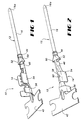
- Connector 10 is preferably of two piece construction comprising a contact member 12 and a crimp saddle attachment member 14, both of which are made of an electrically conductive material, such as brass.
- contact member 12 has a round or cylindrically shaped solid pin 16 along its forward portion.
- Pin 16 includes a rounded point 16a at its forward most end to facilitate insertion of the male pin connector 10 into a terminal cavity (not shown) and through sealing holes and membranes of an insert (not shown).
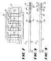
- the contact member 12 includes a flattened and dished portion 18 which is slightly arcuate in shape, as best shown in Figures 6, 8 and 9, for establishing good electrical contact between the contact member 12 and the conductive core of an electrical conductor cable (not shown) when the male pin connector 10 is attached to the core of an insulation end of the cable.
- Flattened portion 18 includes a plurality of transversely extending grooves 20 on its upper surface 18a and a plurality of transversely extending ribs 22 on its lower surface 18b.
- Pin 16 further includes at least one clamping portion 26 adjacent flattened portion 18 which includes at least one annular groove 24.
- a second clamping portion 28 may be formed with or without annular grooves 24.
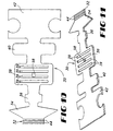
- the attachment member 14 is made from a sheet metal blank 30 stamped to the configuration shown in Figs. 10 and 11.
- the stamped blank 30 may have a generally rectangular first attachment portion 32 at its forward most end, a "winged" connect portion 34 adjacent first attachment portion 32, a second generally rectangular attachment portion 36, a generally rectangular core crimp portion 38, a generally rectangular insulation crimp portion 40, and a carrier strip portion 42 at its rearward most end.
- the first attachment portion 32 includes at least one transversely extending rib 44.
- the core crimp portion 38 includes a plurality of transversely extending grooves 39.
- the first 32 and second 36 attachment portions of attachment blank 30 are tightly rolled and formed into cylinders 46 and 48, respectively, around clamping portions 26 and 28 of pin 16, respectively.
- Such manipulation of portions 32 and 36 around pin 16 constitutes a first and second means of retaining contact member 12 in the attachment member 14, respectively.
- an important aspect of the first retaining means is that the ribs 44 on the first attachment portion 32 of attachment member 14 engage the corresponding annular grooves 24 in the first clamping portion 26 of pin 16 which enhances the connection or engagement between the two.
- the connect portion 34 of blank 30 is also rolled or manipulated about pin 16 to form a generally "triangular" or “arrow” shaped configuration having first 50 and second 52 wings which taper away and are spaced from the longitudinal axis of pin 16. Wings 50 and 52 are instrumental in attaching and securing connector 10 in an insulator connector housing (not shown).
- a primary retention feature of connector 10 in an insulator housing is accomplished by connect portion 34 of blank 30 after first and second wings 50, 52 have been formed.
- the core and insulation crimp portions 38, 40 of blank 30 are bent to form open generally U-shaped channels 54, 56, respectively.
- the flattened portion 18 of contact member 12 is positioned in the bottom of the channel 54 so that the plurality of transversely extending ribs 22 on the lower surface 18b of flattened portion 18 are received in and engage the corresponding plurality of transversely extending grooves 39 in channel 54.
- the core of an electrical cable is pressed against the grooved upper surface 18a of portion 18 and the channel 54 is crimped onto the core.
- the portion of the electrical cable still having insulation around the core is placed in the bottom of channel 56 whereupon channel 56 is crimped onto the insulation in a conventional manner.
- FIG. 1 Another important aspect of the present invention is the manner in which the flattened portion 18 is retained in channel 54 which constitutes a third means of retaining contact member 12 in the attachment member 14.
- a hole 58 is stamped in the bottom of saddle channel 54.
- a post 60 is extruded from the lower surface 18b of flattened portion 18.
- the post 60 and hole 58 are aligned with each other so that hole 58 receives post 60.
- the post 60 is peened or coined down forming a flange 62 which engages the saddle channel 54 at locations surrounding the hole 58 to securely retain the attachment member 14 to the contact member 12 and to stabilize the connection axially and in all directions.
- the post 60 By extruding the post 60 from the lower surface 18b of flattened portion 18 and peening the post inside the hole 58 previously stamped in the bottom of the wire crimp saddle channel 54, additional strength is gained in the saddle/channel area in the uncrimped and crimped state. This becomes evident if the contact member 12 and attachment member 14 are inadvertently bent or experience forces in the saddle/channel area. Moreover, by extruding and peening a post into a blanked hole, as opposed to a hole created on a seam, the likelihood of the post pulling out of location is greatly reduced. This also insures that the pin 16 remains in contact with the inside surface of the saddle/channel 54.
- the flattened portion 18 may be positioned in channel 54 and material punched from the upper surface 18a of flattened portion 18 into hole 58, the material that is punched forming post 60.
Landscapes
- Connections Effected By Soldering, Adhesion, Or Permanent Deformation (AREA)
- Coupling Device And Connection With Printed Circuit (AREA)
- Manufacturing Of Electrical Connectors (AREA)
- Multi-Conductor Connections (AREA)
- Connections By Means Of Piercing Elements, Nuts, Or Screws (AREA)
Claims (16)
- Ein elektrisch leitendes Kontaktglied (12) zur Verwendung in einem aus zwei Teilen bestehenden Stecker-Anschlußverbinder (10), wodurch elektrische Leiter in einem isolierten elektrischen Kabel mechanisch und elektrisch an einen Anschlußhohlraum angeschlossen werden, mit:(a) einem langgestreckten, zylinderförmig gestalteten massiven Stift (16) geformt entlang einem vorderen Abschnitt des Kontaktgliedes,(b) einer abgerundeten Spitze (16a) am Stift an seinem vorderen Ende zum Erleichtern des Einführens des Kontaktgliedes in den Anschlußhohlraum,(c) einem an einem hinteren Abschnitt des Kontaktgliedes geformten abgeflachten Abschnitt (18) mit einer leicht gewölbten Gestalt zum Ausbilden eines elektrischen Kontaktes zwischen dem Kontaktglied und den elektrischen Leitern in dem isolierten elektrischen Kabel,
dadurch gekennzeichnet, daß(d) der abgeflachte Abschnitt weiter eine Vielzahl von querverlaufenden Nuten (20) auf einer Oberseite und eine Vielzahl von querverlaufenden Rippen (22) auf einer Unterseite aufweist und(e) der Stift am abgeflachten Abschnitt weiter mindestens einen Klemmabschnitt (26) und dieser mindestens eine Ringnut (24) aufweist. - Das Kontaktglied nach Anspruch 1, wobei der Klemmabschnitt auf dem Stift zwei Ringnuten aufweist.
- Das Kontaktglied nach Anspruch 1 oder Anspruch 2, wobei der Stift am abgeflachten Abschnitt zwei Klemmabschnitte aufweist.
- Das Kontaktglied nach irgendeinem vorhergehenden Anspruch, wobei die Unterseite des abgeflachten Abschnittes weiter einen herausgepreßten Stiel aufweist.
- Ein elektrisch leitendes Crimpsattelbefestigungsglied (14) zur Verwendung in einem aus zwei Teilen bestehenden Stecker-Anschlußverbinder (10) mit einem Steckkontaktglied (12), wodurch ein isoliertes elektrisches Kabel mit einem Leiterkern mechanisch und elektrisch an einen Anschlußhohlraum angeschlossen wird, mit:und daß der Kerncrimpabschnitt zum Erfassen des Steckkontaktgliedes weiter eine Vielzahl von querverlaufenden Rippen (34) aufweist.(a) einem allgemein rechteckförmigen, an einem vorderen Ende des Befestigungsgliedes ausgebildeten ersten Befestigungsabschnitt (32), der zum Sichern des Steckkontaktgliedes an dem Befestigungsglied um das Steckkontaktglied dicht in eine allgemein zylinderförmige Gestalt gerollt und geformt ist,(b) einem mit Flügeln versehenen Verbindungsabschnitt (34) am ersten Befestigungsabschnitt, wobei der Verbindungsabschnitt (34) um das Steckkontaktglied herum zum Ausbilden einer allgemein dreieckförmig gestalteten Konfiguration mit einem ersten und einem zweiten Flügel manipulierbar ist, die sich von der Längsachse des Steckkontaktgliedes ausgehend verjüngen und zum Sichern des aus zwei Teilen bestehenden Stecker-Anschlußverbinders an dem Anschlußhohlraum wirksam werden,(c) einen zweiten allgemein rechteckförmigen Befestigungsabschnitt (36) an dem die Flügel aufweisenden Verbindungsabschnitt aufweist, wodurch der zweite Befestigungsabschnitt um das Steckkontaktglied herum zum weiteren Sichern des Steckkontaktgliedes an dem Befestigungsglied um das Steckkontaktglied dicht in eine allgemein zylinderförmige Gestalt gerollt und geformt ist,(d) einem allgemein rechteckförmigen Kerncrimpabschnitt (38) am zweiten allgemein rechteckförmigen Befestigungsabschnitt mit einer Gestaltung zum Ausbilden eines offenen, allgemein U-förmigen Kanals zum Aufnehmen des Steckkontaktgliedes und des Leiterkerns des elektrischen Kabels und(e) einem allgemein rechteckförmigen Isolationscrimpabschnitt (40) am Kerncrimpabschnitt mit einer Gestaltung zum Ausbilden eines offenen, allgemein U-förmigen Kanals zum Aufnehmen des isolierten elektrischen Kabels,
dadurch gekennzeichnet, daß der erste Befestigungsabschnitt zum Erfassen des Steckkontaktgliedes mindestens eine querverlaufende Rippe aufweist und daß das Befestigungsglied - Das Crimpsattelbefestigungsglied nach Anspruch 5, wobei das Befestigungsglied aus einem Blechrohling geformt ist.
- Ein aus zwei Teilen bestehender Stecker-Anschlußverbinder (10) zum mechanischen und elektrischen Anschließen eines isolierten elektrischen Kabels mit einem Leiterkern an einen Anschlußhohlraum mit:dadurch gekennzeichnet, daß der abgeflachte Abschnitt weiter auf einer Oberseite eine Vielzahl von querverlaufenden Nuten (20) und auf einer Unterseite eine Vielzahl von querverlaufenden Nuten (22) und der Stift weiter am abgeflachten Abschnitt einen ersten Klemmabschnitt (26) aufweist, der mindestens eine ringförmige Nut (24) aufweist, und daß der erste Befestigungsabschnitt mindestens eine mindestens eine Ringnut (24) in dem ersten Klemmabschnitt erfassende, querverlaufende Rippe (44) und daß der Kerncrimpabschnitt weiter eine Vielzahl von querverlaufenden Nuten (39) zum Erfassen der Vielzahl von querverlaufenden Rippen (22) auf der Unterseite des abgeflachten Abschnitts aufweist, wodurch der Kerncrimpabschnitt zum Pressen des Leiterkerns in die Vielzahl der querverlaufenden Nuten auf der Oberseite des abgeflachten Abschnitts auf den Leiterkern und den abgeflachten Abschnitt zum Ausbilden eines elektrischen Kontaktes zwischen dem Leiterkern und dem Kontaktglied gecrimpt werden soll.(a) einem elektrisch leitenden Kontaktglied (12) mit einem entlang einem vorderen Abschnitt des Kontaktgliedes ausgebildeten langgestreckten, zylinderförmig gestalteten Stift (16) und mit einem an einem hinteren Abschnitt des Kontaktgliedes ausgebildeten abgeflachten Abschnitt (18), der zum Ausbilden eines elektrischen Kontaktes zwischen dem Kontaktglied und dem Leiterkern in dem isolierten elektrischen Kabel eine leicht gewölbte Form aufweist,(b) einem aus einem Blechrohling geformten elektrisch leitenden Crimpsattelbefestigungsglied (14) mit einem ersten, an seinem vorderen Ende ausgebildeten, den Klemmabschnitt des Stiftes aufnehmenden und erfassenden Befestigungsabschnitt (32), der in dem Rohlingzustand allgemein rechteckförmig war, wobei der erste Befestigungsabschnitt zum Sichern des Kontaktgliedes am Befestigungsglied um den ersten Klemmabschnitt dicht in eine allgemein zylinderförmige Gestalt gerollt und geformt ist, und(c) wobei das Befestigungsglied weiter einen allgemein rechteckförmigen Kerncrimpabschnitt (38) aufweist, der zur Aufnahme des abgeflachten Abschnittes des Kontaktgliedes und des Leiterkerns des isolierten elektrischen Kabels unter Ausbildung eines offenen, allgemein U-förmigen Kanals gestaltet ist,
- Der aus zwei Teilen bestehende Stecker-Anschlußverbinder nach Anspruch 7, wobei die Unterseite des abgeflachten Abschnittes weiter einen herausgepreßten Stiel aufweist.
- Der aus zwei Teilen bestehende Stecker-Anschlußverbinder nach Anspruch 8, wobei der Kerncrimpabschnitt zum Aufnehmen des auf der Unterseite des abgeflachten Abschnittes herausgepreßten Stiels ein in dem Boden des U-förmigen Kanals ausgebildetes Loch aufweist.
- Der aus zwei Teilen bestehende Stecker-Anschlußverbinder nach Anspruch 9, wobei der herausgepreßte Stiel zum Ausbilden eines Flansches, der zum weiteren Verbessern des Sichems des Kontaktgliedes am Befestigungsglied den Kerncrimpabschnitt an das Loch umschließenden Stellen erfaßt, nach unten geprägt ist.
- Der aus zwei Teilen bestehende Stecker-Anschlußverbinder nach irgendeinem der Ansprüche 7 bis 10, wobei der Stift am abgeflachten Abschnitt weiter einen zweiten Klemmabschnitt aufweist.
- Der aus zwei Teilen bestehende Stecker-Anschlußverbinder nach Anspruch 11, wobei das Befestigungsglied zum Aufnehmen und Erfassen des zweiten Klemmabschnittes des Stiftes am ersten Befestigungsabschnitt weiter einen zweiten, allgemein rechteckförmigen Befestigungsabschnitt aufweist, der zum weiteren Sichern des Kontaktgliedes am Befestigungsglied um den zweiten Klemmabschnitt dicht in eine allgemein zylinderförmige Gestalt gerollt und geformt ist.
- Der aus zwei Teilen bestehende Stecker-Anschlußverbinder nach irgendeinem der Ansprüche 7 bis 12, wobei
das Befestigungsglied weiter am Kerncrimpabschnitt einen allgemein rechteckförmigen Isolationscrimpabschnitt aufweist, der unter Ausbildung eines offenen, allgemein U-förmigen Kanals zum Aufnehmen des isolierten elektrischen Kabels gestaltet ist, wobei der Isolationscrimpabschnitt zum weiteren Verbessern des Sicherns des elektrischen Kabels auf dem Befestigungsglied auf das isolierte elektrische Kabel gecrimpt ist. - Der aus zwei Teilen bestehende Stecker-Anschlußverbinder nach irgendeinem der Ansprüche 7 bis 13, wobei
das Befestigungsglied am ersten Befestigungsabschnitt weiter einen Flügel aufweisenden Verbindungsabschnitt aufweist, der zum Ausbilden einer allgemein dreieckförmig gestalteten Konfiguration mit einem ersten und einem zweiten Flügel, die sich von der Längsachse des Stiftes ausgehend verjüngen, auf den Stift aufgebogen ist, wobei die Flügel ein Sichern des Verbinders auf dem Anschlußhohlraum bewirken. - Der aus zwei Teilen bestehende Stecker-Anschlußverbinder nach irgendeinem der Ansprüche 7 bis 14, wobei der Stift an seinem vorderen Ende zum Erleichtern des Einführens des Kontaktgliedes in den Anschlußhohlraum eine abgerundete Spitze aufweist.
- Der aus zwei Teilen bestehende Stecker-Anschlußverbinder nach irgendeinem der Ansprüche 7 bis 15, wobei der erste Klemmabschnitt auf dem Stift zwei Ringnuten aufweist.
Applications Claiming Priority (2)
| Application Number | Priority Date | Filing Date | Title |
|---|---|---|---|
| US11081998P | 1998-12-01 | 1998-12-01 | |
| US110819P | 1998-12-01 |
Publications (2)
| Publication Number | Publication Date |
|---|---|
| EP1006613A1 EP1006613A1 (de) | 2000-06-07 |
| EP1006613B1 true EP1006613B1 (de) | 2003-08-06 |
Family
ID=22335122
Family Applications (1)
| Application Number | Title | Priority Date | Filing Date |
|---|---|---|---|
| EP99309630A Expired - Lifetime EP1006613B1 (de) | 1998-12-01 | 1999-12-01 | Verbesserter Messerkontaktsteckverbinder bestehend aus zwei Teilen |
Country Status (9)
| Country | Link |
|---|---|
| US (1) | US6290556B1 (de) |
| EP (1) | EP1006613B1 (de) |
| JP (1) | JP3401515B2 (de) |
| CN (1) | CN1127181C (de) |
| AT (1) | ATE246849T1 (de) |
| AU (1) | AU737947B2 (de) |
| BR (1) | BR9915784A (de) |
| CA (1) | CA2291806C (de) |
| DE (1) | DE69910154T2 (de) |
Families Citing this family (35)
| Publication number | Priority date | Publication date | Assignee | Title |
|---|---|---|---|---|
| US6712650B1 (en) * | 2003-03-26 | 2004-03-30 | Kingfont Precision Ind. Co., Ltd | Clamping structure for continuous terminal |
| JP4495066B2 (ja) * | 2005-10-27 | 2010-06-30 | 三菱電線工業株式会社 | ジョイントコネクタ |
| JP4846435B2 (ja) * | 2006-05-10 | 2011-12-28 | 矢崎総業株式会社 | 端子金具及び取付方法 |
| DE102006025610A1 (de) * | 2006-05-24 | 2007-11-29 | Apparatebau Kirchheim-Teck Gmbh | Kontakt für einen Stecker oder eine Steckdose |
| US7422494B2 (en) * | 2006-09-29 | 2008-09-09 | Tyco Electronics Corporation | Two-piece electrical terminal |
| US7976353B2 (en) * | 2006-09-29 | 2011-07-12 | Tyco Electronics Corporation | Two-piece electrical terminal |
| JP5078567B2 (ja) * | 2007-11-16 | 2012-11-21 | 矢崎総業株式会社 | アルミ電線用圧着端子 |
| US8303354B2 (en) * | 2008-02-15 | 2012-11-06 | Sumitomo Wiring Systems, Ltd. | Terminal connector and wire harness |
| JP2010055937A (ja) * | 2008-08-28 | 2010-03-11 | Sumitomo Wiring Syst Ltd | 端子金具及び端子金具付き電線 |
| JP5554975B2 (ja) | 2009-12-11 | 2014-07-23 | 矢崎総業株式会社 | 圧着端子 |
| JP4790851B2 (ja) * | 2010-03-11 | 2011-10-12 | 株式会社 ピー・エル | アルミニウム体の接続構造およびコネクタ |
| JP2011216253A (ja) * | 2010-03-31 | 2011-10-27 | Yazaki Corp | 圧着端子および圧着端子の電線に対する接続構造 |
| CN101895022A (zh) * | 2010-06-01 | 2010-11-24 | 鹤壁博昊机电有限公司 | 一种汽车电子线路防折断u型接头 |
| JP5773218B2 (ja) * | 2012-06-07 | 2015-09-02 | 住友電装株式会社 | 圧着端子 |
| DE102013201167A1 (de) * | 2013-01-24 | 2014-08-07 | Elringklinger Ag | Verfahren zum Herstellen einer elektrisch leitenden Verbindung zwischen einer elektrischen Leitung und einem elektrisch leitenden Bauteil und nach dem Verfahren hergestellte Baugruppe |
| US9395268B2 (en) | 2013-07-03 | 2016-07-19 | General Electric Company | Method and system to tolerance test a component |
| DE102013223570B4 (de) * | 2013-11-19 | 2021-06-24 | Te Connectivity Germany Gmbh | Stiftkontakt mit einem als Stanzbiegeteil gefertigten Kontaktkörper und einem massiven Kontaktstift |
| JP6439388B2 (ja) * | 2014-11-05 | 2018-12-19 | 株式会社オートネットワーク技術研究所 | 端子金具 |
| JP6532160B2 (ja) * | 2015-08-04 | 2019-06-19 | タイコエレクトロニクスジャパン合同会社 | 電気端子 |
| JP6563272B2 (ja) * | 2015-08-04 | 2019-08-21 | タイコエレクトロニクスジャパン合同会社 | 電気端子 |
| CN107019512B (zh) * | 2016-01-28 | 2022-05-24 | 皇家飞利浦有限公司 | 固定机构和mri系统 |
| JP6666211B2 (ja) * | 2016-07-19 | 2020-03-13 | タイコエレクトロニクスジャパン合同会社 | コンタクト |
| CN106252936B (zh) * | 2016-07-29 | 2018-07-10 | 安徽江淮汽车集团股份有限公司 | 一种汽车线束公端子 |
| KR101803530B1 (ko) * | 2016-09-19 | 2017-12-01 | 이경현 | 분리형 접속핀을 구비한 커넥터 |
| DE102016123162B4 (de) | 2016-11-30 | 2022-05-19 | Lear Corporation | Zweistückiger elektrischer anschlussstecker und verfahren zum zusammenfügen desselben |
| US10256561B2 (en) * | 2017-04-05 | 2019-04-09 | Te Connectivity Corporation | Terminal with ribbed contact spring |
| USD840942S1 (en) * | 2017-11-02 | 2019-02-19 | Vincent Paul DeVito | Terminal crimp socket |
| JP6652583B2 (ja) * | 2018-02-15 | 2020-02-26 | 株式会社オートネットワーク技術研究所 | 端子付き電線 |
| USD911962S1 (en) * | 2018-07-02 | 2021-03-02 | Japan Aviation Electronics Industry, Limited | Connector terminal |
| EP3832810B1 (de) * | 2019-12-02 | 2025-11-19 | Andreas Stihl AG & Co. KG | Motorangetriebenes garten- und/oder forstbearbeitungsgerät aufweisend einen steckverbinder zur elektrischen verbindung einer steckfahne mit einer elektrischen leitung eines motorangetriebenen garten- und/oder forstbearbeitungsgeräts |
| US11296441B2 (en) * | 2020-07-02 | 2022-04-05 | TE Connectivity Services Gmbh | Electrical terminal for flat flexible cables |
| US11476600B2 (en) * | 2020-12-18 | 2022-10-18 | Te Connectivity Solutions Gmbh | Electrical terminals with offset substrate mating portions |
| DE102021122892A1 (de) * | 2021-09-03 | 2023-03-09 | Te Connectivity Germany Gmbh | Mit einem Fenster zum Laserschweißen versehenes Halbfabrikat zur Herstellung eines elektrischen Kontaktelements sowie Verfahren zur Herstellung eines elektrischen Kontaktelements und elektrisches Kontaktelement |
| US11824319B2 (en) * | 2022-02-10 | 2023-11-21 | Aptiv Technologies AG | Electrical cable terminal with two piece coaxial crimped outer ferrule |
| DE102022124426A1 (de) * | 2022-09-22 | 2024-03-28 | Te Connectivity Germany Gmbh | Zweiteilige, elektrische Stift-Kontakteinrichtung |
Family Cites Families (22)
| Publication number | Priority date | Publication date | Assignee | Title |
|---|---|---|---|---|
| US1575656A (en) | 1923-11-22 | 1926-03-09 | Nathaniel W Stratford | Terminal for electrical conductors |
| US3517437A (en) | 1967-06-19 | 1970-06-30 | Beckman Instruments Inc | Method of forming a terminal structure in a refractory base |
| US3594702A (en) | 1969-07-31 | 1971-07-20 | Thomas & Betts Corp | Connector |
| US3654594A (en) * | 1970-10-09 | 1972-04-04 | Berg Electronics Inc | Crimp type terminal |
| US3812448A (en) | 1972-11-24 | 1974-05-21 | Thomas & Betts Corp | Electrical connector |
| US3892459A (en) | 1974-06-21 | 1975-07-01 | Amp Inc | Open barrel terminal and method for terminating an electrical wire therein |
| US3976385A (en) | 1974-10-09 | 1976-08-24 | Raychem Corporation | Method and apparatus for splicing lines |
| US4142771A (en) | 1974-10-16 | 1979-03-06 | Amp Incorporated | Crimp-type terminal |
| US4072394A (en) | 1976-03-01 | 1978-02-07 | The Bendix Corporation | Electrical contact assembly |
| US4120556A (en) | 1976-03-01 | 1978-10-17 | The Bendix Corporation | Electrical contact assembly |
| US4150355A (en) | 1978-01-04 | 1979-04-17 | Amp Incorporated | Electrical splices for wire wound resistors |
| US4253234A (en) * | 1978-12-26 | 1981-03-03 | The Bendix Corporation | Method of making electrical contact |
| US5387138A (en) * | 1991-07-09 | 1995-02-07 | Texas Instruments Incorporated | Printed circuit connector apparatus and method for making same |
| DE4200109A1 (de) * | 1992-01-04 | 1993-07-08 | Daut & Rietz Trw | Messerkontakt fuer elektrische steckverbinder |
| US5252088A (en) | 1992-10-05 | 1993-10-12 | General Motors Corporation | Sealed pass through electrical connector |
| US5399110A (en) * | 1994-02-04 | 1995-03-21 | General Motors Corporation | Two piece male pin terminal |
| GB9405303D0 (en) | 1994-03-17 | 1994-04-27 | Amp Gmbh | Electrical contact |
| DE9417197U1 (de) * | 1994-10-26 | 1995-03-02 | Siemens AG, 80333 München | Kontaktorgan für elektrische Steckverbindungen |
| JP3115805B2 (ja) | 1995-09-14 | 2000-12-11 | 矢崎総業株式会社 | 端子金具及び端子金具の製造方法 |
| DE19703984A1 (de) * | 1997-02-03 | 1998-08-06 | Grote & Hartmann | Hochstromkontaktelement |
| US6004172A (en) * | 1998-04-01 | 1999-12-21 | Tri-Star Electronics International, Inc. | Two piece pin/socket contact |
| US5993272A (en) * | 1998-05-20 | 1999-11-30 | Tescorp Seismic Products, Inc. | Electrical connector having detachable wire connection at cable entry end |
-
1999
- 1999-12-01 DE DE69910154T patent/DE69910154T2/de not_active Expired - Fee Related
- 1999-12-01 EP EP99309630A patent/EP1006613B1/de not_active Expired - Lifetime
- 1999-12-01 US US09/452,349 patent/US6290556B1/en not_active Expired - Fee Related
- 1999-12-01 BR BR9915784-5A patent/BR9915784A/pt not_active Application Discontinuation
- 1999-12-01 AU AU63018/99A patent/AU737947B2/en not_active Ceased
- 1999-12-01 CA CA002291806A patent/CA2291806C/en not_active Expired - Fee Related
- 1999-12-01 AT AT99309630T patent/ATE246849T1/de not_active IP Right Cessation
- 1999-12-01 JP JP34247999A patent/JP3401515B2/ja not_active Expired - Fee Related
- 1999-12-01 CN CN99127367A patent/CN1127181C/zh not_active Expired - Fee Related
Also Published As
| Publication number | Publication date |
|---|---|
| CN1260609A (zh) | 2000-07-19 |
| EP1006613A1 (de) | 2000-06-07 |
| CA2291806C (en) | 2003-05-27 |
| CA2291806A1 (en) | 2000-06-01 |
| CN1127181C (zh) | 2003-11-05 |
| DE69910154D1 (de) | 2003-09-11 |
| JP3401515B2 (ja) | 2003-04-28 |
| ATE246849T1 (de) | 2003-08-15 |
| AU737947B2 (en) | 2001-09-06 |
| DE69910154T2 (de) | 2004-06-09 |
| JP2000315561A (ja) | 2000-11-14 |
| US6290556B1 (en) | 2001-09-18 |
| AU6301899A (en) | 2000-08-17 |
| BR9915784A (pt) | 2001-09-18 |
Similar Documents
| Publication | Publication Date | Title |
|---|---|---|
| US6290556B1 (en) | Two piece male pin terminal connector | |
| EP0666616B1 (de) | Kontaktstift | |
| US6139363A (en) | Micro connector assembly and method of making the same | |
| US5147230A (en) | Two piece electrical female terminal | |
| US6254439B1 (en) | Female type terminal, assembling method of female type terminal, and connector for female type terminal | |
| US5224875A (en) | Terminal lug-water sealing plug coupling structure | |
| US4690481A (en) | Coaxial coupling | |
| US5975939A (en) | Twist termination connector | |
| CA1194569A (en) | Socket contact for electrical connector and method of manufacture | |
| US7226320B2 (en) | Connector having an improved locking structure | |
| US20250030213A1 (en) | High Deformation and Retention Ferrule | |
| EP1128472B1 (de) | Abgeschirmter Verbinder | |
| US5522739A (en) | Insulated terminal with integral dual flared barrel | |
| JP3392229B2 (ja) | 圧着端子組立体 | |
| US6955561B2 (en) | Inline connector | |
| EP1397846B1 (de) | Elektrischer nicht-quetschverbinder vom typ seite-an-seite | |
| US5433621A (en) | Waterproof plug and wire terminal with the waterproof plug | |
| EP0568927A1 (de) | Elektrischer Buchsenkontakt | |
| EP0722197B1 (de) | Schneidklemmenkontakt für Drähte mit verschiedenen Querschnitten | |
| US5554054A (en) | Temporary terminal retention feature | |
| CN219419586U (zh) | 连接端子及连接器 | |
| US20020048988A1 (en) | Press-connecting terminal | |
| JPH10340743A (ja) | 圧接端子及び圧接端子と電線との接続方法 | |
| MXPA99011118A (en) | Two-piece male sponge terminal connector | |
| JP2000082531A (ja) | 防水コネクタ |
Legal Events
| Date | Code | Title | Description |
|---|---|---|---|
| PUAI | Public reference made under article 153(3) epc to a published international application that has entered the european phase |
Free format text: ORIGINAL CODE: 0009012 |
|
| AK | Designated contracting states |
Kind code of ref document: A1 Designated state(s): AT BE CH CY DE DK ES FI FR GB GR IE IT LI LU MC NL PT SE |
|
| AX | Request for extension of the european patent |
Free format text: AL;LT;LV;MK;RO;SI |
|
| 17P | Request for examination filed |
Effective date: 20001129 |
|
| AKX | Designation fees paid |
Free format text: AT BE CH CY DE DK ES FI FR GB GR IE IT LI LU MC NL PT SE |
|
| GRAH | Despatch of communication of intention to grant a patent |
Free format text: ORIGINAL CODE: EPIDOS IGRA |
|
| GRAH | Despatch of communication of intention to grant a patent |
Free format text: ORIGINAL CODE: EPIDOS IGRA |
|
| GRAA | (expected) grant |
Free format text: ORIGINAL CODE: 0009210 |
|
| AK | Designated contracting states |
Designated state(s): AT BE CH CY DE DK ES FI FR GB GR IE IT LI LU MC NL PT SE |
|
| PG25 | Lapsed in a contracting state [announced via postgrant information from national office to epo] |
Ref country code: NL Free format text: LAPSE BECAUSE OF FAILURE TO SUBMIT A TRANSLATION OF THE DESCRIPTION OR TO PAY THE FEE WITHIN THE PRESCRIBED TIME-LIMIT Effective date: 20030806 Ref country code: LI Free format text: LAPSE BECAUSE OF FAILURE TO SUBMIT A TRANSLATION OF THE DESCRIPTION OR TO PAY THE FEE WITHIN THE PRESCRIBED TIME-LIMIT Effective date: 20030806 Ref country code: IT Free format text: LAPSE BECAUSE OF FAILURE TO SUBMIT A TRANSLATION OF THE DESCRIPTION OR TO PAY THE FEE WITHIN THE PRESCRIBED TIME-LIMIT;WARNING: LAPSES OF ITALIAN PATENTS WITH EFFECTIVE DATE BEFORE 2007 MAY HAVE OCCURRED AT ANY TIME BEFORE 2007. THE CORRECT EFFECTIVE DATE MAY BE DIFFERENT FROM THE ONE RECORDED. Effective date: 20030806 Ref country code: FI Free format text: LAPSE BECAUSE OF FAILURE TO SUBMIT A TRANSLATION OF THE DESCRIPTION OR TO PAY THE FEE WITHIN THE PRESCRIBED TIME-LIMIT Effective date: 20030806 Ref country code: CH Free format text: LAPSE BECAUSE OF FAILURE TO SUBMIT A TRANSLATION OF THE DESCRIPTION OR TO PAY THE FEE WITHIN THE PRESCRIBED TIME-LIMIT Effective date: 20030806 Ref country code: BE Free format text: LAPSE BECAUSE OF FAILURE TO SUBMIT A TRANSLATION OF THE DESCRIPTION OR TO PAY THE FEE WITHIN THE PRESCRIBED TIME-LIMIT Effective date: 20030806 Ref country code: AT Free format text: LAPSE BECAUSE OF FAILURE TO SUBMIT A TRANSLATION OF THE DESCRIPTION OR TO PAY THE FEE WITHIN THE PRESCRIBED TIME-LIMIT Effective date: 20030806 |
|
| REG | Reference to a national code |
Ref country code: GB Ref legal event code: FG4D |
|
| REG | Reference to a national code |
Ref country code: CH Ref legal event code: EP |
|
| REG | Reference to a national code |
Ref country code: IE Ref legal event code: FG4D |
|
| REF | Corresponds to: |
Ref document number: 69910154 Country of ref document: DE Date of ref document: 20030911 Kind code of ref document: P |
|
| PG25 | Lapsed in a contracting state [announced via postgrant information from national office to epo] |
Ref country code: SE Free format text: LAPSE BECAUSE OF FAILURE TO SUBMIT A TRANSLATION OF THE DESCRIPTION OR TO PAY THE FEE WITHIN THE PRESCRIBED TIME-LIMIT Effective date: 20031106 Ref country code: GR Free format text: LAPSE BECAUSE OF FAILURE TO SUBMIT A TRANSLATION OF THE DESCRIPTION OR TO PAY THE FEE WITHIN THE PRESCRIBED TIME-LIMIT Effective date: 20031106 Ref country code: DK Free format text: LAPSE BECAUSE OF FAILURE TO SUBMIT A TRANSLATION OF THE DESCRIPTION OR TO PAY THE FEE WITHIN THE PRESCRIBED TIME-LIMIT Effective date: 20031106 |
|
| PG25 | Lapsed in a contracting state [announced via postgrant information from national office to epo] |
Ref country code: ES Free format text: LAPSE BECAUSE OF FAILURE TO SUBMIT A TRANSLATION OF THE DESCRIPTION OR TO PAY THE FEE WITHIN THE PRESCRIBED TIME-LIMIT Effective date: 20031117 |
|
| NLV1 | Nl: lapsed or annulled due to failure to fulfill the requirements of art. 29p and 29m of the patents act | ||
| PG25 | Lapsed in a contracting state [announced via postgrant information from national office to epo] |
Ref country code: LU Free format text: LAPSE BECAUSE OF NON-PAYMENT OF DUE FEES Effective date: 20031201 Ref country code: IE Free format text: LAPSE BECAUSE OF NON-PAYMENT OF DUE FEES Effective date: 20031201 Ref country code: CY Free format text: LAPSE BECAUSE OF FAILURE TO SUBMIT A TRANSLATION OF THE DESCRIPTION OR TO PAY THE FEE WITHIN THE PRESCRIBED TIME-LIMIT Effective date: 20031201 |
|
| PG25 | Lapsed in a contracting state [announced via postgrant information from national office to epo] |
Ref country code: MC Free format text: LAPSE BECAUSE OF NON-PAYMENT OF DUE FEES Effective date: 20031231 |
|
| PG25 | Lapsed in a contracting state [announced via postgrant information from national office to epo] |
Ref country code: PT Free format text: LAPSE BECAUSE OF FAILURE TO SUBMIT A TRANSLATION OF THE DESCRIPTION OR TO PAY THE FEE WITHIN THE PRESCRIBED TIME-LIMIT Effective date: 20040106 |
|
| REG | Reference to a national code |
Ref country code: CH Ref legal event code: PL |
|
| ET | Fr: translation filed | ||
| PLBE | No opposition filed within time limit |
Free format text: ORIGINAL CODE: 0009261 |
|
| STAA | Information on the status of an ep patent application or granted ep patent |
Free format text: STATUS: NO OPPOSITION FILED WITHIN TIME LIMIT |
|
| 26N | No opposition filed |
Effective date: 20040507 |
|
| REG | Reference to a national code |
Ref country code: IE Ref legal event code: MM4A |
|
| PGFP | Annual fee paid to national office [announced via postgrant information from national office to epo] |
Ref country code: GB Payment date: 20071227 Year of fee payment: 9 |
|
| PGFP | Annual fee paid to national office [announced via postgrant information from national office to epo] |
Ref country code: DE Payment date: 20080131 Year of fee payment: 9 |
|
| PGFP | Annual fee paid to national office [announced via postgrant information from national office to epo] |
Ref country code: FR Payment date: 20071217 Year of fee payment: 9 |
|
| GBPC | Gb: european patent ceased through non-payment of renewal fee |
Effective date: 20081201 |
|
| REG | Reference to a national code |
Ref country code: FR Ref legal event code: ST Effective date: 20090831 |
|
| PG25 | Lapsed in a contracting state [announced via postgrant information from national office to epo] |
Ref country code: DE Free format text: LAPSE BECAUSE OF NON-PAYMENT OF DUE FEES Effective date: 20090701 |
|
| PG25 | Lapsed in a contracting state [announced via postgrant information from national office to epo] |
Ref country code: GB Free format text: LAPSE BECAUSE OF NON-PAYMENT OF DUE FEES Effective date: 20081201 |
|
| PG25 | Lapsed in a contracting state [announced via postgrant information from national office to epo] |
Ref country code: FR Free format text: LAPSE BECAUSE OF NON-PAYMENT OF DUE FEES Effective date: 20081231 |