EP1006630A2 - Chambre de combustion pour véhicule - Google Patents
Chambre de combustion pour véhicule Download PDFInfo
- Publication number
- EP1006630A2 EP1006630A2 EP99123630A EP99123630A EP1006630A2 EP 1006630 A2 EP1006630 A2 EP 1006630A2 EP 99123630 A EP99123630 A EP 99123630A EP 99123630 A EP99123630 A EP 99123630A EP 1006630 A2 EP1006630 A2 EP 1006630A2
- Authority
- EP
- European Patent Office
- Prior art keywords
- combustion chamber
- insulator body
- spark plug
- electrodes
- spark
- Prior art date
- Legal status (The legal status is an assumption and is not a legal conclusion. Google has not performed a legal analysis and makes no representation as to the accuracy of the status listed.)
- Granted
Links
Images

Classifications
-
- H—ELECTRICITY
- H01—ELECTRIC ELEMENTS
- H01T—SPARK GAPS; OVERVOLTAGE ARRESTERS USING SPARK GAPS; SPARKING PLUGS; CORONA DEVICES; GENERATING IONS TO BE INTRODUCED INTO NON-ENCLOSED GASES
- H01T13/00—Sparking plugs
- H01T13/02—Details
- H01T13/08—Mounting, fixing or sealing of sparking plugs, e.g. in combustion chamber
-
- F—MECHANICAL ENGINEERING; LIGHTING; HEATING; WEAPONS; BLASTING
- F02—COMBUSTION ENGINES; HOT-GAS OR COMBUSTION-PRODUCT ENGINE PLANTS
- F02B—INTERNAL-COMBUSTION PISTON ENGINES; COMBUSTION ENGINES IN GENERAL
- F02B75/00—Other engines
- F02B75/12—Other methods of operation
- F02B2075/125—Direct injection in the combustion chamber for spark ignition engines, i.e. not in pre-combustion chamber
-
- F—MECHANICAL ENGINEERING; LIGHTING; HEATING; WEAPONS; BLASTING
- F02—COMBUSTION ENGINES; HOT-GAS OR COMBUSTION-PRODUCT ENGINE PLANTS
- F02B—INTERNAL-COMBUSTION PISTON ENGINES; COMBUSTION ENGINES IN GENERAL
- F02B23/00—Other engines characterised by special shape or construction of combustion chambers to improve operation
- F02B23/08—Other engines characterised by special shape or construction of combustion chambers to improve operation with positive ignition
- F02B23/10—Other engines characterised by special shape or construction of combustion chambers to improve operation with positive ignition with separate admission of air and fuel into cylinder
- F02B23/101—Other engines characterised by special shape or construction of combustion chambers to improve operation with positive ignition with separate admission of air and fuel into cylinder the injector being placed on or close to the cylinder centre axis, e.g. with mixture formation using spray guided concepts
-
- Y—GENERAL TAGGING OF NEW TECHNOLOGICAL DEVELOPMENTS; GENERAL TAGGING OF CROSS-SECTIONAL TECHNOLOGIES SPANNING OVER SEVERAL SECTIONS OF THE IPC; TECHNICAL SUBJECTS COVERED BY FORMER USPC CROSS-REFERENCE ART COLLECTIONS [XRACs] AND DIGESTS
- Y02—TECHNOLOGIES OR APPLICATIONS FOR MITIGATION OR ADAPTATION AGAINST CLIMATE CHANGE
- Y02T—CLIMATE CHANGE MITIGATION TECHNOLOGIES RELATED TO TRANSPORTATION
- Y02T10/00—Road transport of goods or passengers
- Y02T10/10—Internal combustion engine [ICE] based vehicles
- Y02T10/12—Improving ICE efficiencies
Definitions
- the invention relates to a combustion chamber Internal combustion engine that has a fuel injector and one into a jet area of the injector protruding spark plug with two by one Insulator body includes separate electrodes.
- Such a combustion chamber is known from DE 196 27 524.
- a spark plug is used, the electrodes face each other on an air gap.
- the present invention solves the problem by instead of an air gap a series of against the electrodes and conductive insulated from each other Provides elements that a path for one Spark between the two electrodes on one side of the insulator body facing away from the injection valve establish.
- This feature Improvement in ignition behavior is attributed to that a long, particularly effective Spark arises, and that at the same time that of Injection valve facing away, i.e. in the slipstream lying side of the insulator body the speed the flow of the ignition mixture low and its turbulence is low so the spark is not is deflected.
- the smallest drops of the ignition mixture their movement closest to those in the combustion chamber Air flow follows, the one facing away from the injector Reach side of the insulator body. This Drops can be vaporized with the least amount of energy and therefore for the ignition of the mixture particularly valuable.
- the insulator body preferably has the shape of a tube, one of the electrodes passing through the tube extends and has a head which according to a preferred embodiment an end face of the pipe covered.
- the total width of this column can be Air gap width of a conventional spark plug correspond. But as soon as a spark on the If split columns are ignited, the individual unite Partial sparks quickly become one over the extending the entire distance between the electrodes Spark.
- This Shielding shield only causes small-scale additional Turbulence as that in its slipstream lying volume essentially from the insulator body is filled out.
- the shield can be on the wall of the combustion chamber or also be mounted on the spark plug, whereby the latter solution has the advantage of being application the invention also in a conventional Internal combustion engine only by exchanging the Allows spark plugs.
- FIG. 1 schematically shows an injection valve 10 and a spark plug 11 as related to each other are arranged in a combustion chamber, the wall 14 is only schematically indicated in sections.
- the Injector 10 injects the fuel onto its combustion chamber end 12 into the combustion chamber.
- the fuel spreads in about one Cone as indicated by dashed lines 13 is out in the combustion chamber and is doing so atomized so that a fuel-air mixture is formed.
- the thread 15 and the complementary internal thread the bore of the combustion chamber wall 14, which the Spark plug picks are sized so that the spark plug 11 then reaches a screwed position, when the ground electrode 16 and the conductive Elements 20 attach to the from the injector 10 facing away from the spark plug.
- an intermediate ring (not shown) be used between one Flange of the spark plug and a step of the bore the combustion chamber wall 14 or the outside thereof lie, and its thickness chosen in each case is that the spark plug is screwed tight Position reached when the conductive Elements 20 on the side facing away from the injection valve Side of the insulator body.
- This spark is extremely stable since it because of its close proximity to the surface of the insulator body 17 no significant turbulence Is exposed to currents that flow into it could tear away in one direction or another. It this creates a very stable spark that with the fuel-air mixture flowing out of the isolator body is well supplied and very reliable and ignites evenly.
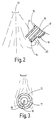
- FIG. 2 shows a modification of the arrangement from FIG 1.
- FIG. 3 shows a top view of this end in FIG axial direction.
- a shield 21 is in one piece with the thread 15 of the spark plug and the ground electrode 16 are formed and extends the entire length of the insulator body 17 up to the level of the head 19 the center electrode.
- This head is with this Designed as a hook-shaped element, that is from the longitudinal axis of the spark plug from the shield 21 in the radial direction to the edge of the cylindrical outer surface of the insulator body 17 extends.
- This design the head 19 excludes that an ignition spark between the head and the shield 21 skips. The spark is rather like that first embodiment, reliably along the conductive Elements 20 led to the ground electrode 16.
- the shield 21 also has the effect that most of the ejected from the injector Prevents fuel droplets directly to hit the insulator body 17 and to cool it too much, which leads to the formation of Cause cracks in its ceramic material and the lifespan could reduce the spark plug. So can the insulator body 17 in the operation of the internal combustion engine a constant high working temperature reach and prevents soot on the insulator body 17 sets off its insulation effect could affect.
- the Insulator body 17 against the body of the spark plug be freely rotatable and have a coding that in a complementary coding of the location hole the combustion chamber wall 14 engages so that during screwing the spark plug in the isolator from Start with the desired orientation in relation to the Injector is in and during screwing maintains.
- the shield can also rotatable and with the isolator body be firmly connected.
Landscapes
- Chemical & Material Sciences (AREA)
- Engineering & Computer Science (AREA)
- Combustion & Propulsion (AREA)
- Ignition Installations For Internal Combustion Engines (AREA)
- Spark Plugs (AREA)
- Combustion Methods Of Internal-Combustion Engines (AREA)
- Fuel-Injection Apparatus (AREA)
Applications Claiming Priority (2)
| Application Number | Priority Date | Filing Date | Title |
|---|---|---|---|
| DE19855791 | 1998-12-03 | ||
| DE19855791A DE19855791A1 (de) | 1998-12-03 | 1998-12-03 | Brennkammer für ein Kraftfahrzeug |
Publications (3)
| Publication Number | Publication Date |
|---|---|
| EP1006630A2 true EP1006630A2 (fr) | 2000-06-07 |
| EP1006630A3 EP1006630A3 (fr) | 2001-01-31 |
| EP1006630B1 EP1006630B1 (fr) | 2003-02-19 |
Family
ID=7889849
Family Applications (1)
| Application Number | Title | Priority Date | Filing Date |
|---|---|---|---|
| EP99123630A Expired - Lifetime EP1006630B1 (fr) | 1998-12-03 | 1999-11-27 | Chambre de combustion pour véhicule |
Country Status (3)
| Country | Link |
|---|---|
| EP (1) | EP1006630B1 (fr) |
| JP (1) | JP2000170635A (fr) |
| DE (2) | DE19855791A1 (fr) |
Cited By (1)
| Publication number | Priority date | Publication date | Assignee | Title |
|---|---|---|---|---|
| DE102006042457B4 (de) * | 2006-09-09 | 2010-06-10 | Ford Global Technologies, LLC, Dearborn | Ausgerichtete Zündkerze |
Families Citing this family (2)
| Publication number | Priority date | Publication date | Assignee | Title |
|---|---|---|---|---|
| DE102007024878A1 (de) | 2007-05-29 | 2008-12-04 | GM Global Technology Operations, Inc., Detroit | Zündkerze und Zylinderkopf dafür |
| DE102021214629A1 (de) | 2021-12-17 | 2023-06-22 | Robert Bosch Gesellschaft mit beschränkter Haftung | Zündkerze mit Element zur Strömungslenkung an brennraumseitiger Gehäusestirnseite |
Family Cites Families (6)
| Publication number | Priority date | Publication date | Assignee | Title |
|---|---|---|---|---|
| US2129576A (en) * | 1936-09-16 | 1938-09-06 | Frank A Gorny | Spark plug |
| US4272697A (en) * | 1979-03-01 | 1981-06-09 | Bernard Wax | Spark plug with annular rings in insulating core channels forming series gap |
| US5187404A (en) * | 1991-08-05 | 1993-02-16 | Cooper Industries, Inc. | Surface gap igniter |
| DE4331269C2 (de) * | 1993-09-15 | 1995-07-13 | Bosch Gmbh Robert | Verfahren zur Herstellung einer Zündkerze mit Gleitfunkenstrecke und nach den Verfahren hergestellte Zündkerzen |
| JPH0955282A (ja) * | 1995-06-08 | 1997-02-25 | Ngk Spark Plug Co Ltd | スパークプラグ |
| DE19627524A1 (de) * | 1996-07-09 | 1998-01-15 | Bosch Gmbh Robert | Zündkerze |
-
1998
- 1998-12-03 DE DE19855791A patent/DE19855791A1/de not_active Withdrawn
-
1999
- 1999-11-27 DE DE59904322T patent/DE59904322D1/de not_active Expired - Fee Related
- 1999-11-27 EP EP99123630A patent/EP1006630B1/fr not_active Expired - Lifetime
- 1999-12-03 JP JP11345366A patent/JP2000170635A/ja active Pending
Cited By (1)
| Publication number | Priority date | Publication date | Assignee | Title |
|---|---|---|---|---|
| DE102006042457B4 (de) * | 2006-09-09 | 2010-06-10 | Ford Global Technologies, LLC, Dearborn | Ausgerichtete Zündkerze |
Also Published As
| Publication number | Publication date |
|---|---|
| DE19855791A1 (de) | 2000-06-21 |
| EP1006630A3 (fr) | 2001-01-31 |
| JP2000170635A (ja) | 2000-06-20 |
| EP1006630B1 (fr) | 2003-02-19 |
| DE59904322D1 (de) | 2003-03-27 |
Similar Documents
| Publication | Publication Date | Title |
|---|---|---|
| EP0675272B1 (fr) | Dispositif d'allumage à préchambre | |
| EP1492953B1 (fr) | Combinaison soupape d'injection de carburant / bougie d'allumage | |
| EP1265329B1 (fr) | Bougie d'allumage d'un moteur à combustion interne | |
| DE102011053530B4 (de) | Vorkammerzündkerze Verfahren zum Herstellen einer Vorkammerzündkerze und Verfahren zum Fördern der Verbrennung in einer Brennkraftmaschine | |
| DE3731211C2 (fr) | ||
| DE102010045175B4 (de) | Zünder zum Zünden eines Brennstoff-Luft-Gemisches mittels einer HF-Korona-Entladung und Motor mit solchen Zündern | |
| DE10159910A1 (de) | Brennstoffeinspritzventil-Zündkerze-Kombination | |
| WO2007092972A1 (fr) | Bougie d'allumage | |
| DE112021003181T5 (de) | Zündkerze für eine Maschine mit interner Verbrennung | |
| DE102006000070A1 (de) | Zündkerze mit einem Schild für eine Erdungselektrode | |
| DE102012022872A1 (de) | Zündeinrichtung für einen Verbrennungsmotor und Verbrennungsmotor | |
| CH621852A5 (fr) | ||
| DE10340043B4 (de) | Zündkerze | |
| DE102007050634A1 (de) | Zündkerze | |
| EP1006630B1 (fr) | Chambre de combustion pour véhicule | |
| DE3017948C2 (fr) | ||
| WO1997036354A1 (fr) | Cosse de bougie d'allumage pour moteur a combustion interne | |
| DE60100653T2 (de) | Gleitentladungszündkerze mit radialem Funken | |
| DE69932684T2 (de) | Keramische Spitze für Glühsensor | |
| DE102015102745B4 (de) | Zündkerze für einen Vorkammer-Verbrennungsmotor | |
| EP0858139B1 (fr) | Bougie d'allumage | |
| DE102007055873A1 (de) | Plasmazündvorrichtung | |
| DE19627524A1 (de) | Zündkerze | |
| DE2444454A1 (de) | Zuendkerze, insbesondere fuer verbrennungsmotoren | |
| DE3404708A1 (de) | Einrichtung zum einspritzen von kraftstoff in brennraeume von brennkraftmaschinen |
Legal Events
| Date | Code | Title | Description |
|---|---|---|---|
| PUAI | Public reference made under article 153(3) epc to a published international application that has entered the european phase |
Free format text: ORIGINAL CODE: 0009012 |
|
| AK | Designated contracting states |
Kind code of ref document: A2 Designated state(s): DE FR GB IT |
|
| AX | Request for extension of the european patent |
Free format text: AL;LT;LV;MK;RO;SI |
|
| PUAL | Search report despatched |
Free format text: ORIGINAL CODE: 0009013 |
|
| AK | Designated contracting states |
Kind code of ref document: A3 Designated state(s): AT BE CH CY DE DK ES FI FR GB GR IE IT LI LU MC NL PT SE |
|
| AX | Request for extension of the european patent |
Free format text: AL;LT;LV;MK;RO;SI |
|
| RIC1 | Information provided on ipc code assigned before grant |
Free format text: 7H 01T 13/08 A, 7H 01T 13/52 B |
|
| 17P | Request for examination filed |
Effective date: 20010731 |
|
| AKX | Designation fees paid |
Free format text: DE FR GB IT |
|
| GRAG | Despatch of communication of intention to grant |
Free format text: ORIGINAL CODE: EPIDOS AGRA |
|
| 17Q | First examination report despatched |
Effective date: 20011207 |
|
| GRAG | Despatch of communication of intention to grant |
Free format text: ORIGINAL CODE: EPIDOS AGRA |
|
| GRAH | Despatch of communication of intention to grant a patent |
Free format text: ORIGINAL CODE: EPIDOS IGRA |
|
| GRAH | Despatch of communication of intention to grant a patent |
Free format text: ORIGINAL CODE: EPIDOS IGRA |
|
| GRAA | (expected) grant |
Free format text: ORIGINAL CODE: 0009210 |
|
| AK | Designated contracting states |
Designated state(s): DE FR GB IT |
|
| REG | Reference to a national code |
Ref country code: GB Ref legal event code: FG4D Free format text: NOT ENGLISH |
|
| REF | Corresponds to: |
Ref document number: 59904322 Country of ref document: DE Date of ref document: 20030327 Kind code of ref document: P |
|
| GBT | Gb: translation of ep patent filed (gb section 77(6)(a)/1977) | ||
| ET | Fr: translation filed | ||
| PGFP | Annual fee paid to national office [announced via postgrant information from national office to epo] |
Ref country code: GB Payment date: 20031103 Year of fee payment: 5 |
|
| PGFP | Annual fee paid to national office [announced via postgrant information from national office to epo] |
Ref country code: FR Payment date: 20031119 Year of fee payment: 5 |
|
| PGFP | Annual fee paid to national office [announced via postgrant information from national office to epo] |
Ref country code: DE Payment date: 20031215 Year of fee payment: 5 |
|
| PLBE | No opposition filed within time limit |
Free format text: ORIGINAL CODE: 0009261 |
|
| STAA | Information on the status of an ep patent application or granted ep patent |
Free format text: STATUS: NO OPPOSITION FILED WITHIN TIME LIMIT |
|
| 26N | No opposition filed |
Effective date: 20031120 |
|
| PG25 | Lapsed in a contracting state [announced via postgrant information from national office to epo] |
Ref country code: GB Free format text: LAPSE BECAUSE OF NON-PAYMENT OF DUE FEES Effective date: 20041127 |
|
| PG25 | Lapsed in a contracting state [announced via postgrant information from national office to epo] |
Ref country code: DE Free format text: LAPSE BECAUSE OF NON-PAYMENT OF DUE FEES Effective date: 20050601 |
|
| GBPC | Gb: european patent ceased through non-payment of renewal fee |
Effective date: 20041127 |
|
| PG25 | Lapsed in a contracting state [announced via postgrant information from national office to epo] |
Ref country code: FR Free format text: LAPSE BECAUSE OF NON-PAYMENT OF DUE FEES Effective date: 20050729 |
|
| REG | Reference to a national code |
Ref country code: FR Ref legal event code: ST |
|
| PG25 | Lapsed in a contracting state [announced via postgrant information from national office to epo] |
Ref country code: IT Free format text: LAPSE BECAUSE OF NON-PAYMENT OF DUE FEES Effective date: 20051127 |