EP1006643A2 - Generatorkühlung mit Kühlernachlaufmischung - Google Patents
Generatorkühlung mit Kühlernachlaufmischung Download PDFInfo
- Publication number
- EP1006643A2 EP1006643A2 EP99811016A EP99811016A EP1006643A2 EP 1006643 A2 EP1006643 A2 EP 1006643A2 EP 99811016 A EP99811016 A EP 99811016A EP 99811016 A EP99811016 A EP 99811016A EP 1006643 A2 EP1006643 A2 EP 1006643A2
- Authority
- EP
- European Patent Office
- Prior art keywords
- cooling
- generator
- cooling units
- units
- cooling medium
- Prior art date
- Legal status (The legal status is an assumption and is not a legal conclusion. Google has not performed a legal analysis and makes no representation as to the accuracy of the status listed.)
- Granted
Links
Images

Classifications
-
- H—ELECTRICITY
- H02—GENERATION; CONVERSION OR DISTRIBUTION OF ELECTRIC POWER
- H02K—DYNAMO-ELECTRIC MACHINES
- H02K9/00—Arrangements for cooling or ventilating
- H02K9/10—Arrangements for cooling or ventilating by gaseous cooling medium flowing in closed circuit, a part of which is external to the machine casing
- H02K9/12—Arrangements for cooling or ventilating by gaseous cooling medium flowing in closed circuit, a part of which is external to the machine casing wherein the cooling medium circulates freely within the casing
-
- H—ELECTRICITY
- H02—GENERATION; CONVERSION OR DISTRIBUTION OF ELECTRIC POWER
- H02K—DYNAMO-ELECTRIC MACHINES
- H02K9/00—Arrangements for cooling or ventilating
- H02K9/10—Arrangements for cooling or ventilating by gaseous cooling medium flowing in closed circuit, a part of which is external to the machine casing
Definitions
- the present invention relates to the field of power generators. It relates to a generator with a cooling system, which is generated by the heat generating Elements of the generator heated cooling medium from the generator sucks and the hot cooling medium to at least two working in parallel Cooling units conducts, and in which the cooling units cool the cooling medium before it in turn is directed to the generator's heat-generating elements becomes
- cooling medium usually air or another gas
- liquid media in a cooling circuit by the generator driven.
- the heat occurring on the hot components of the generator is transported away by the cooling medium and at another point in the cooling circuit withdrawn from the cooling medium via cooling units.
- the Example the cooling medium heated by the heat-generating elements of the generator from the generator of main fans attached to the rotor shaft sucked in.
- main fans are on the front and back of the Generator arranged, and a duct system directs that from the main fans blown cooling medium through cooling channels to a cooling arrangement, which mostly under the generator, in a foundation pit.
- the cooling medium is then when flowing through the substantially the entire length of the Generator extending and from several cooling units working in parallel composite cooling assembly extracted heat.
- the cold medium then appears in a channeled manner along the entire length back into the interior of the generator to the heat-generating elements, a closed cooling circuit educating.
- Cooling system is as insensitive to faults as possible. This is done, for example achieved that instead of a single large cooling unit several in parallel side by side working units are installed in the coolant flow. The Failure of a cooling unit can at least partially result from other units can be absorbed and destruction of the components by overheating can largely will avoid.
- Cooling units do not prevent the failure of one unit Damage to components. If a cooling unit fails, it will form hot gas streaks immediately behind the failed unit in the direction of flow, which quickly lead to critical material temperatures the components covered by it are exceeded. Particularly critical is the situation in the event of failure of edge coolers, since these are immediately strong and largely isolated hot gas streaks arise.
- a first preferred embodiment of the invention is characterized in that that the mixing is effected in a downstream of the cooling units arranged compensation space rigid guide plates are mounted, which the different Deflect coolant flows.
- Another embodiment is characterized in that the guide plates Mix cooling medium flows from neighboring cooling units with each other. This is particularly advantageous because it allows any modular Number of cooling units connected in parallel with the baffles can be provided and no bundling of the streams can be.
- Another embodiment is based on the fact that the baffles are in the compensation space in this way are arranged that the coolant flows provide a vortex are mixed together, which has the consequence that the mixing is essential runs more efficiently.
- baffles there are at least two baffles present, which of the adjacent sides of the neighboring Cooling units starting with sawtooth interlocking in alternating after the side of one and the other adjacent cooling unit inclined manner are drawn to a ceiling height above the outlet surface of the cooling units.
- This divides the equalization room into a distribution room and a mixing room, the distribution space in the cooling medium flow direction immediately behind the Cooling units is located, and the mixing chamber in the cooling medium flow direction immediately is arranged behind the distribution room.
- the flow from the distribution room to the As a result, the cooling medium flows become heat-generating elements of the generator neighboring cooling units in the mixing room due to the distraction to the Baffle plates mixed with swirls.
- Another advantage is that that the partial streams run against each other through this guide, which is the case with one Failure of an aggregate optimal heat exchange between uncooled hot and cooled cooling medium flow by countercurrent cooling.
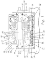
- Figure 1 shows a schematic longitudinal section through a operated in the suction cooling principle Generator.
- the generator is on the front and rear of the machine housing cover 13 bounded and longitudinally by an essentially cylindrical machine housing 14 includes.
- the housing comprises one of partial sheet metal bodies 20 formed stator sheet metal body, in which radial ventilation slots 26 between the different partial sheet metal bodies 20 are present.
- a rotor 22 is located in the center of the stator lamination body and the associated rotor shaft 12 is in bearing blocks 32 stored, which rest on brackets 25, which are on a foundation 24 stand.
- the foundation 24 has a foundation pit 10 which extends axially over the whole Length of the machine housing 24 extends and substantially the entire width of the machine housing 24 occupies.
- this foundation pit 10 is one Cooling arrangement consisting of several cooling units 23 attached. Stand there the inlet openings of the cooling units 23 with outflow spaces from both sides of the rotor 22 arranged main fans 11 in connection and the outlet openings of the cooling units 23 open into an equalization space 16.
- the Main fan 11 is fixed to the rotor shaft 12 and rotates with the same speed as the rotor 22.
- the flow path of cooling gas flowing through a generator is on the right Part of Figure 1 indicated by arrows.
- This cooling principle is about a so-called reverse or suction cooling, with hot gas 30.32 by means of fans 11 is supplied to the cooling units 23.
- In the direction of flow behind the Cooling units 23 distributes the cold cooling gas flow 31 behind the compensation space 16 onto the cold gas chambers 18, partial flows forming.
- a first one Partial stream flows between baffles 28 and an inner casing 17 directly to the rotor 22, a second flows through the winding head 21 into the machine air gap 29 between the rotor and stator, and a third stream of cooling gas passes through the cold gas chambers 18 and ventilation slots 26 in the machine air gap 29.
- the compensation space 16 like baffles 34 arranged above the various cooling units 23 in the compensation room 16 can be.
- the compensation space 16 is by the baffles 34 in distribution rooms 36 and divided into mixing rooms 35, and the baffles 34 form one in the side View substantially zigzag wall, but with the baffles 34 Do not separate distribution space 36 and mixing space 35 from each other, but vertically to the sectional plane of FIG. 1 interlock with each other like a saw tooth and allow the medium to flow through.
- FIG. 2 shows a perspective view of the arrangement of the guide plates 34 in the compensation space for two cooling units arranged side by side. You can see that inclined sawtooth-like intermeshing of the guide plates 34. Suppose one 40 of the cooling units 23 is no longer functional, while the neighboring one 41 still works, hot air flows out of the unit 40 and cold air out of the Unit 41. As a result of the guide plates 34, cold and hot coolant flow mix now opposed and subject to vortex when passing through the slots between the guide plates 34. In the situation shown in Figure 2 of two side by side arranged cooling units 23, it proves advantageous that Outflow behavior of the cooling medium on the sides is particularly influenced by the use of cover plates 37.
- Such cover plates 37 are at the ceiling height 44, on which the sides facing away from the cooling units 23 Baffles 34 meet, adjacent to the side walls 47 and parallel to the exit surfaces of the cooling units 23 retracted. This covers the cover plates 21 to the upper edges of the baffles 34 inclined towards them and ensure that all of the cooling medium flowing from the cooling unit 23 underneath the medium flowing from the neighboring aggregate is mixed and that If one of the units fails, there are no strands of hot cooling medium on the edges can form.
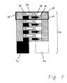
- FIG 3 shows the situation of Figure 2 in a supervision.
- the black cooling unit 40 is not functional while the other cooling unit 41 is working properly.
- the from the faulty aggregate 40 flowing hot air 42 is indicated by black arrows, the cooled one Air from the functional unit 41 is indicated by white arrows 43.
- the opposite mixing of streams 42 and 43 is clearly visible in the supervision.
- the opposite direction leads to an optimal mutual heat exchange and mixing of the two streams 42 and 43.
- the baffles 34 can corresponding to the width 46 of the units 23 are mutually strung together. Depending on the needs, e.g. consisting of two opposing baffles 34 Mixer cells 38 can be modularly strung together.
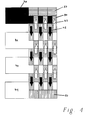
- FIG. 4 shows in a top view how the above cooling medium mixing concept also a plurality of cooling units 23 arranged side by side are used can be.
- the guide plates 34 become aggregates lying next to one another 23 simply overlapping one another. So it will Air that flows from an aggregate that is adjacent to two other aggregates is mixed with the air from both neighboring units. Again is it to avoid the particularly critical hot air strands on the edge necessary that cover plates 37 are drawn in at the edge coolers.
- baffles other than that described in the above embodiment are of course possible, and can the inventive concept in realize in a similar way. So it is conceivable, for example, the guide plates too additionally tilt to the side or not level, but in a more aerodynamic manner Structure shape.
Landscapes
- Engineering & Computer Science (AREA)
- Power Engineering (AREA)
- Motor Or Generator Cooling System (AREA)
- Cold Air Circulating Systems And Constructional Details In Refrigerators (AREA)
Abstract
Description
- die Bildung von Heissgassträhnen bei Ausfall von einzelnen Kühlern verhindern,
- keine grosse Veränderung der konventionell verwendeten Kühlsysteme notwendig macht,
- keine nennenswerten Druckverluste erzeugt.
- Fig. 1
- Schematische Darstellung eines Generators mit Saugkühlprinzip und Mischung des Kühlmediums im Ausgleichsraum;
- Fig. 2
- Perspektivische Ansicht eines Ausschnitts eines Ausgleichsraums mit Leitblechen;
- Fig. 3
- Aufsicht eines Ausgleichsraums mit seitlicher Aneinanderreihung von Leitblechen;
- Fig. 4
- Aufsicht mehrerer aneinandergereihter Kühlaggregate mit Leitblechen;
- 10
- Fundamentgrube
- 11
- Hauptventilator
- 12
- Rotorwelle
- 13
- Gehäusedeckel
- 14
- zylindrisches Maschinengehäuse
- 15
- Aussenverschalung
- 16
- Ausgleichsraum
- 17
- Innenverschalung
- 18
- Kaltgaskammer
- 19
- Heissgaskammer
- 20
- Teilblechkörper
- 21
- Wickelkopf
- 22
- Rotor
- 23
- Kühlanordnung
- 24
- Fundament
- 25
- Konsole
- 26
- Belüftungsschlitze
- 28
- Inneres Leitblech
- 29
- Maschinenluftspalt
- 30
- Heissluft vor 23
- 31
- Kaltluft nach 23
- 32
- Lagerbock
- 33
- Kühlkanal
- 34
- Leitblech
- 35
- Mischraum
- 36
- Verteilraum
- 37
- Deckblech
- 38
- Mischerzelle
- 40
- Ausgefallenes Kühlaggregat
- 41
- Funktionstüchtiges Kühlaggregat
- 42
- Heissluft aus 40
- 43
- Kaltluft aus 41
- 44
- Deckenhöhe
- 45
- Breite von 34
- 46
- Breite von 41
Claims (11)
- Generator mit einem Kühlsystem, welches von den wärmeerzeugenden Elementen des Generators erhitztes Kühlmedium aus dem Generator ansaugt und das heisse Kühlmedium zu wenigstens zwei parallel arbeitenden Kühlaggregaten (23) leitet, welche Kühlaggregate (23) das Kühlmedium abkühlen bevor es wiederum zu den wärmeerzeugenden Elementen des Generators geleitet wird,
dadurch gekennzeichnet, dass
Mittel (34,37) vorgesehen sind, welche die aus verschiedenen Kühlaggregaten (23) strömenden Kühlmediumströme (31) nach Austritt aus den Kühlaggregaten (23) und vor Zuleitung zu den wärmeerzeugenden Elementen des Generators miteinander vermischen. - Generator nach Anspruch 1, dadurch gekennzeichnet, dass das Kühlsystem nach dem Saugkühlprinzip arbeitet, bei welchem ein an einer Rotorwelle (12) angebrachter Hauptventilator (11) das von den wärmeerzeugenden Elementen des Generators erhitzte Kühlmedium ansaugt und anschliessend zu den Kühlaggregaten (23) treibt.
- Generator nach Anspruch 1, dadurch gekennzeichnet, dass die Kühlaggregate (23) in einer Fundamentgrube (10) angeordnet sind, welche den Generator teilweise aufnimmt.
- Generator nach Anspruch 3, dadurch gekennzeichnet, dass der Generator über eine Mehrzahl von parallel arbeitenden Kühlaggregaten (23) verfügt, welche sich im wesentlichen über die Breite der Fundamentgrube (10) erstrecken und welche an ihren Seiten wenigstens mittelbar aneinandergrenzen.
- Generator nach einem der Ansprüche 1 bis 4, dadurch gekennzeichnet, dass das Mischen der aus verschiedenen Kühlaggregaten (23) strömenden Kühlmediumströme (31) in einem in der Strömungsrichtung des Kühlmediums hinter den Kühlaggregaten (23) und vor den wärmeerzeugenden Elementen des Generators gelegenen Ausgleichsraum (16) stattfindet, und in diesem Ausgleichsraum (16) durch starre, Leitbleche (34) erfolgt, welche die verschiedenen Kühlmediumströme ablenken.
- Generator nach Anspruch 5, dadurch gekennzeichnet, dass das aus jeweils benachbarten Kühlaggregaten (23) strömende Kühlmedium vermischt wird.
- Generator nach Anspruch 6, dadurch gekennzeichnet, dass die Ablenkung der Kühlmediumströme benachbarter Kühlaggregate (23) durch Leitbleche (34) derart erfolgt, dass die Kühlmediumströme mit einem Wirbel versehen miteinander vermischt werden.
- Generator nach Anspruch 7, dadurch gekennzeichnet, dass im Ausgleichsraum (16) wenigstens zwei Leitbleche (34) angeordnet sind, dass die Leitbleche (34) von den aneinandergrenzenden Seiten der benachbarten Kühlaggregate (23) ausgehend sägezahnartig ineinandergreifend in abwechselnd nach der Seite des einen und des anderen benachbarten Kühlaggregates (23) geneigter Weise bis zu einer Dekkenhöhe (44) über der Austrittsfläche der Kühlaggregate (23) gezogen sind, so dass der Ausgleichsraum (16) in einen Verteilraum (36) und einen Mischraum (35) unterteilt wird, wobei der Verteilraum (36) in Kühlmediumströmungsrichtung unmittelbar hinter den Kühlaggregaten (23) liegt, und der Mischraum (35) in Kühlmediumströmungsrichtung unmittelbar hinter dem Verteilraum (36) angeordnet ist, und der Kühlmediumstrom benachbarter Kühlaggregate (23) beim Fluss vom Verteilraum (36) zu den wärmeerzeugenden Elementen des Generators im Mischraum (35) durch die Ablenkung an den Leitblechen (34) wirbelbehaftet vermischt wird.
- Generator nach Anspruch 8, dadurch gekennzeichnet, dass die Leitbleche (34) derart geneigt und ausgebildet sind, dass sie jeweils von der Seite des angrenzenden benachbarten Kühlaggregats (23) ausgehend die Deckenhöhe (44) im wesentlichen über der Mitte des nächsten Kühlaggregats (23) treffen.
- Generator nach Anspruch 9, dadurch gekennzeichnet, dass im Ausgleichsraum (16) über den in axialer Richtung des Generators aussenliegenden und damit randseitigen Kühlaggregaten (23) zusätzliche Deckbleche (37) eingezogen sind, welche parallel zur Austrittsfläche der Kühlaggregate (23) ausgerichtet auf der Deckenhöhe (44) liegen, sich über die ganze Breite der Kühlaggregate (23) erstrecken und welche so breit sind, dass sie an die von der Seite des benachbarten Kühlaggregats (23) ausgehenden Leitbleche angrenzen.
- Generator nach den Ansprüchen 3 und 9, dadurch gekennzeichnet, dass die Höhe zwischen der Austrittsfläche der Kühlaggregate (23) und der Oberkante der Fundamentgrube (10) in einem Bereich von 1-1.5m liegt, dass die Leitbleche (34) relativ zur Ebene der Austrittsfläche der Kühlaggregate (23) einen Winkel von 25°-30° einschliessen, und dass die quer zur Generatorhauptachse (12) gemessene Breite (45) aller Leitbleche (34) gleich ist und 1/10 bis 1/15 der gesamten Breite (46) der Kühlaggregate (23) ausmacht.
Applications Claiming Priority (2)
| Application Number | Priority Date | Filing Date | Title |
|---|---|---|---|
| DE19856455 | 1998-12-03 | ||
| DE19856455A DE19856455A1 (de) | 1998-12-03 | 1998-12-03 | Generatorkühlung mit Kühlernachlaufmischung |
Publications (3)
| Publication Number | Publication Date |
|---|---|
| EP1006643A2 true EP1006643A2 (de) | 2000-06-07 |
| EP1006643A3 EP1006643A3 (de) | 2003-01-29 |
| EP1006643B1 EP1006643B1 (de) | 2006-05-10 |
Family
ID=7890290
Family Applications (1)
| Application Number | Title | Priority Date | Filing Date |
|---|---|---|---|
| EP99811016A Expired - Lifetime EP1006643B1 (de) | 1998-12-03 | 1999-11-05 | Generatorkühlung mit Kühlernachlaufmischung |
Country Status (7)
| Country | Link |
|---|---|
| US (1) | US6239522B1 (de) |
| EP (1) | EP1006643B1 (de) |
| JP (1) | JP2000175408A (de) |
| KR (1) | KR20000047863A (de) |
| CN (1) | CN1132294C (de) |
| DE (2) | DE19856455A1 (de) |
| RU (1) | RU99125322A (de) |
Families Citing this family (7)
| Publication number | Priority date | Publication date | Assignee | Title |
|---|---|---|---|---|
| DE19925800C1 (de) * | 1999-06-03 | 2000-12-21 | Dresden Ev Inst Festkoerper | Wandler für akustische Oberflächenwellen |
| KR20050008921A (ko) * | 2003-07-14 | 2005-01-24 | 두산중공업 주식회사 | 발전기용 냉각기의 용량 결정 방법 |
| DE10335141B4 (de) * | 2003-07-31 | 2006-09-21 | Siemens Ag | Elektrische Maschine mit Kühlmittelführungskanal |
| US7777374B2 (en) * | 2004-09-09 | 2010-08-17 | Siemens Aktiengesellschaft | Electrical appliance |
| US8742635B2 (en) * | 2007-03-20 | 2014-06-03 | Alstom Technology Ltd. | Turbo generator with exciter having pressure recovery |
| JP4969669B2 (ja) * | 2010-04-01 | 2012-07-04 | 三菱電機株式会社 | 電気機器の液冷式冷却装置 |
| GB2546735A (en) * | 2016-01-25 | 2017-08-02 | Cummins Generator Tech Ltd | Air flow baffle for rotating electrical machine |
Family Cites Families (7)
| Publication number | Priority date | Publication date | Assignee | Title |
|---|---|---|---|---|
| US2427702A (en) * | 1944-05-27 | 1947-09-23 | Westinghouse Electric Corp | Turbogenerator cooling |
| DE868176C (de) * | 1950-08-10 | 1953-02-23 | Siemens Ag | Kuehleranordnung fuer gasgefuellte elektrische Maschinen |
| US2650994A (en) * | 1952-06-02 | 1953-09-01 | Gen Electric | Generator with removable top cooling dome |
| US2862121A (en) * | 1955-11-14 | 1958-11-25 | Allis Chalmers Mfg Co | Cooling gas system for dynamoelectric machines |
| US4071791A (en) * | 1976-06-01 | 1978-01-31 | General Electric Company | Reverse flow cooled dynamoelectric machines with novel cooling system |
| DE3724186A1 (de) * | 1987-07-17 | 1989-01-26 | Siemens Ag | Elektrische maschine mit geschlossenem kuehlkreislauf |
| DE19645272A1 (de) * | 1996-11-02 | 1998-05-07 | Asea Brown Boveri | Gasgekühlte elektrische Maschine |
-
1998
- 1998-12-03 DE DE19856455A patent/DE19856455A1/de not_active Withdrawn
-
1999
- 1999-11-05 EP EP99811016A patent/EP1006643B1/de not_active Expired - Lifetime
- 1999-11-05 DE DE59913408T patent/DE59913408D1/de not_active Expired - Lifetime
- 1999-11-30 US US09/450,725 patent/US6239522B1/en not_active Expired - Fee Related
- 1999-11-30 JP JP11340611A patent/JP2000175408A/ja active Pending
- 1999-12-02 RU RU99125322/09A patent/RU99125322A/ru not_active Application Discontinuation
- 1999-12-02 KR KR1019990054457A patent/KR20000047863A/ko not_active Withdrawn
- 1999-12-03 CN CN99122884A patent/CN1132294C/zh not_active Expired - Fee Related
Also Published As
| Publication number | Publication date |
|---|---|
| CN1255764A (zh) | 2000-06-07 |
| CN1132294C (zh) | 2003-12-24 |
| DE59913408D1 (de) | 2006-06-14 |
| KR20000047863A (ko) | 2000-07-25 |
| EP1006643B1 (de) | 2006-05-10 |
| EP1006643A3 (de) | 2003-01-29 |
| JP2000175408A (ja) | 2000-06-23 |
| DE19856455A1 (de) | 2000-06-08 |
| RU99125322A (ru) | 2001-11-10 |
| US6239522B1 (en) | 2001-05-29 |
Similar Documents
| Publication | Publication Date | Title |
|---|---|---|
| EP1787380B1 (de) | Set aus einer mehrzahl von kühlermodulen und einem maschinengehäuse | |
| EP0118802B1 (de) | Gasgekühlte Wechselstrommaschine | |
| EP3403319B1 (de) | Elektrische maschine | |
| DE102008022105B4 (de) | Flüssigkeitsgekühlte elektrische Maschine sowie Verfahren zur Kühlung einer solchen elektrischen Maschine | |
| DE3844337C2 (de) | ||
| EP0899856A2 (de) | Turbogenerator | |
| DE2608291A1 (de) | Gasgekuehlter generator-rotor mit erhoehter ventilation | |
| DE10018642C2 (de) | Drehelektromaschine | |
| DE2252733A1 (de) | Dynamomaschine | |
| WO2014072263A2 (de) | Elektrische maschine mit innerer luftkühlung | |
| DE102019213118A1 (de) | Stator für eine elektrische Maschine mit zwei Rotoren und elektrische Maschine mit zwei Rotoren und einem gemeinsamen Stator | |
| DE2612734A1 (de) | Raumklimaanlage mit ventilator und waermetauscher | |
| EP1006643B1 (de) | Generatorkühlung mit Kühlernachlaufmischung | |
| DE3044135C2 (de) | Luft-Luft-Wärmetauscher | |
| EP0739076B1 (de) | Elektrische Maschine | |
| EP0522210B1 (de) | Verfahren zum Kühlen einer umlaufenden elektrischen Maschine und elektrische Maschine zur Durchführung des Verfahrens | |
| EP0585644B1 (de) | Oberflächengekühlte, geschlossene elektrische Maschine | |
| DE102012221886A1 (de) | Kühlstruktur für eine elektrische Maschine | |
| DE19818149A1 (de) | Überströmkanäle eines Generators mit direkter Saugkühlung | |
| EP1705977B1 (de) | Gehäuse zur Aufnahme von elektronischen Steckbaugruppen | |
| DE1033322B (de) | Gaskuehlsystem fuer dynamoelektrische Maschinen | |
| DE10240419B3 (de) | Flächiges Kühlaggregat im Gegenstromprinzip | |
| EP2230746B1 (de) | Ständerkühlsystem für eine gehäuselose rotierende elektrische Maschine | |
| DE202005004448U1 (de) | Gehäuse zur Aufnahme von elektronischen Steckbaugruppen | |
| EP1122865B1 (de) | Rotationsmaschinenanordnung mit einer Rotationsmaschine und mit einer Kühlvorrichtung |
Legal Events
| Date | Code | Title | Description |
|---|---|---|---|
| PUAI | Public reference made under article 153(3) epc to a published international application that has entered the european phase |
Free format text: ORIGINAL CODE: 0009012 |
|
| AK | Designated contracting states |
Kind code of ref document: A2 Designated state(s): AT BE CH CY DE DK ES FI FR GB GR IE IT LI LU MC NL PT SE |
|
| AX | Request for extension of the european patent |
Free format text: AL;LT;LV;MK;RO;SI |
|
| RAP1 | Party data changed (applicant data changed or rights of an application transferred) |
Owner name: ALSTOM |
|
| RAP1 | Party data changed (applicant data changed or rights of an application transferred) |
Owner name: ALSTOM (SWITZERLAND) LTD |
|
| PUAL | Search report despatched |
Free format text: ORIGINAL CODE: 0009013 |
|
| AK | Designated contracting states |
Designated state(s): AT BE CH CY DE DK ES FI FR GB GR IE IT LI LU MC NL PT SE |
|
| AX | Request for extension of the european patent |
Extension state: AL LT LV MK RO SI |
|
| 17P | Request for examination filed |
Effective date: 20030705 |
|
| 17Q | First examination report despatched |
Effective date: 20030818 |
|
| AKX | Designation fees paid |
Designated state(s): DE FR GB IT |
|
| RAP1 | Party data changed (applicant data changed or rights of an application transferred) |
Owner name: ALSTOM TECHNOLOGY LTD |
|
| GRAP | Despatch of communication of intention to grant a patent |
Free format text: ORIGINAL CODE: EPIDOSNIGR1 |
|
| GRAS | Grant fee paid |
Free format text: ORIGINAL CODE: EPIDOSNIGR3 |
|
| GRAA | (expected) grant |
Free format text: ORIGINAL CODE: 0009210 |
|
| AK | Designated contracting states |
Kind code of ref document: B1 Designated state(s): DE FR GB IT |
|
| PG25 | Lapsed in a contracting state [announced via postgrant information from national office to epo] |
Ref country code: IT Free format text: LAPSE BECAUSE OF FAILURE TO SUBMIT A TRANSLATION OF THE DESCRIPTION OR TO PAY THE FEE WITHIN THE PRESCRIBED TIME-LIMIT;WARNING: LAPSES OF ITALIAN PATENTS WITH EFFECTIVE DATE BEFORE 2007 MAY HAVE OCCURRED AT ANY TIME BEFORE 2007. THE CORRECT EFFECTIVE DATE MAY BE DIFFERENT FROM THE ONE RECORDED. Effective date: 20060510 |
|
| REG | Reference to a national code |
Ref country code: GB Ref legal event code: FG4D Free format text: NOT ENGLISH |
|
| REF | Corresponds to: |
Ref document number: 59913408 Country of ref document: DE Date of ref document: 20060614 Kind code of ref document: P |
|
| GBT | Gb: translation of ep patent filed (gb section 77(6)(a)/1977) |
Effective date: 20060724 |
|
| ET | Fr: translation filed | ||
| PLBE | No opposition filed within time limit |
Free format text: ORIGINAL CODE: 0009261 |
|
| STAA | Information on the status of an ep patent application or granted ep patent |
Free format text: STATUS: NO OPPOSITION FILED WITHIN TIME LIMIT |
|
| 26N | No opposition filed |
Effective date: 20070213 |
|
| REG | Reference to a national code |
Ref country code: FR Ref legal event code: PLFP Year of fee payment: 17 |
|
| PGFP | Annual fee paid to national office [announced via postgrant information from national office to epo] |
Ref country code: IT Payment date: 20151125 Year of fee payment: 17 Ref country code: DE Payment date: 20151119 Year of fee payment: 17 Ref country code: GB Payment date: 20151118 Year of fee payment: 17 |
|
| PGFP | Annual fee paid to national office [announced via postgrant information from national office to epo] |
Ref country code: FR Payment date: 20151119 Year of fee payment: 17 |
|
| REG | Reference to a national code |
Ref country code: DE Ref legal event code: R082 Ref document number: 59913408 Country of ref document: DE Representative=s name: RUEGER, BARTHELT & ABEL, DE |
|
| REG | Reference to a national code |
Ref country code: DE Ref legal event code: R082 Ref document number: 59913408 Country of ref document: DE Representative=s name: RUEGER, BARTHELT & ABEL, DE Ref country code: DE Ref legal event code: R081 Ref document number: 59913408 Country of ref document: DE Owner name: GENERAL ELECTRIC TECHNOLOGY GMBH, CH Free format text: FORMER OWNER: ALSTOM TECHNOLOGY LTD., BADEN, CH |
|
| REG | Reference to a national code |
Ref country code: FR Ref legal event code: CD Owner name: ALSTOM TECHNOLOGY LTD, CH Effective date: 20161124 |
|
| REG | Reference to a national code |
Ref country code: DE Ref legal event code: R119 Ref document number: 59913408 Country of ref document: DE |
|
| GBPC | Gb: european patent ceased through non-payment of renewal fee |
Effective date: 20161105 |
|
| REG | Reference to a national code |
Ref country code: FR Ref legal event code: ST Effective date: 20170731 |
|
| PG25 | Lapsed in a contracting state [announced via postgrant information from national office to epo] |
Ref country code: FR Free format text: LAPSE BECAUSE OF NON-PAYMENT OF DUE FEES Effective date: 20161130 Ref country code: IT Free format text: LAPSE BECAUSE OF NON-PAYMENT OF DUE FEES Effective date: 20161105 |
|
| PG25 | Lapsed in a contracting state [announced via postgrant information from national office to epo] |
Ref country code: GB Free format text: LAPSE BECAUSE OF NON-PAYMENT OF DUE FEES Effective date: 20161105 Ref country code: DE Free format text: LAPSE BECAUSE OF NON-PAYMENT OF DUE FEES Effective date: 20170601 |