EP1006672A2 - Integrierter Echokompensator und programmierbarer Datenkompressionskodierer, -dekodierer - Google Patents
Integrierter Echokompensator und programmierbarer Datenkompressionskodierer, -dekodierer Download PDFInfo
- Publication number
- EP1006672A2 EP1006672A2 EP99122623A EP99122623A EP1006672A2 EP 1006672 A2 EP1006672 A2 EP 1006672A2 EP 99122623 A EP99122623 A EP 99122623A EP 99122623 A EP99122623 A EP 99122623A EP 1006672 A2 EP1006672 A2 EP 1006672A2
- Authority
- EP
- European Patent Office
- Prior art keywords
- telephone
- compression
- decoder
- echo canceller
- decoders
- Prior art date
- Legal status (The legal status is an assumption and is not a legal conclusion. Google has not performed a legal analysis and makes no representation as to the accuracy of the status listed.)
- Withdrawn
Links
Images


Classifications
-
- H—ELECTRICITY
- H04—ELECTRIC COMMUNICATION TECHNIQUE
- H04B—TRANSMISSION
- H04B3/00—Line transmission systems
- H04B3/02—Details
- H04B3/20—Reducing echo effects or singing; Opening or closing transmitting path; Conditioning for transmission in one direction or the other
- H04B3/23—Reducing echo effects or singing; Opening or closing transmitting path; Conditioning for transmission in one direction or the other using a replica of transmitted signal in the time domain, e.g. echo cancellers
-
- H—ELECTRICITY
- H04—ELECTRIC COMMUNICATION TECHNIQUE
- H04M—TELEPHONIC COMMUNICATION
- H04M1/00—Substation equipment, e.g. for use by subscribers
- H04M1/02—Constructional features of telephone sets
- H04M1/20—Arrangements for preventing acoustic feed-back
Definitions
- the present invention relates to telecommunication equipment in general, and in particular to echo cancellers and digital compression encoders/decoders.
- echo cancellers are placed in the telephone lines to sample an incoming telephone signal received from a user, calculate an echo estimate and subtract the echo estimate from a telephone signal being directed back to a user, in order to remove any echo.
- compression encoders/decoders only had the ability to perform a single type of conversion. That is, a set of telephone signals encoded with the A-law could be globally converted to the T-law or vice versa. Therefore, such converters had to be placed where all incoming and outgoing telephone signals were encoded according to the same companding law. If telephone signals were received from countries where the signals were encoded with different laws, additional encoders/decoders and extra routing of the signals had to be performed.
- the present invention is an echo converter that includes a number of programmable compression encoders/decoders that receive signals on a number of channels.
- a telephone signal on each channel can be encoded or decoded according to a programmed selection of a companding law.
- a controller dictates which law is used in each channel of the converter.
- the converters are programmed by the controller by supplying an address of an appropriate look-up table that is specific to the particular companding law selected in order to convert a digitally compressed telephone signal to a linear telephone signal and vice versa.
- the present invention is a combination echo canceller and compression encoder/decoder that can individually control the selection of a companding law used to convert each telephone signal applied to the encoder/decoder.
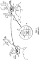
- FIGURE 1 illustrates an environmental view of a communication system, whereby a telephone signal that originates from a near end telephone 20 is transmitted to a far end telephone 22.
- the near end telephone is digitized and compressed or companded with a companding law prior to its transmission. If the telephone 20 is located in the United States, the compression is typically performed according to the T-law. If the far end telephone 22 is in Europe, the telephone signal is compressed according to the A-law.
- Disposed between the near end telephone 20 and the far end telephone 22 is an international exchange 24 that routes the call. Typically, the international exchange includes an echo canceller 26 that removes echoes created by the distance between the near end telephone 20 and the far end telephone 22.
- the echo canceller also includes a compression encoder/decoder that operates to translate a telephone signal between the T-law used at the near end and the A-law used at the far end.
- a compression encoder/decoder that operates to translate a telephone signal between the T-law used at the near end and the A-law used at the far end.
- FIGURE 2 A block diagram of a prior art echo canceller and compression encoder/decoder 40 is shown in FIGURE 2.
- the echo canceller and encoder/decoder 40 receives telephone signals from the near end telephone 22. Typically, these telephone signals are multiplexed onto a single telephone line and are de-multiplexed onto individual telephone lines by a de-multiplexer 42.
- the output of the de-multiplexer 42 feeds a compression encoder/decoder 44 that operates to convert the telephone signals from a compressed digital format to a linear format.
- the output of the encoder/decoder 44 is applied to inputs of an echo canceller 46.
- the telephone signals destined for a far end telephone are output from the echo canceller and applied to inputs of a compression encoder/decoder 48 which converts the signals from a linear format back to a compressed format.
- the outputs of the compression encoder/decoder 48 are fed to a multiplexer 50 that combines each of the signals onto a single telephone line directed to the far end.
- Telephone signals received from the far end are applied to a de-multiplexer 52 that separates each of the multiplexed telephone signals and applies them to individual telephone lines.
- Each of the telephone lines is applied to a compression encoder/decoder 54, where the signals are decompressed from a selected companding law to a linear format.
- Outputs of the echo canceller 46 that are directed to the near end are applied to an input of a compression encoder/decoder 58 where the signals are compressed according to a selected companding law and then applied to a multiplexer 60 that combines the signals onto a single telephone line for transmission to the near end.
- the prior art compression encoders/decoders 44, 48, 54, and 58 could only encode or decode all the telephone signals applied to the encoder/decoder according to the same companding law.
- the particular companding law selected was usually set by a logic signal applied to each of the encoders/decoders. Therefore, the combination echo canceller and compression encoder/decoder 40 shown in FIGURE 2 could not be used to receive telephone signals that are encoded according to different laws, or for transmitting telephone signals to countries that utilize different companding laws.
- FIGURE 3 illustrates a combination echo canceller and compression encoder/decoder that is constructed according to the present invention.
- the echo canceller and compression encoder/decoder 100 receives telephone signals on a single telephone line from a near end source and applies them to a de-multiplexer 102 that separates out each individual telephone signal and applies it to individual telephone lines.
- Each of the telephone lines from the de-multiplexer 102 feeds a separate channel of a programmable compression encoder/decoder 104.
- Each channel of the compression encoder/decoder 104 is individually programmable to select the companding law to be used with the telephone signal applied to that particular channel.
- the compression encoder/decoder 104 operates to convert the telephone signals from a digital compressed format to a digital linear format for application to an echo converter 106.
- An output of the echo converter 106 is applied to a programmable compression encoder/decoder 108 having a number of channels. Again, each channel is individually programmed to select a companding law used to encode the telephone signals in that particular channel.
- the output of the compression encoder/decoder 108 is applied to a multiplexer 110 that combines all the telephone signals onto a single telephone line for transmission to the far end destinations.
- Telephone signals received on a single telephone line from the far end destinations are applied to a de-multiplexer 112 that separates out each telephone signal and applies them to individual telephone lines which are again applied to a programmable compression encoder/decoder 114.
- Each channel of the compression encoder/decoder 114 converts the telephone signal from a digitally compressed format to a linear format and applies the linear telephone signals to the echo canceller 106.
- the outputs of the echo canceller 106 are applied to a number of channels of a programmable compression encoder/decoder 116 that convert the telephone signals from a linear format to a selected compressed format using a companding law that is selected for each particular channel.
- the output of the compression encoder/decoder 116 is fed to a multiplexer 118 that combines the signals onto a single telephone line for transmission to the near end subscriber.
- each channel of the compression encoders/decoders 104, 110, 112, and 116 is independently programmable to select the companding law that is used to encode/decode a telephone signal.
- Controlling the encoders/decoders is a controller 120 that receives software commands from a processing circuit (not shown) that set up the parameters for each telephone call.
- logic signals received from circuits that supply the actual telephone signals are applied on a set of pins 122 in order to allow the hardware units to select the particular companding law used to encode or decode a telephone signal.
- each channel of the converters includes a register 130 that contains a pointer to a look-up table in a memory that specifies the conversion between a particular sample of the telephone signal that is encoded according to the selected companding law and a corresponding sample encoded in a linear format.
- the selection of the particular companding law used for the telephone signals in a channel is made by selecting the correct look-up table for that desired companding law.
- each channel of the compression encoders/decoders is individually programmable, it is possible to receive telephone signals from either the near end or far end that are encoded according to different companding laws with the same echo canceler and compression encoder/decoder.
- a series of registers 132 and 134 in the controller 120 allow the controller 120 to control the particular companding law used for each channel of the compression encoders/decoders 104, 110, 112, and 116. It will be appreciated that those channels on the same side of the echo canceller, i.e., that receive telephone signals from and direct signals to the same user at the near end or far end, are programmed to utilize the same companding law for decoding and encoding the telephone signals.
- FIGURES 4A and 4B are flow charts illustrating the method by which the programmable echo canceller and compression encoder/decoder of the present invention operates.
- the controller 120 receives software commands from a processor in charge of setting up a call and logic signals from individual hardware units that supply the telephone signals to the compression encoders/decoders in order to select the type of conversion necessary for each channel.
- the software commands or hardware units may require individual channels to be encoded or decoded with a particular companding law. Alternatively, the software commands or hardware units may require that all channels of the compression encoders/decoders utilize the same companding law.
- the controller 120 determines whether a software command has been received that requests that an individual channel be converted according to a selected companding law. If the answer to step 200 is no, processing proceeds according to the steps shown in FIGURE 4B described below.
- the controller 120 determines at a step 202 whether conversion is disabled for specific channels by channel individual register settings. Step 202 operates as a check to confirm whether the converters are disabled by software sources. If the answer to step 202 is yes, an individual channel is to be compressed with a selected companding law identical for near end and far. If the answer to step 202 is no, the controller 120 determines at a step 204 whether the input signals from hardware units to the echo canceller and compression encoders/decoders are enabled. If the answer to step 204 is yes, then the controller 120 determines at a step 206 whether at least one hardware unit requests an individual channel to be disabled.
- step 206 If the answer to step 206 is no, then the channel pairs on the near end and far end of the echo canceller and compression encoder/decoder operate to perform a channel individual conversion as specified by an appropriate register in the controller 120. If the answer to step 206 is yes, then processing proceeds to a step 210, wherein channel individual near end and far end pairs are set to utilize an identical companding law.
- step 204 If the answer to step 204 is no, and the hardware units are not enabled, then the channel pairs are programmed to perform a channel individual conversion as specified by the registers in the controller 120 at a step 208 as described above.
- step 220 the controller 120 determines whether a global conversion was disabled for specific channels by a software command. If the answer to step 220 is yes, then all disabled near end and far end channel pairs are programmed to use the same companding law and no conversion is performed in these channels. If the answer to step 220 is no, then processing proceeds to a step 224, wherein the controller 120 determines if the hardware units that control the selection of a particular companding law to be utilized in the channels are enabled. If the answer to step 224 is no, then processing proceeds to a step 226 and all near end and far end channel pairs perform a global conversion as specified by the registers in the controller.
- step 224 determines if at least one hardware unit has requested disabling of specific channels. If the answer to step 228 is no, then processing proceeds to step 226 and the near end and far end channel pairs are programmed to perform a global conversion as specified by a register in the controller. If the answer to step 228 is yes, then processing returns to step 232 and all disabled channel pairs are programmed to utilize the same companding law at the near end and far end.
- the present invention allows a single echo canceller and compression encoder/decoder to be used in environments where telephone calls are transmitted to and received from locations that use different companding laws on the near end and far end.
- the present invention provides more flexibility and reduces the need for additional hardware in telecommunication switching equipment.
- the present invention is not limited for use in international exchange equipment but can be used in such devices as switching stations that transfer telephone calls between different formats, i.e., cellular to fixed network, at an interworking unit (IWU) that connects a public switched telephone network (PSTN) to an asynchronous transfer mode (ATM) network, or voice over IP gateway that connects a PSTN with an internet protocol (IP) network.
- IWU interworking unit
- PSTN public switched telephone network
- ATM asynchronous transfer mode
- IP gateway internet protocol
Landscapes
- Engineering & Computer Science (AREA)
- Signal Processing (AREA)
- Computer Networks & Wireless Communication (AREA)
- Telephonic Communication Services (AREA)
- Cable Transmission Systems, Equalization Of Radio And Reduction Of Echo (AREA)
- Transmission Systems Not Characterized By The Medium Used For Transmission (AREA)
- Compression, Expansion, Code Conversion, And Decoders (AREA)
- Telephone Function (AREA)
Applications Claiming Priority (4)
| Application Number | Priority Date | Filing Date | Title |
|---|---|---|---|
| US11025598P | 1998-11-30 | 1998-11-30 | |
| US110255P | 1998-11-30 | ||
| US38980299A | 1999-09-03 | 1999-09-03 | |
| US389802 | 1999-09-03 |
Publications (2)
| Publication Number | Publication Date |
|---|---|
| EP1006672A2 true EP1006672A2 (de) | 2000-06-07 |
| EP1006672A3 EP1006672A3 (de) | 2005-02-02 |
Family
ID=26807847
Family Applications (1)
| Application Number | Title | Priority Date | Filing Date |
|---|---|---|---|
| EP99122623A Withdrawn EP1006672A3 (de) | 1998-11-30 | 1999-11-13 | Integrierter Echokompensator und programmierbarer Datenkompressionskodierer, -dekodierer |
Country Status (4)
| Country | Link |
|---|---|
| EP (1) | EP1006672A3 (de) |
| JP (1) | JP2000216712A (de) |
| KR (1) | KR20000047785A (de) |
| TW (1) | TW441200B (de) |
Cited By (2)
| Publication number | Priority date | Publication date | Assignee | Title |
|---|---|---|---|---|
| US7065057B2 (en) | 2000-09-21 | 2006-06-20 | Siemens Aktiengesellschaft | Method and apparatus for improving the transmission quality in a packet-oriented data transmission network |
| US8694326B2 (en) | 2010-02-24 | 2014-04-08 | Panasonic Corporation | Communication terminal and communication method |
Family Cites Families (13)
| Publication number | Priority date | Publication date | Assignee | Title |
|---|---|---|---|---|
| JPH03270424A (ja) * | 1990-03-20 | 1991-12-02 | Fujitsu Ltd | 音声データ圧縮多段接続方式 |
| JP2924137B2 (ja) * | 1990-09-07 | 1999-07-26 | 日本電気株式会社 | エコーキャンセラ制御方式 |
| US5243342A (en) * | 1990-09-28 | 1993-09-07 | Stratacom, Inc. | Integrated PCM level control and conversion using a lookup table |
| JP2594202B2 (ja) * | 1992-02-25 | 1997-03-26 | 三洋電機株式会社 | デジタル信号処理装置 |
| JPH07193619A (ja) * | 1993-10-27 | 1995-07-28 | Canon Inc | デジタル電話機及びその動作方法 |
| JPH07226961A (ja) * | 1994-02-14 | 1995-08-22 | Nippon Telegr & Teleph Corp <Ntt> | 拡声通信システム及び反響消去装置を有する交換機 |
| JP3588679B2 (ja) * | 1994-03-17 | 2004-11-17 | 富士通株式会社 | 情報提供装置 |
| US5790632A (en) * | 1994-09-30 | 1998-08-04 | Qualcom Incorporated | Method and apparatus for echo canceling accounting for companding induced quantization error |
| US5623491A (en) * | 1995-03-21 | 1997-04-22 | Dsc Communications Corporation | Device for adapting narrowband voice traffic of a local access network to allow transmission over a broadband asynchronous transfer mode network |
| JPH08274889A (ja) * | 1995-03-29 | 1996-10-18 | Fujitsu Ltd | 伝送装置 |
| JPH0955964A (ja) * | 1995-08-10 | 1997-02-25 | Fujitsu Ltd | 交換システム |
| KR100892950B1 (ko) * | 1996-02-09 | 2009-04-09 | 아이-링크 시스템즈, 아이엔씨. | 음성 인터넷 전송 시스템 |
| JP3462703B2 (ja) * | 1997-04-17 | 2003-11-05 | 株式会社日立コミュニケーションテクノロジー | 音声圧縮ディジタルリンクの接続制御方式 |
-
1999
- 1999-11-13 EP EP99122623A patent/EP1006672A3/de not_active Withdrawn
- 1999-11-24 TW TW088120520A patent/TW441200B/zh not_active IP Right Cessation
- 1999-11-30 KR KR1019990053746A patent/KR20000047785A/ko not_active Withdrawn
- 1999-11-30 JP JP11340842A patent/JP2000216712A/ja active Pending
Cited By (3)
| Publication number | Priority date | Publication date | Assignee | Title |
|---|---|---|---|---|
| US7065057B2 (en) | 2000-09-21 | 2006-06-20 | Siemens Aktiengesellschaft | Method and apparatus for improving the transmission quality in a packet-oriented data transmission network |
| DE10046901A9 (de) * | 2000-09-21 | 2006-08-03 | Siemens Ag | Verfahren und Vorrichtung zur Verbesserung der Übertragungsqualität in einem paket-orientierten Datenübertragungsnetz |
| US8694326B2 (en) | 2010-02-24 | 2014-04-08 | Panasonic Corporation | Communication terminal and communication method |
Also Published As
| Publication number | Publication date |
|---|---|
| TW441200B (en) | 2001-06-16 |
| JP2000216712A (ja) | 2000-08-04 |
| EP1006672A3 (de) | 2005-02-02 |
| KR20000047785A (ko) | 2000-07-25 |
Similar Documents
| Publication | Publication Date | Title |
|---|---|---|
| EP0637179B1 (de) | TDMA auf einem PCM-Übertragungsweg eines zellulären Kommunikationssystems | |
| US5638363A (en) | Switched telecommunications network with bandwidth management for different types of multiplexed traffic | |
| US5526350A (en) | Communication network with bandwidth managers for allocating bandwidth to different types of traffic | |
| US6295302B1 (en) | Alternating speech and data transmission in digital communications systems | |
| US20050008030A1 (en) | Procedure for exchanging useful information generated according to different coding laws between at least 2 pieces of user terminal equipment | |
| SE517903C2 (sv) | Nät för telekommunikation via radio och förfarande för diskret samtalshänvisning via kodkonverterarförbikoppling | |
| KR19990035852A (ko) | 통신네트워크를 통한 디지털 신호의 전송 방법 및 장치 | |
| WO1992003023A1 (fr) | Materiel de telecommunications avec fonction de commutation a repetition | |
| US6324515B1 (en) | Method and apparatus for asymmetric communication of compressed speech | |
| US6385314B1 (en) | Transmission device control system equipped with high-efficiency coding scheme in communication network | |
| US6169750B1 (en) | Voice packet multiplexer with voice transit switching function | |
| EP1006672A2 (de) | Integrierter Echokompensator und programmierbarer Datenkompressionskodierer, -dekodierer | |
| US5499240A (en) | Switched communication network with bandwidth managers for achieving end-to-end data compression during transport | |
| US6285747B1 (en) | Telecommunications apparatus and method | |
| JP2775846B2 (ja) | 時分割多重化装置 | |
| EP0705052A2 (de) | Kommunikationssystem für digitale Sprechsignale | |
| US6178182B1 (en) | Method and communication system for the transmission of compressed voice information in a communication network | |
| KR100438234B1 (ko) | 인터넷 망에서의 음성 및 팩시밀리 가입자 장치 | |
| JPS63172555A (ja) | 音声符号化構内交換方式 | |
| JP2818542B2 (ja) | 高能率音声符号化復号化ディジタル1リンク中継交換方式 | |
| KR100263548B1 (ko) | 종합정보통신망(isdn)용 복합 접속 교환장치 | |
| JP3056269U (ja) | サービス総合ディジタル通信網を用いたファクシミリ通信装置 | |
| AU756634B2 (en) | Alternating speech and data transmission in digital communications systems | |
| US6810117B1 (en) | Method and circuit for simultaneously establishing communication links between a subscriber station and further subscriber stations | |
| US7324557B2 (en) | Method, switching devices and remote connection unit for transmitting data having a reduced bandwidth |
Legal Events
| Date | Code | Title | Description |
|---|---|---|---|
| PUAI | Public reference made under article 153(3) epc to a published international application that has entered the european phase |
Free format text: ORIGINAL CODE: 0009012 |
|
| AK | Designated contracting states |
Kind code of ref document: A2 Designated state(s): AT BE CH CY DE DK ES FI FR GB GR IE IT LI LU MC NL PT SE |
|
| AX | Request for extension of the european patent |
Free format text: AL;LT;LV;MK;RO;SI |
|
| PUAL | Search report despatched |
Free format text: ORIGINAL CODE: 0009013 |
|
| AK | Designated contracting states |
Kind code of ref document: A3 Designated state(s): AT BE CH CY DE DK ES FI FR GB GR IE IT LI LU MC NL PT SE |
|
| AX | Request for extension of the european patent |
Extension state: AL LT LV MK RO SI |
|
| 17P | Request for examination filed |
Effective date: 20050318 |
|
| 17Q | First examination report despatched |
Effective date: 20050418 |
|
| AKX | Designation fees paid |
Designated state(s): DE FR GB IT |
|
| GRAP | Despatch of communication of intention to grant a patent |
Free format text: ORIGINAL CODE: EPIDOSNIGR1 |
|
| STAA | Information on the status of an ep patent application or granted ep patent |
Free format text: STATUS: THE APPLICATION IS DEEMED TO BE WITHDRAWN |
|
| 18D | Application deemed to be withdrawn |
Effective date: 20071002 |