EP1006686B1 - Verfahren und Vorrichtung zur Steuerung einer Frequenz durch ein asynchrones Übertragungsnetzwerk und Funktelefonienetzwerk, das die Vorrichtung verwendet - Google Patents
Verfahren und Vorrichtung zur Steuerung einer Frequenz durch ein asynchrones Übertragungsnetzwerk und Funktelefonienetzwerk, das die Vorrichtung verwendet Download PDFInfo
- Publication number
- EP1006686B1 EP1006686B1 EP99402641A EP99402641A EP1006686B1 EP 1006686 B1 EP1006686 B1 EP 1006686B1 EP 99402641 A EP99402641 A EP 99402641A EP 99402641 A EP99402641 A EP 99402641A EP 1006686 B1 EP1006686 B1 EP 1006686B1
- Authority
- EP
- European Patent Office
- Prior art keywords
- offset
- range
- interval
- cumulative
- signals
- Prior art date
- Legal status (The legal status is an assumption and is not a legal conclusion. Google has not performed a legal analysis and makes no representation as to the accuracy of the status listed.)
- Expired - Lifetime
Links
Images

Classifications
-
- H—ELECTRICITY
- H04—ELECTRIC COMMUNICATION TECHNIQUE
- H04J—MULTIPLEX COMMUNICATION
- H04J3/00—Time-division multiplex systems
- H04J3/02—Details
- H04J3/06—Synchronising arrangements
- H04J3/062—Synchronisation of signals having the same nominal but fluctuating bit rates, e.g. using buffers
- H04J3/0632—Synchronisation of packets and cells, e.g. transmission of voice via a packet network, circuit emulation service [CES]
-
- G—PHYSICS
- G06—COMPUTING OR CALCULATING; COUNTING
- G06F—ELECTRIC DIGITAL DATA PROCESSING
- G06F1/00—Details not covered by groups G06F3/00 - G06F13/00 and G06F21/00
- G06F1/04—Generating or distributing clock signals or signals derived directly therefrom
- G06F1/14—Time supervision arrangements, e.g. real time clock
Definitions
- the present invention finds application in telecommunications and especially in the realization of a radiotelephone network.
- the present invention relates to the adjustment of the frequency of a local clock from that of a reference clock via a network of asynchronous transmission and, in particular, it aims to achieve a limited cost fast, precise and stable servocontrol, ie in particular free from any annoying jitter.
- a signal is called “fast” and its transit delay is called “minimal” if this period is the shortest or most near the shortest transit delay of the signals received at the output of the network asynchronous for a period including receiving this fast signal.
- search periods Several such periods may be defined and a minimum transit delay may be to be sought after and found in each of these periods. Such periods are hereinafter called “search periods”.
- the error signal is formed from time offsets respectively associated with the received signals.
- Each of these discrepancies appears between two moments corresponding and belonging, one to a sequence received times respectively marked by said received signals, and the other at a theoretical sequence defined by the local clock, this moment of the sequel received being the one that is marked by the signal associated with this shift.
- the marked moments form a succession to partially random intervals. But, typically, they formed a succession at a constant interval in a sequence that these signals formed when they were issued, this interval being defined from the frequency of reference.
- the theoretical sequence defined by the local clock then presents also constant intervals when the frequency of this clock is it same constant.
- Various means can be used to select the signals fast. Such a means arises if each signal can be provided with a time stamp indicating the time at which it was injected into the network of transmission. This time is then compared to the time set by the clock the reception of this signal and this comparison makes it possible to select at least approximately the fast signals. But this means has the disadvantage of increasing the cost of the process by adding the marks times. For this reason, preferably, in the context of this invention, a received signal is selected as a fast signal when the offset associated with this signal has a minimum value in a group of such offsets. This group is formed by the gaps that are associated with the moments of the sequel received in one of the research periods mentioned above.
- Figure 1 shows a part of a radiotelephone network this invention is implemented.
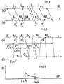
- Figure 2 presents a time diagram illustrating the transit of signals between a transmitter and a receiver of the network of Figure 1.
- Figure 3 presents a time diagram illustrating a comparison time performed in the receiver above.
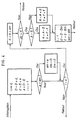
- Figure 4 shows an algorithm implemented in this receiver.
- Figure 5 shows a diagram showing, for each of the values possible transit delay of a signal in a transmission network asyncrhone, the probability density of the occurrence of this value.
- packets carrying information are transmitted by the network N from the transmitter E to the receiver R to carry out a communication in the frame of a telephone set.
- the calibration signals can be advantageously constituted by these packets, the moment marked by a such packet being for example a start defined by a header of this packet.
- Receiving intervals d 1. .... d i appear in this received sequence. Each of them, such as the interval d 1 , has a beginning such that M 1 consists of one of the instants of reception and an end such that M 2 constituted by the one of these instants which follows this beginning in this sequence. These reception times are marked on the axis 91 of FIGS. 2 and 3.
- the reception intervals are different from one another because the transmission network has subjected the timing signals to transit delays which have varied from one to another. random manner from one signal to another, each of these delays however being at least equal to a basic delay which is imposed by the structure of the network and by the positions of the transmitter and receiver relative thereto .
- the method further includes action steps for adjusting the frequency of the local clock, each of these stages constitutes a terminal step of a setting sequence also including a setting group of this step, this group including at least one said range of calculation.
- the calculation ranges of this group respectively constitute adjustment ranges, an offset A cumulative amount of this group consists of the algebraic sum of the these adjustment ranges.
- An action of this step brings to the frequency of the local clock a change in more or less depending on whether the shift cumulative amount of this group is negative or positive, respectively, so that accumulated offset is an error signal as mentioned above.
- this action and the amplitude of this particular changes are dependent on the previous adjustment steps and the absolute value of the cumulative offset so as to achieve a servo stable and preferably fast and accurate the theoretical interval to the interval of reference.
- This enslavement constitutes the enslavement mentioned above of the frequency of the local clock to that of the reference clock, or to this last frequency multiplied by a known predetermined number. Its stability, its speed and accuracy depend in particular on the choice of setting.
- the beginnings and ends of the adjustment ranges are then constituted only by adjustment terminals as defined as indicated above.
- the terminals B n-1 and B n limit such a range of duration Dm.
- This selection of the calculation ranges used to form the signal error has the advantage of suppressing, or at least greatly reducing, fluctuations in frequency that may result from certain variations in transit delays imposed on successive calibration signals. This benefit results the selective use of fast signals to determine the bounds of these beaches. It is a fact that has been recognized and exploited as part of this invention and which manifests itself when the search periods above are long enough. This fact is that the difference between the transit delays of two randomly selected signals are then made much weaker, in mean, when these two signals are selected from among the only fast signals if these signals had been selected from all the transmitted signals.
- the beginning such that M 1 of each of these periods such that P n is constituted by the end of the preceding period P n-1 .
- the search origin of this period is constituted by the control terminal B n-1 of a search period P n-1 preceding this period considered in the succession of search periods.
- a setting range then has its start and end respectively constituted by the two adjustment terminals B n-1 and B n of these two periods.
- the duration "k" of the successive search periods is adapted to the traffic network N. It can be constant. It can however be increased with advantage when it appears that the network N approaches a state of overload, this is because it is preferable that a calibration signal is selected only if its transit time only slightly exceeds the basic time limit. A signal having a such transit delay will be referred to as "sufficiently fast” below.
- the above advantage then results from the fact that on approaching the overload condition, Transit delays tend to deviate from the TTm base delay.
- increasing the duration "k” then makes it possible to find in each of the periods of search for such a fast enough signal despite the decrease in proportion of such signals in the set of calibration signals. If the charge the network N decreases later, the duration "k” is then reduced to a value of basis to avoid unnecessary lengthening of the fastening time required for bring the frequency of the local clock near the frequency of reference.
- a change in the frequency of the local clock could be performed after each adjustment range, this range then constituting to it only one setting group.
- the ranges of each adjustment group form a succession of ranges, the adjustment sequence including, for each adjustment range such as Dm of this group, the calculation of an offset cumulative A of this range.
- the cumulative offset of the first range of this succession is the "am" shift of this range and the accumulated shift of each of the following ranges is the algebraic sum of the shifts "am” of this next beach and beaches that preceded it.
- An error signal from The process is then constituted by the accumulated shift of a range of this group.
- control sequences also form a succession.
- the method then further includes a step of defining a tolerated offset domain, this domain extending between an offset threshold positive and a negative offset threshold typically having the same value absolute S. It also includes a step of defining a succession of increments of respective frequency f for the adjustment sequences.
- the modification of frequency mentioned above for each adjustment sequence is then only when the cumulative offset A of a range of the group of setting this sequence goes out of the range of tolerated shift, this modification having an amplitude equal to the frequency increment defined for this sequence.
- This beach is then a last beach of this group of setting.
- the magnitude and evolution of the frequency increment are determined to ensure the stability, speed and accuracy of the enslavement.
- the gap of local clock frequency can be large compared to the frequency of reference.
- the increment "f" then preferably has a high value compared to a basic increment "h” and it increases until a crossing of the reference frequency is detected. Every time that such a crossing has been detected this increment is decreased to be gradually reduced to the basic increment to ensure the stability of the enslavement.
- a frequency deviation manifests again this increment remains at first constant for a number of groups of setting giving the same direction of progression to the frequency F, then it grows to from a value equal to the basic increment multiplied by the same number, this until a new crossing is detected.
- Another object of this invention is a system for controlling a frequency via an asynchronous transmission network.
- This system puts into the process of the invention. It includes the receiver R and the clock local HR and this receiver includes a servo program to execute in essence the instructions summarized in the algorithm of Figure 4.
- the local clock HR is provided with a setting unit JR phase programmed to achieve a provisional phase agreement of this local clock with a time base outside this system thanks to a exchange of synchronization signals with this time base. This exchange is done via a means of transmission which imposes on these signals constant transit.
- the system of this invention then constitutes a system of synchronization to achieve a sustainable phase agreement through the frequency control described above.
- the time base is for example constituted by the clock HE of the emitter E, this clock being provided with a diffusion unit JE communicating with the JR unit.
- the transmission means is for example a radio channel.
- JR and JE units allow for initial phase agreement between the HE and HR clocks. They use for this antennas LE and LR respectively belonging to the transmitter E and the receiver R.
- the enslavement of frequency then allows to maintain this agreement with a precision acceptable at least for a period after which a new implementation phase is made by these units. This period can be made very long by the enslavement. The latter thus makes it possible not to clutter the radio channel above.
- the sequence of exchange of the synchronization signals between the units JE and JR may be analogous to that of the NTP protocol described in the publications RFC 1305 and RFC 1361. Such a sequence will be described with the understanding that each instant of transmission or reception a signal is defined using the clock of the unit that transmits or receives this signal: At a time H 0 not shown the unit I emits a first signal with a time stamp indicating this time. At one hour H 1 the unit JR receives this signal and, at one hour H 2 , it emits a second signal provided with time marks indicating the hours H 0 , H 1 and H 2 .
- the unit JR receives this third signal it sets the local clock HR so that the latter indicates for this moment the time H 4 + 1/2 RTD.
- Another subject of the invention is a radio telephone network including a plurality of base stations connected to one another via a asynchronous transmission network N.
- This network is characterized by the fact that at least one of these base stations constitutes a system as described above.
- the emitter E and the receiver R described above are constituted each by one of these base stations.
- the antennas LE and LR allow this transmitter and to this receiver to communicate with the mobile terminals of the network.
- each of the base stations constituting a receiver treats many communications, ie it receives, processes and issues various packets, the processing operations being able to include changes, routing etc ...
- This receiver therefore includes, for carry out these operations, a program which will be called hereinafter program main.
- this main program is interrupted to implement the servitude program mentioned above. Therefore, in Figure 4, the arrival point of such packets is designated by the word "interruption”.
- the word "return” it means a return to main program pending the arrival of the next package.
- Advantages of the invention appear in the case where the basis of such a network are quite close to one another so that the deadlines transmission of radio waves between the subscribers' mobile terminals and the base stations are almost negligible.
- a network local radiotelephone type European transmission network wireless DECT in which distances between stations are often included between 20 and 500 m and in which each station is provided with a clock of frame synchronization driven by a clock such as HE and HR and having a frequency of 100 Hz.
- the maintenance of a phase agreement between the clocks frame synchronization is then necessary to allow the transfer (hand over) a communication between two base stations during a moving a subscriber participating in this communication.
- This invention facilitates this transfer.
- this invention allows stabilize the frequency of the latter within a close delay of one or two minutes.
- the desired equality between the two frequencies is then reached with such accuracy that the time difference between the two clocks of frame synchronization can be maintained below 4,000 ns for a hold time such as two or three minutes.
- Such a delay allows, for quasi-periodic operations for the implementation of the phase agreement, easily find available time intervals between two telephone communications in a radio channel intended for such operations.
Landscapes
- Engineering & Computer Science (AREA)
- Theoretical Computer Science (AREA)
- General Engineering & Computer Science (AREA)
- Computer Networks & Wireless Communication (AREA)
- Signal Processing (AREA)
- Physics & Mathematics (AREA)
- Computer Hardware Design (AREA)
- General Physics & Mathematics (AREA)
- Multimedia (AREA)
- Synchronisation In Digital Transmission Systems (AREA)
- Mobile Radio Communication Systems (AREA)
- Radio Relay Systems (AREA)
- Transmitters (AREA)
- Transceivers (AREA)
- Data Exchanges In Wide-Area Networks (AREA)
Claims (11)
- Verfahren zur Regelung der Frequenz eines lokalen Taktgebers (HR) über ein asynchrones Übertragungsnetz (N), bestehend aus:wobei dieses Verfahren dadurch gekennzeichnet ist, dass die Festlegung der zeitlichen Verschiebungen die folgenden Schritte umfasst:einem Schritt zum Senden einer Folge von so genannten Einstellsignalen mit dem Takt einer Referenzfrequenz, die jeweils Zeitpunkte (L1... Li) markieren, wobei diese markierten Zeitpunkte in dieser gesendeten Folge durch aufeinander folgende Intervalle mit dem gleichen Wert voneinander getrennt sind, wobei dieser Wert ein Referenzintervall darstellt, wobei dieses Referenzintervall gleich einer vordefinierten Anzahl an Taktzeiten eines Sendetaktgebers (HE) ist,einem Schritt zur Übertragung der Einstellsignale über dieses asynchrone Übertragungsnetz, wobei diese Signale in diesem Netz mit unterschiedlichen Übertragungszeiträumen übertragen werden,einem Schritt zum Empfang einer Folge von Einstellsignalen am Ausgang des asynchronen Übertragungsnetzes, wobei die von diesen empfangenen Signale markierten Zeitpunkte Empfangszeitpunkte (M1 .. Mi) darstellen, die jeweils den von der Folge von Einstellsignalen markierten Zeitpunkten (L1 ... Li) entsprechen, wobei in dieser empfangenen Folge Empfangsintervalle (d1 ... di) vorhanden sind, die jeweils (d1) einen Anfang (M1), bestehend aus einem der genannten Empfangszeitpunkte, und ein Ende (M2) aufweisen, bestehend aus dem Empfangszeitraum, der in dieser Folge diesem Anfang folgt,einen Schritt zur Bestimmung der zeitlichen Verschiebungen (am), die jeweils den empfangenen Signalen zugeordnet werden, wobei jede dieser Verschiebungen zwischen zwei Zeitpunkten (Bn, Cn) auftritt, die sich entsprechen und von denen einer zu einer empfangenen Folge, die aus den jeweils durch diese empfangenen Signale markierten Zeitpunkten besteht, und der andere zu einer theoretischen Folge gehört, die durch den genannten lokalen Taktgeber (HR) definiert wird, wobei dieser Zeitpunkt der empfangenen Folge durch das genannte, dieser Verschiebung zugeordnete Signal markiert wird,einem Schritt zur Auswahl der empfangenen Signale, deren Übertragungszeiträume unter den empfangenen Signalen minimal sind, wobei ein empfangenes Signal ausgewählt wird, wenn es sich bei der diesem empfangenen Signal zugeordneten Verschiebung unter den einer Gruppe von aufeinander folgenden Zeitpunkten (Pn) zugeordneten Verschiebungen der genannten empfangenen Folge um eine minimale Verschiebung handelt, wobei dieser Auswahlschritt die Auswahl einer Abfolge von Suchtaktzeiten (Pn-1, Pn) umfasst, wobei jede dieser Taktzeiten einen Anfang und ein Ende aufweist, die durch eine gewählte Anzahl der genannten theoretischen Intervalle voneinander getrennt sind, wobei diese Anzahl über 3 liegt und die Dauer (k) dieser Taktzeit darstellt, wobei diese Taktzeit eine Abfolge von so genannten Empfangszeitpunkten umfasst, und die Suchschritte jeweils für die Suchtaktzeiten ausgeführt werden und jeweils die folgenden Schritte umfassen:Auswahl eines Suchanfangs, bestehend aus einem Zeitpunkt, der nicht nach dem Beginn dieser Taktzeit liegt,Berechnung der diesem Zeitpunkt zugeordneten Verschiebung für jeden der genannten Empfangszeitpunkte dieser Taktzeit, wobei diese Verschiebung der genannten Verschiebung des genannten Berechnungsbereichs entspricht, mit einem Anfang, entsprechend diesem Suchanfang, und einem Ende entsprechend diesem Zeitpunkt, undDefinition einer Einstellgrenze (Bn), wobei diese Grenze durch einen der genannten Empfangszeitpunkte dieser Taktzeit dargestellt wird und so gestaltet ist, dass es sich bei der genannten, dieser Grenze zugeordneten Verschiebung (am) um die kleinste der diesen Zeitpunkten zugeordneten Verschiebungen handelt, wobei die genannten Anfänge und Enden der genannten Einstellbereiche (Dm) durch die genannten Einstellgrenzen (Bn-1 und Bn) dargestellt werden,einem Schritt zur Erstellung eines Fehlersignals ausgehend von den gewählten Signalen,einem Schritt zur Rückkopplung der Frequenz des lokalen Taktgebers (HR) mit der Referenzfrequenz mit Hilfe dieses Fehlersignals;sowie dadurch, dass der Schritt zur Erstellung des genannten Fehlersignals ausgehend von den ausgewählten Signalen, für jeden Berechnungsbereich beinhaltet:einen Schritt zur Auswahl eines theoretischen Intervalls (e), das in Bezug auf die Taktzeit dieses lokalen Taktgebers (HR) definiert wird und das der Dauer des Referenzintervalls so nah wie möglich kommt,einen Schritt, bestehend aus einer Abfolge von Einsätzen dieses lokalen Taktgebers (HR), um einen Messwert für jedes der genannten Empfangsintervalle zu liefern, wobei dieser Wert ein Messintervall darstellt, das zum Ende dieses Intervalls endet,einen Schritt zur Definition einer Vielzahl an Berechnungsbereichen, wobei jeder dieser Bereiche einen Anfang und ein Ende aufweist, die jeweils von zwei der genannten Empfangszeitpunkte dargestellt werden,und Schritte, die für jeden der genannten Berechnungsbereiche ausgeführt werden, wobei diese Schritte mindestens die- Folgenden umfassen:einen Schritt zur Addition der genannten Messintervalle, die innerhalb dieses Bereichs enden, wobei das Ergebnis dieser Addition ein kumuliertes Messintervall (D) dieses Bereichs darstellt, wobei die Anzahl dieser Intervalle die Anzahl an Intervallen dieses Bereichs darstellt,einen Schritt zur Multiplikation des genannten theoretischen Intervalls (e) mit der genannten Anzahl an Intervallen dieses Bereichs, wobei das Ergebnis dieser Multiplikation ein kumuliertes theoretisches Intervall (E) dieses Bereichs darstellt, undeinen Schritt zur Berechnung einer Verschiebung (a) dieses Bereichs, wobei diese Verschiebung einen algebraischen Wert (D - E) aufweist, der dem genannten kumulierten Messintervall dieses Bereichs, abzüglich dem genannten kumulierten theoretischen Intervall dieses Bereichs entspricht;einen Schritt zur Berechnung der kumulierten Verschiebung (A) dieses Berechnungsbereichs, wobei die genannte kumulierte Verschiebung des genannten ersten Bereichs die genannte Verschiebung (am) dieses Bereichs darstellt, wobei die genannte kumulierte Verschiebung jedes der genannten folgenden Bereiche der algebraischen Summe der genannten Verschiebungen (am) dieses folgenden Bereichs und der diesem Bereich vorhergehenden Bereiche in der genannten Abfolge der Bereiche entspricht,und einen Schritt zur Erstellung eines Fehlersignals, bestehend aus der genannten kumulierten Verschiebung eines Bereichs dieser Abfolge von Berechnungsbereichen.
- Verfahren gemäß Anspruch 1, wobei dieses Verfahren durch die Tatsache gekennzeichnet ist, dass es außerdem Schritte zur Einstellung der Frequenz des genannten lokalen Taktgebers beinhaltet, wobei jeder dieser Schritte den Abschlussschritt einer Einstellsequenz darstellt, die auch eine Gruppe zur Einstellung dieses Schritts umfasst, wobei diese Gruppe mindestens einen genannten Berechnungsbereich beinhaltet, wobei die Berechnungsbereiche dieser Gruppe jeweils Einstellbereiche darstellen, wobei die kumulierte Verschiebung (A) dieser Gruppe jeweils durch die algebraische Summe der genannten Verschiebungen dieser Einstellbereiche dargestellt wird, wobei ein Vorgang dieses Schritts die Frequenz des genannten lokalen Taktgebers (HR) erhöht oder verringert, je nachdem, ob die genannte kumulierte Verschiebung dieser Gruppe negativ oder positiv ist, so dass diese kumulierte Verschiebung das genannte Fehlersignal darstellt.
- Verfahren gemäß Anspruch 2, wobei dieses Verfahren durch die Tatsache gekennzeichnet ist, dass der Anfang (M1) jeder dieser Taktzeiten (Pn) in der genannten Abfolge von Suchtaktzeiten durch das Ende der vorhergehenden Taktzeit (Pn-1) dargestellt wird.
- Verfahren gemäß Anspruch 3, wobei dieses Verfahren durch die Tatsache gekennzeichnet ist, dass für jede genannte Suchtaktzeit, die eine bestimmte Taktzeit (Pn) darstellt, der genannte Suchanfang dieser Taktzeit durch die genannte Einstellgrenze (Bn-1) einer Suchtaktzeit (Pn-1) dargestellt wird, die dieser bestimmten Taktzeit in der Abfolge der Suchtaktzeiten vorangeht, wobei der genannte Einstellbereich einen Anfang und ein Ende aufweist, die jeweils durch die beiden genannten Einstellgrenzen (Bn-1, Bn) dieser beiden Taktzeiten dargestellt werden.
- Verfahren gemäß Anspruch 4, wobei die genannten Dauer (k) der Suchtaktzeiten zwischen 10 und 10 000 beträgt.
- Verfahren gemäß Anspruch 1, wobei die genannten Einstellsequenzen eine Abfolge von Sequenzen bilden und dieses Verfahren außerdem die folgenden Schritte umfasst:Definition eines tolerierten Verschiebungsbereichs zwischen einem positiven Verschiebungsgrenzwert (S) und einem negativen Verschiebungsgrenzwert (-S), undDefinition einer Abfolge von Frequenzinkrementen (f) für die genannten Einstellsequenzen, wobei die genannte Frequenzänderung der genannten Einstellsequenz nur vorgenommen wird, wenn die genannte kumulierte Verschiebung (A) des Bereichs der genannten Einstellgruppe dieser Sequenz den genannten tolerierten Einstellbereich überschreitet, wobei diese Änderung eine Amplitude aufweist, die dem genannten Frequenzinkrement (f) entspricht, das für diese Sequenz definiert wurde, wobei dieser Bereich dann den letzten Bereich dieser Einstellgruppe darstellt.
- System zur Regelung der Frequenz eines lokalen Taktgebers (HR) über ein asynchrones Übertragungsnetz (N), bestehend aus:wobei dieses System dadurch gekennzeichnet ist, dass die Vorrichtungen zur Bestimmung der zeitlichen Abweichungen umfassen:Vorrichtungen zum Senden einer Folge von so genannten Einstellsignalen mit dem Takt einer Referenzfrequenz, die jeweils Zeitpunkte (L1... Li) markieren, wobei diese markierten Zeitpunkte in dieser gesandten Folge durch aufeinander folgende Intervalle mit dem gleichen Wert voneinander getrennt sind, wobei dieser Wert ein Referenzintervall darstellt, wobei dieses Referenzintervall gleich einer vordefinierten Anzahl an Taktzeiten eines Sendetaktgebers (HE) ist,Vorrichtungen zur Übertragung der Einstellsignale über dieses asynchrone Übertragungsnetz, wobei diese Signale mit unterschiedlichen Übertragungszeiträumen über dieses Netz übertragen werden,Vorrichtungen zum Empfang einer Folge von Einstellsignalen am Ausgang des asynchronen Übertragungsnetzes, wobei die von diesen empfangenen Signalen markierten Zeitpunkte Empfangszeitpunkte (M1 ... Mi) darstellen, die jeweils den von der Folge von Einstellsignalen markierten Zeitpunkten (L1 ... Li) entsprechen, wobei in dieser empfangenen Folge Empfangsintervalle (d1 ... di) vorhanden sind, die jeweils (d1) einen Anfang (M1), bestehend aus einem der genannten Empfangszeitpunkte, und ein Ende (M2) aufweisen, bestehend aus dem Empfangszeitraum, der in dieser Folge diesem Anfang folgt,Vorrichtungen zur Ermittlung der zeitlichen Verschiebungen (am), die den empfangenen Signalen zugeordnet werden, wobei jede dieser Verschiebungen zwischen zwei Zeitpunkten (Bn, Cn) auftritt, die sich entsprechen und von denen einer zu einer empfangenen Folge von Zeitpunkten, die jeweils von diesen empfangenen Signalen markiert werden, und der andere zu einer theoretischen Folge gehört, die durch den genannten lokalen Taktgeber (HR) definiert wird, wobei dieser Zeitpunkt der empfangenen Folge durch das genannte, dieser Verschiebung zugeordnete Signal markiert wird,Vorrichtungen zur Auswahl der empfangenen Signale, deren Übertragungszeiträume unter den empfangenen Signalen minimal sind, wobei ein empfangenes Signal ausgewählt wird, wenn die genannte, diesem empfangenen Signal zugeordnete Verschiebung unter den einer Gruppe von aufeinander folgenden Zeitpunkten (Pn) der genannten empfangenen Folge zugeordneten Verschiebungen eine minimale Verschiebung aufweist, wobei dieser Auswahlschritt die Auswahl einer Abfolge von Suchtaktzeiten (Pn-1, Pn) umfasst, wobei jede dieser Taktzeiten einen Anfang und ein Ende aufweist, die durch eine bestimmte Anzahl an genannten theoretischen Intervallen voneinander getrennt sind, wobei diese Anzahl größer ist als drei und die Dauer (k) dieser Taktzeit darstellt, wobei diese Taktzeit eine Abfolge der genannten Empfangszeitpunkte umfasst,und Suchvorrichtungen, bestehend aus:Vorrichtungen zur Auswahl eines Suchanfangs, dargestellt durch einen Zeitpunkt, der nicht nach dem Anfang dieser Taktzeit liegt,Rechenvorrichtungen zur Berechnung einer diesem Zeitpunkt zugeordneten Verschiebung für jeden der genannten Empfangszeitpunkte dieser Taktzeit, wobei es sich bei dieser Verschiebung um die Verschiebung des genannten Berechnungsbereiches handelt, mit einem Anfang, dargestellt durch diesen Suchanfang, und einem Ende, dargestellt durch diesen Zeitpunkt, undVorrichtungen zur Definition einer Einstellgrenze (Bn), wobei diese Grenze aus einem der genannten Empfangszeitpunkte dieser Taktzeit besteht und so gestaltet ist, dass die genannte Verschiebung (am), die dieser Grenze zugeordnet ist, die kleinste der diesen Zeitpunkten zugeordneten genannten Verschiebungen ist, wobei die genannten Anfänge und Enden der genannten Einstellbereiche (Dm) durch die genannten Einstellgrenzen (Bn-1 und Bn) dargestellt werden,Vorrichtungen zur Erstellung eines Fehlersignals, ausgehend von den ausgewählten Signalen,und Vorrichtungen zur Rückkopplung der Frequenz eines lokalen Taktgebers (HR) mit der Referenzfrequenz mit Hilfe dieses Fehlersignals;wobei das Ergebnis dieser Addition ein kumuliertes Messintervall (D) dieses Bereichs darstellt, wobei die Anzahl dieser Intervalle die Anzahl der Intervalle dieses Bereichs darstellt,Vorrichtungen zur Auswahl eines theoretischen Intervalls (e), das in Bezug auf die Taktzeit dieses lokalen Taktgebers (HR) definiert wird und der Dauer des Referenzintervalls so nah wie möglich kommt,Vorrichtungen zur Lieferung eines Messwerts für jedes der genannten Empfangsintervalle unter Verwendung dieses lokalen Taktgebers (HR), wobei dieser Wert ein Messintervall darstellt, das zum genannten Ende dieses Intervalls endet,Vorrichtungen zur Definition einer Vielzahl an Berechnungsbereichen, wobei jeder diese Bereiche einen Anfang und ein Ende aufweist, die jeweils durch zwei der genannten Empfangszeitpunkte dargestellt werden, wobei diese Vorrichtungen umfassen:Vorrichtungen zur Addition der genannten Messintervalle, die innerhalb dieses Bereichs enden,sowie dadurch, dass die Vorrichtungen zur Erstellung des genannten Fehlersignals ausgehend von den ausgewählten Signalen für jeden Messbereich beinhalten:Vorrichtungen zur Multiplikation des genannten theoretischen Intervalls (e) mit der genannten Anzahl an Intervallen dieses Bereichs, wobei das Ergebnis dieser Multiplikation das kumulierte theoretische Intervall (E) dieses Bereichs darstellt, undVorrichtungen zur Berechnung der Verschiebung (a) dieses Bereichs mit einem algebraischen Wert (D - E) gleich dem genannten kumulierten Messintervall dieses Bereichs abzüglich des genannten kumulierten theoretischen Intervalls dieses Bereichs;Vorrichtungen zur Berechnung der kumulierten Verschiebung (A) dieses Berechnungsbereichs, wobei die genannte kumulierte Verschiebung des genannten ersten Bereichs die genannte Verschiebung (am) dieses Bereichs darstellt, wobei die kumulierte Verschiebung jedes der genannten folgenden Bereiche die algebraische Summe der genannten Verschiebungen (am) dieses folgenden Bereichs und der diesem Bereich vorausgehenden Bereiche in der genannten Abfolge der Bereiche darstellt,und Vorrichtungen zur Erstellung eines Fehlersignals, dargestellt von der genannten kumulierten Verschiebung eines Bereichs dieser Abfolge von Berechnungsbereichen.
- System gemäß Anspruch 7, wobei der genannte Empfänger (R) beinhaltet:Vorrichtungen zum Auslesen des Intervalls Di, das zwischen diesem Empfangszeitpunkt (Mi+1) und dem vorhergehenden Empfangszeitpunkt (Mi) in der genannten Empfangsfolge gemessen wird, wobei i ein Index ist, der für den ersten Empfangszeitpunkt nach Beginn jeder so genannten Suchtaktzeit den Wert 1 aufweist,Vorrichtungen zur Ausführung von D = D + di, wobei D das genannte kumulierte Messintervall eines Berechnungsbereichs innerhalb dieser Taktzeit darstellt,Vorrichtungen zur Ausführung von E = E + e, wobei E das genannte kumulierte theoretische Intervall und e das genannte theoretische Intervall darstellt,Vorrichtungen zur Ausführung von a = D - E, wobei a die genannte Verschiebung dieses Bereichs darstellt,Vorrichtungen zur Ausführung von i = i + 1,Vorrichtungen zur Beantwortung der Frage a<am?, wobei am eine Größe ist, die so lange weiter ansteigt, bis sie die genannte Verschiebung aufweist, die der Berechnungsgrenze zugeordnet ist,Vorrichtungen zur Ausführung, wenn die Antwort auf die Frage a<am? "ja" lautet, von:am = a,Dm = D, wobei Dm von den nachfolgenden Anweisungen definiert wird.und Em = E,Vorrichtungen zur Beantwortung der Frage i = k?, wobei k die genannte Dauer dieser Suchtaktzeit darstellt, unabhängig von der Antwort auf die Frage a<am?, undVorrichtungen zum Abwarten des nächsten Empfangszeitpunkts, wenn die Antwort auf die Frage i = k? "nein" lautet;Vorrichtungen, die, falls die Antwort auf die Frage i = k? "ja" lautet und falls außerdem ein genannter Vorgang dem genannten Programm entspricht, diesen Vorgang ausführen, und Ausführung von:i = 1,D = D - Dm,E = E - Em,am = aM, wobei aM eine vordefinierte Größe ist, die mindestens dem größten vorhersehbaren Wert einer dem Empfangszeitpunkt zugeordneten genannten Verschiebung entspricht,und Abwarten des nächsten Empfangszeitpunkts.
- System gemäß Anspruch 8, das außerdem ein Inkrementrechenwerk (G) umfasst, um das genannte Frequenzinkrement zu berechnen, wobei dieses Rechenwerk Informationen von dem genannten Empfänger (R) enthält und die Informationen an den genannten lokalen Taktgeber (HR) weiterleitet, wobei das genannte Rechenwerk umfasst:Vorrichtungen zur Ausführung von A = A + am, wobei A eine variable Größe ist, die bei Inbetriebnahme dieses Systems den Wert Null aufweist,Vorrichtungen zur Beantwortung der Frage IAI > S?, wobei S einen absoluten Wert darstellt, der für den genannten positiven und negativen Abweichungsgrenzwert gleich ist,Vorrichtungen zum Abwarten des nächsten Empfangszeitpunkts, wenn die Antwort auf die Frage IAI >S? "nein" lautet,Vorrichtungen zur Beantwortung der Frage A>S?, wenn die Antwort auf die Frage IAI>S? "ja" lautet,Vorrichtungen, falls die Antwort auf die Frage A>S? "nein" lautet, zur:Ausführung von A = A + SUmsetzung der genannten Änderung F = F + f, wobei F die Frequenz des genannten lokalen Taktgebers und f das genannte Frequenzinkrement darstellt, wobei jede genannte Änderung anhand eines Befehls dieses genannten Taktgebers durch den genannten Empfänger mit Hilfe des genannten Inkrementrechenwerks G ausgeführt wird,Übermittlung der Informationen über die vorhergehende Änderung an das Rechenwerk G,Vorrichtungen, falls die Antwort auf die Frage A>S? "ja" lautet, zur:Ausführung von A = A - S,Umsetzung der genannten Änderung F = F - f, undÜbermittlung der Informationen über die vorhergehende Änderung an das Rechenwerk G.
- System gemäß einem der Ansprüche 7 bis 9, wobei der genannte lokale Taktgeber (HR) mit einer Phasenregelungsvorrichtung (JR) ausgerüstet ist, die entsprechend programmiert ist, um einen provisorischen Phasenabgleich zwischen diesem lokalen Taktgeber und einer Zeitbasis (HE, JE) außerhalb des Systems auszuführen, der anhand des Austauschs von Synchronisationssignalen mit dieser Zeitbasis durchgeführt wird, wobei dieser Austausch über eine Übertragungsvorrichtung erfolgt, die diesen Signalen konstante Übertragungszeiträume vorgibt.
- Sprechfunknetz, das eine Vielzahl an Basisstationen beinhaltet, die über ein asynchrones Übertragungsnetz (N) miteinander verbunden sind, wobei dieses System durch die Tatsache gekennzeichnet ist, dass mindestens eine dieser Basisstationen ein System gemäß einem der Ansprüche 8 bis 10 darstellt.
Applications Claiming Priority (2)
| Application Number | Priority Date | Filing Date | Title |
|---|---|---|---|
| FR9815273 | 1998-12-03 | ||
| FR9815273A FR2786964B1 (fr) | 1998-12-03 | 1998-12-03 | Procede et systeme pour asservir une frequence via un reseau de transmission asynchrone et reseau radiotelephonique incluant ce systeme |
Publications (2)
| Publication Number | Publication Date |
|---|---|
| EP1006686A1 EP1006686A1 (de) | 2000-06-07 |
| EP1006686B1 true EP1006686B1 (de) | 2005-08-24 |
Family
ID=9533538
Family Applications (1)
| Application Number | Title | Priority Date | Filing Date |
|---|---|---|---|
| EP99402641A Expired - Lifetime EP1006686B1 (de) | 1998-12-03 | 1999-10-25 | Verfahren und Vorrichtung zur Steuerung einer Frequenz durch ein asynchrones Übertragungsnetzwerk und Funktelefonienetzwerk, das die Vorrichtung verwendet |
Country Status (6)
| Country | Link |
|---|---|
| US (1) | US6819685B1 (de) |
| EP (1) | EP1006686B1 (de) |
| JP (1) | JP2000174821A (de) |
| AT (1) | ATE303022T1 (de) |
| DE (1) | DE69926857T2 (de) |
| FR (1) | FR2786964B1 (de) |
Cited By (1)
| Publication number | Priority date | Publication date | Assignee | Title |
|---|---|---|---|---|
| WO2012058912A1 (zh) * | 2010-11-01 | 2012-05-10 | 中兴通讯股份有限公司 | 时间同步方法及节点 |
Families Citing this family (17)
| Publication number | Priority date | Publication date | Assignee | Title |
|---|---|---|---|---|
| FI115494B (fi) | 1999-09-08 | 2005-05-13 | Nokia Corp | Tukiaseman taajuussynkronointi |
| US7020791B1 (en) * | 2002-09-19 | 2006-03-28 | Nortel Networks Limited | Clock recovery using a double-exponential smoothing process |
| US7555017B2 (en) | 2002-12-17 | 2009-06-30 | Tls Corporation | Low latency digital audio over packet switched networks |
| GB2399263A (en) * | 2003-03-07 | 2004-09-08 | Zarlink Semiconductor Ltd | Clock synchronisation over a packet network |
| GB2400255A (en) | 2003-03-31 | 2004-10-06 | Sony Uk Ltd | Video synchronisation |
| DE10326336B4 (de) * | 2003-06-11 | 2006-06-29 | Infineon Technologies Ag | Vorrichtung und Verfahren zum zeitlichen Steuern der Verarbeitung eines Funksignals in einer Mobilstation |
| US6977615B2 (en) * | 2004-03-04 | 2005-12-20 | Omron Automotive Electronics, Inc. | Microstrip antenna for RF receiver |
| EP2026485A1 (de) * | 2007-08-17 | 2009-02-18 | Nokia Siemens Networks Oy | Verfahren und Vorrichtung zur paketbasierten Taktwiederherstellung |
| US8272600B2 (en) | 2008-06-09 | 2012-09-25 | Workrite Ergonomics, Inc. | Keyboard and mouse support |
| CN101674174B (zh) * | 2008-09-12 | 2013-06-05 | 华为技术有限公司 | 一种提高时钟稳定度的方法及设备 |
| GB2489002A (en) * | 2011-03-14 | 2012-09-19 | Nujira Ltd | Delay adjustment to reduce distortion in an envelope tracking transmitter |
| CN102412954B (zh) * | 2011-11-19 | 2014-10-22 | 西安邮电学院 | 一种分组网中时钟频率同步方法 |
| CN105892560A (zh) * | 2016-03-29 | 2016-08-24 | 杭州和利时自动化有限公司 | 一种用于嵌入式系统的时钟检测方法及系统 |
| WO2020165979A1 (ja) * | 2019-02-13 | 2020-08-20 | 株式会社Nttドコモ | 無線基地局及びユーザ装置 |
| CN110196997B (zh) * | 2019-04-30 | 2024-04-26 | 中国电力科学研究院有限公司 | 一种电磁暂态异步并行计算方法及装置 |
| CN112116919B (zh) * | 2019-06-19 | 2024-06-04 | 杭州海康威视数字技术股份有限公司 | 一种回声消除方法、装置及电子设备 |
| CN119232308B (zh) * | 2024-12-04 | 2025-03-07 | 江苏瑞电智芯信息科技有限公司 | 基于降采样特征序列最大匹配的低压台区终端对时方法 |
Family Cites Families (8)
| Publication number | Priority date | Publication date | Assignee | Title |
|---|---|---|---|---|
| US5396492A (en) * | 1993-04-28 | 1995-03-07 | At&T Corp. | Method and apparatus for adaptive clock recovery |
| US5450394A (en) * | 1994-03-10 | 1995-09-12 | Northern Telecom Limited | Delay monitoring of telecommunication networks |
| GB9410943D0 (en) | 1994-06-01 | 1994-07-20 | Newbridge Networks Corp | Clock recovery unit |
| US5608731A (en) * | 1995-03-31 | 1997-03-04 | Transwitch Corporation | Closed loop clock recovery for synchronous residual time stamp |
| US5742594A (en) * | 1996-06-13 | 1998-04-21 | Motorola, Inc. | Method and apparatus for allocating shared bandwidth among a plurality of users |
| CA2184517A1 (en) * | 1996-08-30 | 1998-03-01 | Randy A. Law | Clock recovery for video communication over atm network |
| DE19644238C2 (de) * | 1996-10-24 | 1998-12-24 | Krone Ag | Verfahren zur Synchronisation von Übertragungen mit konstanter Bitrate in ATM-Netzen und Schaltungsanordnung zur Durchführung des Verfahrens |
| CA2202307A1 (en) * | 1997-04-10 | 1998-10-10 | Newbridge Networks Corporation | Generation of primary rate clocks from correction values derived from the received synchronous residual time stamp |
-
1998
- 1998-12-03 FR FR9815273A patent/FR2786964B1/fr not_active Expired - Fee Related
-
1999
- 1999-10-25 DE DE69926857T patent/DE69926857T2/de not_active Expired - Lifetime
- 1999-10-25 EP EP99402641A patent/EP1006686B1/de not_active Expired - Lifetime
- 1999-10-25 AT AT99402641T patent/ATE303022T1/de not_active IP Right Cessation
- 1999-11-19 US US09/443,463 patent/US6819685B1/en not_active Expired - Lifetime
- 1999-12-02 JP JP11343950A patent/JP2000174821A/ja active Pending
Cited By (1)
| Publication number | Priority date | Publication date | Assignee | Title |
|---|---|---|---|---|
| WO2012058912A1 (zh) * | 2010-11-01 | 2012-05-10 | 中兴通讯股份有限公司 | 时间同步方法及节点 |
Also Published As
| Publication number | Publication date |
|---|---|
| FR2786964A1 (fr) | 2000-06-09 |
| DE69926857D1 (de) | 2005-09-29 |
| EP1006686A1 (de) | 2000-06-07 |
| DE69926857T2 (de) | 2006-06-08 |
| FR2786964B1 (fr) | 2001-01-05 |
| ATE303022T1 (de) | 2005-09-15 |
| US6819685B1 (en) | 2004-11-16 |
| JP2000174821A (ja) | 2000-06-23 |
Similar Documents
| Publication | Publication Date | Title |
|---|---|---|
| EP1006686B1 (de) | Verfahren und Vorrichtung zur Steuerung einer Frequenz durch ein asynchrones Übertragungsnetzwerk und Funktelefonienetzwerk, das die Vorrichtung verwendet | |
| EP0487428B1 (de) | Anordnung für synchrone Informationsübertragung über ein asynchrones Netzwerk, insbesondere über ein ATM-Netzwerk | |
| EP2149214B1 (de) | Phasensynchronisierung von knoten in einem nachrichtenübertragungsnetz | |
| EP0041429B1 (de) | Verfahren und Einrichtung zur Synchronisierung digitaler Signale | |
| FR2750000A1 (fr) | Commande de la puissance de transmission dans le transfert sans fil de donnees par paquets | |
| EP0616443A2 (de) | Telekommunikationssystem mit Abstandsmessung | |
| EP1145477A1 (de) | Verfahren und vorrichtung zur synchronisierung | |
| FR2899045A1 (fr) | Source de synchronisation | |
| FR2899049A1 (fr) | Source de synchronisation | |
| FR2800222A1 (fr) | Procede de mise en conformite a un contrat de trafic d'un flux de paquets d'un reseau de transport de paquets a longueur variable | |
| FR2670974A1 (fr) | Dispositif pour la transmission par un reseau asynchrone, notamment un reseau de type atm, de donnees de signalisation voie par voie regroupees dans une multitrame emise de maniere synchrone en mode hors bande. | |
| EP2566077A1 (de) | Kommunikationssystem zur Übertragung von Signalen zwischen Endgeräten, die an Zwischengeräte angeschlossen sind, die mit einem Ethernetnetz verbunden sind | |
| WO1993007694A1 (fr) | Procede d'allocation de ressources par reservation anticipee dans un reseau satellite a integration de services | |
| EP0277380B1 (de) | Verfahren zur Verzögerungsregelung zwischen TDMA-Informationsübertragungsstationen und System wozu das Verfahren durchgeführt wird | |
| CA2158895C (fr) | Reseau de transmission point a multipoint a acces multiples par repartition temporelle | |
| FR2662887A1 (fr) | Procede pour reduire la composante basse-frequence de la gigue dans un systeme de transmission de donnees numeriques. | |
| FR2711435A1 (fr) | Dispositif pour justifier à intervalles réguliers un train numérique. | |
| FR2658969A1 (fr) | Systeme constitue en reseau tel qu'un systeme radiotelephonique cellulaire, permettant de mesurer le retard de transmission entre nóoeuds du reseau et de les synchroniser entre eux. | |
| EP3231099B1 (de) | Synchronisierung eines plc-netzwerks | |
| FR2879058A1 (fr) | Systeme adaptatif de recuperation d'horloge | |
| EP0779002B1 (de) | Verfahren zur bewahrung der zeitsynchronisation einer mobilstation in einem digitalen zellularen funknachrichtenübertragungssystem | |
| EP1071229B1 (de) | Verfahren zur Kommunikationsübertragung durch zwei digitale Telefonnetzwerke | |
| EP4576788A1 (de) | Verfahren und vorrichtung zur aktualisierung einer ausgabezeit mindestens eines datenpakets eines audiovisuellen datenstroms | |
| EP0465300B1 (de) | Verfahren zur Regelung der Sendeleistung von Endstationen in einem Zeitgetrenntlage-Übertragungsnetzwerk | |
| EP3652904A1 (de) | Paketbasierte kommunikation |
Legal Events
| Date | Code | Title | Description |
|---|---|---|---|
| PUAI | Public reference made under article 153(3) epc to a published international application that has entered the european phase |
Free format text: ORIGINAL CODE: 0009012 |
|
| AK | Designated contracting states |
Kind code of ref document: A1 Designated state(s): AT BE CH CY DE DK ES FI FR GB GR IE IT LI LU MC NL PT SE |
|
| AX | Request for extension of the european patent |
Free format text: AL;LT;LV;MK;RO;SI |
|
| 17P | Request for examination filed |
Effective date: 20001207 |
|
| AKX | Designation fees paid |
Free format text: AT BE CH CY DE DK ES FI FR GB GR IE IT LI LU MC NL PT SE |
|
| TPAC | Observations filed by third parties |
Free format text: ORIGINAL CODE: EPIDOSNTIPA |
|
| 17Q | First examination report despatched |
Effective date: 20040730 |
|
| GRAP | Despatch of communication of intention to grant a patent |
Free format text: ORIGINAL CODE: EPIDOSNIGR1 |
|
| GRAS | Grant fee paid |
Free format text: ORIGINAL CODE: EPIDOSNIGR3 |
|
| GRAA | (expected) grant |
Free format text: ORIGINAL CODE: 0009210 |
|
| AK | Designated contracting states |
Kind code of ref document: B1 Designated state(s): AT BE CH CY DE DK ES FI FR GB GR IE IT LI LU MC NL PT SE |
|
| PG25 | Lapsed in a contracting state [announced via postgrant information from national office to epo] |
Ref country code: NL Free format text: LAPSE BECAUSE OF FAILURE TO SUBMIT A TRANSLATION OF THE DESCRIPTION OR TO PAY THE FEE WITHIN THE PRESCRIBED TIME-LIMIT Effective date: 20050824 Ref country code: IE Free format text: LAPSE BECAUSE OF FAILURE TO SUBMIT A TRANSLATION OF THE DESCRIPTION OR TO PAY THE FEE WITHIN THE PRESCRIBED TIME-LIMIT Effective date: 20050824 Ref country code: FI Free format text: LAPSE BECAUSE OF FAILURE TO SUBMIT A TRANSLATION OF THE DESCRIPTION OR TO PAY THE FEE WITHIN THE PRESCRIBED TIME-LIMIT Effective date: 20050824 Ref country code: AT Free format text: LAPSE BECAUSE OF FAILURE TO SUBMIT A TRANSLATION OF THE DESCRIPTION OR TO PAY THE FEE WITHIN THE PRESCRIBED TIME-LIMIT Effective date: 20050824 |
|
| REG | Reference to a national code |
Ref country code: GB Ref legal event code: FG4D Free format text: NOT ENGLISH |
|
| REG | Reference to a national code |
Ref country code: CH Ref legal event code: EP |
|
| REG | Reference to a national code |
Ref country code: IE Ref legal event code: FG4D Free format text: LANGUAGE OF EP DOCUMENT: FRENCH |
|
| REF | Corresponds to: |
Ref document number: 69926857 Country of ref document: DE Date of ref document: 20050929 Kind code of ref document: P |
|
| PG25 | Lapsed in a contracting state [announced via postgrant information from national office to epo] |
Ref country code: CY Free format text: LAPSE BECAUSE OF FAILURE TO SUBMIT A TRANSLATION OF THE DESCRIPTION OR TO PAY THE FEE WITHIN THE PRESCRIBED TIME-LIMIT Effective date: 20051025 |
|
| PG25 | Lapsed in a contracting state [announced via postgrant information from national office to epo] |
Ref country code: MC Free format text: LAPSE BECAUSE OF NON-PAYMENT OF DUE FEES Effective date: 20051031 Ref country code: LU Free format text: LAPSE BECAUSE OF NON-PAYMENT OF DUE FEES Effective date: 20051031 Ref country code: LI Free format text: LAPSE BECAUSE OF NON-PAYMENT OF DUE FEES Effective date: 20051031 Ref country code: CH Free format text: LAPSE BECAUSE OF NON-PAYMENT OF DUE FEES Effective date: 20051031 Ref country code: BE Free format text: LAPSE BECAUSE OF NON-PAYMENT OF DUE FEES Effective date: 20051031 |
|
| GBT | Gb: translation of ep patent filed (gb section 77(6)(a)/1977) |
Effective date: 20051010 |
|
| PG25 | Lapsed in a contracting state [announced via postgrant information from national office to epo] |
Ref country code: SE Free format text: LAPSE BECAUSE OF FAILURE TO SUBMIT A TRANSLATION OF THE DESCRIPTION OR TO PAY THE FEE WITHIN THE PRESCRIBED TIME-LIMIT Effective date: 20051124 Ref country code: GR Free format text: LAPSE BECAUSE OF FAILURE TO SUBMIT A TRANSLATION OF THE DESCRIPTION OR TO PAY THE FEE WITHIN THE PRESCRIBED TIME-LIMIT Effective date: 20051124 Ref country code: DK Free format text: LAPSE BECAUSE OF FAILURE TO SUBMIT A TRANSLATION OF THE DESCRIPTION OR TO PAY THE FEE WITHIN THE PRESCRIBED TIME-LIMIT Effective date: 20051124 |
|
| PG25 | Lapsed in a contracting state [announced via postgrant information from national office to epo] |
Ref country code: ES Free format text: LAPSE BECAUSE OF FAILURE TO SUBMIT A TRANSLATION OF THE DESCRIPTION OR TO PAY THE FEE WITHIN THE PRESCRIBED TIME-LIMIT Effective date: 20051205 |
|
| PG25 | Lapsed in a contracting state [announced via postgrant information from national office to epo] |
Ref country code: PT Free format text: LAPSE BECAUSE OF FAILURE TO SUBMIT A TRANSLATION OF THE DESCRIPTION OR TO PAY THE FEE WITHIN THE PRESCRIBED TIME-LIMIT Effective date: 20060124 |
|
| NLV1 | Nl: lapsed or annulled due to failure to fulfill the requirements of art. 29p and 29m of the patents act | ||
| REG | Reference to a national code |
Ref country code: IE Ref legal event code: FD4D |
|
| REG | Reference to a national code |
Ref country code: CH Ref legal event code: PL |
|
| PLBE | No opposition filed within time limit |
Free format text: ORIGINAL CODE: 0009261 |
|
| STAA | Information on the status of an ep patent application or granted ep patent |
Free format text: STATUS: NO OPPOSITION FILED WITHIN TIME LIMIT |
|
| 26N | No opposition filed |
Effective date: 20060526 |
|
| REG | Reference to a national code |
Ref country code: FR Ref legal event code: CD |
|
| BERE | Be: lapsed |
Owner name: ALCATEL Effective date: 20051031 |
|
| PGFP | Annual fee paid to national office [announced via postgrant information from national office to epo] |
Ref country code: IT Payment date: 20101025 Year of fee payment: 12 |
|
| PG25 | Lapsed in a contracting state [announced via postgrant information from national office to epo] |
Ref country code: IT Free format text: LAPSE BECAUSE OF NON-PAYMENT OF DUE FEES Effective date: 20111025 |
|
| REG | Reference to a national code |
Ref country code: FR Ref legal event code: GC Effective date: 20140717 |
|
| REG | Reference to a national code |
Ref country code: FR Ref legal event code: RG Effective date: 20141016 |
|
| REG | Reference to a national code |
Ref country code: FR Ref legal event code: PLFP Year of fee payment: 17 |
|
| REG | Reference to a national code |
Ref country code: FR Ref legal event code: PLFP Year of fee payment: 18 |
|
| PGFP | Annual fee paid to national office [announced via postgrant information from national office to epo] |
Ref country code: FR Payment date: 20161020 Year of fee payment: 18 Ref country code: GB Payment date: 20161020 Year of fee payment: 18 Ref country code: DE Payment date: 20161020 Year of fee payment: 18 |
|
| REG | Reference to a national code |
Ref country code: DE Ref legal event code: R119 Ref document number: 69926857 Country of ref document: DE |
|
| GBPC | Gb: european patent ceased through non-payment of renewal fee |
Effective date: 20171025 |
|
| REG | Reference to a national code |
Ref country code: FR Ref legal event code: ST Effective date: 20180629 |
|
| PG25 | Lapsed in a contracting state [announced via postgrant information from national office to epo] |
Ref country code: DE Free format text: LAPSE BECAUSE OF NON-PAYMENT OF DUE FEES Effective date: 20180501 Ref country code: GB Free format text: LAPSE BECAUSE OF NON-PAYMENT OF DUE FEES Effective date: 20171025 |
|
| PG25 | Lapsed in a contracting state [announced via postgrant information from national office to epo] |
Ref country code: FR Free format text: LAPSE BECAUSE OF NON-PAYMENT OF DUE FEES Effective date: 20171031 |
|
| REG | Reference to a national code |
Ref country code: DE Ref legal event code: R082 Ref document number: 69926857 Country of ref document: DE Representative=s name: BARKHOFF REIMANN VOSSIUS, DE Ref country code: DE Ref legal event code: R081 Ref document number: 69926857 Country of ref document: DE Owner name: WSOU INVESTMENTS, LLC, LOS ANGELES, US Free format text: FORMER OWNER: ALCATEL LUCENT, PARIS, FR |
|
| REG | Reference to a national code |
Ref country code: GB Ref legal event code: 732E Free format text: REGISTERED BETWEEN 20200820 AND 20200826 |