EP1006757B1 - Magnetische Beheizungssystem - Google Patents
Magnetische Beheizungssystem Download PDFInfo
- Publication number
- EP1006757B1 EP1006757B1 EP99309647A EP99309647A EP1006757B1 EP 1006757 B1 EP1006757 B1 EP 1006757B1 EP 99309647 A EP99309647 A EP 99309647A EP 99309647 A EP99309647 A EP 99309647A EP 1006757 B1 EP1006757 B1 EP 1006757B1
- Authority
- EP
- European Patent Office
- Prior art keywords
- temperature
- heating system
- article
- power supply
- coil
- Prior art date
- Legal status (The legal status is an assumption and is not a legal conclusion. Google has not performed a legal analysis and makes no representation as to the accuracy of the status listed.)
- Expired - Lifetime
Links
Images

Classifications
-
- H—ELECTRICITY
- H05—ELECTRIC TECHNIQUES NOT OTHERWISE PROVIDED FOR
- H05B—ELECTRIC HEATING; ELECTRIC LIGHT SOURCES NOT OTHERWISE PROVIDED FOR; CIRCUIT ARRANGEMENTS FOR ELECTRIC LIGHT SOURCES, IN GENERAL
- H05B6/00—Heating by electric, magnetic or electromagnetic fields
- H05B6/02—Induction heating
- H05B6/06—Control, e.g. of temperature, of power
-
- H—ELECTRICITY
- H05—ELECTRIC TECHNIQUES NOT OTHERWISE PROVIDED FOR
- H05B—ELECTRIC HEATING; ELECTRIC LIGHT SOURCES NOT OTHERWISE PROVIDED FOR; CIRCUIT ARRANGEMENTS FOR ELECTRIC LIGHT SOURCES, IN GENERAL
- H05B6/00—Heating by electric, magnetic or electromagnetic fields
- H05B6/02—Induction heating
- H05B6/04—Sources of current
Definitions
- This invention relates to a magnetic heating system, for example for use in heat treatment of metal components.
- a difficulty with conventional systems is in achieving a sufficiently accurate control of heating.
- the plastic temperature of aluminium being close to the melting point, a relatively small variation in the power applied can result in molten aluminium flowing out of the heating device rather than a billet ready for working.
- US3816690 discloses an induction heating device in which an inverter varies the voltage and frequency of the power supply in response to the sensed temperature of the article being heated.
- US5352872 discloses an induction furnace in which the voltage and frequency of a three-phase supply are controlled to heat an article.
- EP0439900A discloses an induction heating method in which a separate coil is energised by a respective phase of a three-phase supply.
- EP0619692A discloses an inductive heating system with feedback to control the frequency of the power supply to follow the resonance frequency of the heater. The power supply is cut off when a predetermined temperature is reached.
- the invention therefore provides a magnetic heating system comprising a core of a magnetic material having a coil wound around at least a part thereof, and a power supply connected to the coil for supplying a low frequency alternating current thereto, whereby to heat an article; and sensing means for sensing the temperature of the article being heated; wherein the power supply comprises means for varying the voltage and frequency of the alternating current in the coil; and wherein the power supply is arranged to be controlled in response to the temperature sensed by the sensing means, characterised in that, in a first phase, the voltage gain of the power supply is controlled automatically so as to raise the temperature of the article to an offset temperature; and, in a second phase, the frequency is varied automatically, whereby to raise the temperature of the article from the offset temperature to a predetermined temperature and to maintain the temperature of the article at the predetermined value.
- the means for varying the frequency comprises an inverter, being a device supplied with an alternating current supply at a first frequency and arranged to output a selectively variable frequency current.
- Means are also provided in the power supply for regulating the voltage applied to the coil as well as the frequency.
- While single phase power supplies may be used for relatively low power applications, it is desirable to use three-phase supplies for higher power requirements.
- a transformer connected to the three-phase supply to provide a single-phase output to the coil.
- the use of a transformer may be dispensed with if an inverter is used, with two of the output phases from the three-phase inverter being connected to the coil. No connection is then made to the third phase.
- two separate heating coils, on opposed pole pieces forming part of a C-shaped core are used, the coils being connected in parallel or in series.
- the or each coil used in the heating system of the invention is preferably wound so as to provide a single layer winding, as this has been found to be of greater heating efficiency than multi-layer windings.
- control system makes it convenient to effect coarse control of the temperature by varying the voltage applied to the coils, and fine control by varying the frequency. It will be appreciated that increasing the frequency increases the reactance of the coils, thereby reducing the current in them.
- the system employs an inverter 1 having a three-phase alternating current input (L1, L2, L3) at the standard mains supply frequency (50 or 60 Hz) and providing a three phase output of selectively variable frequency and voltage.
- an inverter is the Hitachi J300 type, available in a range of power ratings. Inverters of this type will typically be provided with interface means permitting control by an external device of the voltage and/or frequency of the supply to the external load, and providing for monitoring of the current applied. Conventionally, such inverters are used in the control of electric motors.
- two coils 2 and 3 connected in parallel are driven by two phases from the inverter. This is done by omitting the connection to the centre phase.
- the coils may alternatively be connected in series, or a single coil could be connected in place of the two coils.
- the inverter monitors its output current only on the two outer phases, using Hall effect transducers. The omission of any load on the centre phase of the inverter is therefore irrelevant to the inverter control circuit. It will be appreciated that the invention is also applicable to arrangements in which all three phases output by the inverter are employed, supplied to three different coils, or pairs of coils, causing heating through three separate cores, for example in the manner set out in our published International Patent Application WO98/52385.
- FIG. 2 shows diagrammatically a practical application of this arrangement.
- the inverter 1 is connected to the two coils 2 and 3, which are wound on the same C-shaped core 4, on opposed pole pieces 5 and 6, the upper pole piece 5 being slidable vertically relative to the lower pole piece 6 so as to accommodate different sizes of article 7 to be heated.
- thermocouple 8 is attached to the article 7 to monitor its temperature.
- the thermocouple 8 connected to a controller 9 operatively linked to the inverter 1 so as to be able to vary the voltage and frequency of the supply to the coils 2 and 3 to control the power supplied to the coils and therefore the heating effect achieved.
- the controller may be any programmable device, for example a programmable logic controller (PLC) or a computer.
- PLC programmable logic controller
- the controller 9 also monitors the current supplied to the coils.
- the controller 9 may be linked to the inverter by any suitable means, for example by way of RS-485 standard interface.
- the controller can also serve to control other functions of the heating device, for example the pneumatic controls moving the slidable arm of the core and controlling the positioning of the workpiece.
- the power may be controlled to heat the article to the desired temperature with sufficient precision to ensure that, for example in the case of an aluminium billet, the plastic temperature is maintained without risk of melting.
- the heat radiated by the article may be detected remotely by an infra-red detector.
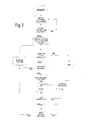
- Figure 3 illustrates the programming of the controller 9.
- heating is carried out rapidly with an optimum coil current, which may be a maximum current available.
- the temperature of the article is detected and compared with an offset temperature which is a predetermined amount below the desired temperature, for example 5 to 10°C below.
- the offset temperature is reached, the voltage gain on the inverter is reduced to a predetermined lower level and the temperature continues to be monitored. If the desired temperature, the set point, is not reached, the voltage gain is increased by a small increment and the temperature again measured. This is repeated until the set point is reached, as a result of which the voltage gain is reduced to a low level, below the predetermined lower level hereinbefore mentioned. After a delay, the effect on the temperature is again checked.
- the frequency of the supply to the coils is increased by a predetermined amount, and the temperature checked after the delay. This is repeated until the temperature begins to decrease. If the temperature drops below the set point, the voltage gain is then increased, and the effect monitored as described hereinbefore. If the temperature does not drop below the set point, the temperature continues to be monitored without the need for corrective action. In this way, the temperature of the article being heated can be controlled very precisely.
Landscapes
- Physics & Mathematics (AREA)
- Electromagnetism (AREA)
- General Induction Heating (AREA)
Claims (7)
- Magnetisches Heizsystem, welches einen Kern (4 - 6) aus einem magnetischen Material mit einer Spule (2,3) aufweist, die um zumindest einen Teil desselben gewickelt ist, und eine Stromversorgung (L 1-L 3), die mit der Spule zum Versorgen mit einem niederfrequenten Wechselstrom verbunden ist, wodurch ein Artikel (7) beheizt wird, und eine Sensoreinrichtung (8) zum Erfassen der Temperatur des Artikels, der beheizt wird, wobei die Stromversorgung Einrichtungen zum Variieren der Spannung und Frequenz des Wechselstroms in der Spule aufweist, und wobei die Spannungsversorgung derart angeordnet ist, um in Reaktion auf die erfaßte Temperatur, die durch die Sensoreinrichtung (8) erfaßt wird, geregelt (9) zu werden, dadurch gekennzeichnet, daß in einer ersten Phase der Spannungszuwachs der Stromversorgung automatisch geregelt wird, um die Temperatur des Artikels auf eine Offsettemperatur anzuheben und in einer zweiten Phase die Frequenz automatisch variiert wird, wodurch die Temperatur des Artikels von der Offsettemperatur zu einer vorbestimmten Temperatur angehoben wird, und um die Temperatur des Artikels bei dem vorbestimmten Wert zu halten.
- Magnetisches Heizsystem nach Patentanspruch 1, wobei die Einrichtung zum Variieren der Frequenz einen Inverter (1) aufweist.
- Magnetisches Heizsystem nach Patentanspruch 1 oder 2, wobei die Offsettemperatur geringer ist als die vorbestimmte Temperatur.
- Magnetisches Heizsystem nach Patentanspruch 3, wobei die Offsettemperatur 5 bis 10° Celsius geringer ist, als die vorbestimmte Temperatur.
- Magnetisches Heizsystem nach irgend einem der vorstehenden Patentansprüche, wobei die Stromversorgung eine drei Phasen Stromversorgung (L 1 - L 3) ist.
- Magnetisches Heizsystem nach Patentanspruch 5, wobei die Spule (2, 3) über zwei Phasen (U, V) verbunden ist.
- Magnetisches Heizsystem nach Patentanspruch 6, wobei zwei Spulen (2, 3) um den selben Kern (4 - 6) gewickelt sind, und wobei die Versorgung mit denen Spulen parallel verbunden ist.
Applications Claiming Priority (2)
| Application Number | Priority Date | Filing Date | Title |
|---|---|---|---|
| GBGB9826232.2A GB9826232D0 (en) | 1998-12-01 | 1998-12-01 | Magnetic heating system |
| GB9826232 | 1998-12-01 |
Publications (3)
| Publication Number | Publication Date |
|---|---|
| EP1006757A2 EP1006757A2 (de) | 2000-06-07 |
| EP1006757A3 EP1006757A3 (de) | 2001-11-21 |
| EP1006757B1 true EP1006757B1 (de) | 2004-02-04 |
Family
ID=10843329
Family Applications (1)
| Application Number | Title | Priority Date | Filing Date |
|---|---|---|---|
| EP99309647A Expired - Lifetime EP1006757B1 (de) | 1998-12-01 | 1999-12-01 | Magnetische Beheizungssystem |
Country Status (4)
| Country | Link |
|---|---|
| EP (1) | EP1006757B1 (de) |
| AT (1) | ATE259137T1 (de) |
| DE (1) | DE69914573T2 (de) |
| GB (1) | GB9826232D0 (de) |
Families Citing this family (2)
| Publication number | Priority date | Publication date | Assignee | Title |
|---|---|---|---|---|
| US6781100B2 (en) | 2001-06-26 | 2004-08-24 | Husky Injection Molding Systems, Ltd. | Method for inductive and resistive heating of an object |
| US6717118B2 (en) | 2001-06-26 | 2004-04-06 | Husky Injection Molding Systems, Ltd | Apparatus for inductive and resistive heating of an object |
Family Cites Families (4)
| Publication number | Priority date | Publication date | Assignee | Title |
|---|---|---|---|---|
| US3816690A (en) * | 1972-09-18 | 1974-06-11 | Illinois Tool Works | Induction heating apparatus |
| US5272720A (en) * | 1990-01-31 | 1993-12-21 | Inductotherm Corp. | Induction heating apparatus and method |
| JPH05299161A (ja) * | 1992-04-24 | 1993-11-12 | Fuji Electric Co Ltd | 誘導炉給電方法 |
| JP3398172B2 (ja) * | 1993-04-09 | 2003-04-21 | 電気興業株式会社 | 高周波誘導加熱における加熱温度制御方法及び高周波誘導加熱温度制御装置 |
-
1998
- 1998-12-01 GB GBGB9826232.2A patent/GB9826232D0/en not_active Ceased
-
1999
- 1999-12-01 DE DE69914573T patent/DE69914573T2/de not_active Expired - Lifetime
- 1999-12-01 EP EP99309647A patent/EP1006757B1/de not_active Expired - Lifetime
- 1999-12-01 AT AT99309647T patent/ATE259137T1/de not_active IP Right Cessation
Also Published As
| Publication number | Publication date |
|---|---|
| ATE259137T1 (de) | 2004-02-15 |
| DE69914573D1 (de) | 2004-03-11 |
| DE69914573T2 (de) | 2004-12-16 |
| EP1006757A2 (de) | 2000-06-07 |
| EP1006757A3 (de) | 2001-11-21 |
| GB9826232D0 (en) | 1999-01-20 |
Similar Documents
| Publication | Publication Date | Title |
|---|---|---|
| EP1718117B1 (de) | Induktionsheizvorrichtung und Verfahren zur Regelung der thermischen Verteilung | |
| KR101433054B1 (ko) | 워크피스의 유도 가열처리 | |
| JP5052329B2 (ja) | 電磁誘導加熱装置 | |
| CA1245727A (en) | Levitation heating using single variable frequency power supply | |
| GB2261125A (en) | Dc resistance welding apparatus | |
| US4327268A (en) | Current control system for an induction heating apparatus | |
| US6815649B2 (en) | Device and method for inductive billet heating with a billet-heating coil | |
| US5196668A (en) | DC resistance welding apparatus | |
| US20210099098A1 (en) | High frequency power supply system with closely regulated output for heating a workpiece | |
| EP1006757A2 (de) | Magnetische Beheizungssystem | |
| US8102682B2 (en) | Power supply control circuit for an inductive coil used to heat a tool shrink attachment | |
| KR100493337B1 (ko) | 고주파 펄스 발진기 | |
| AU685011B2 (en) | Method and apparatus for controlling heating and cooling in segments of a fiber glass bushing | |
| US4481639A (en) | Method for temperature control of inductors | |
| CN213073154U (zh) | 一种自动阻抗调节的感应加热、熔化的变频电源系统 | |
| JPS639352B2 (de) | ||
| JPH07249478A (ja) | ビレットヒータ装置 | |
| JP2736162B2 (ja) | モールドコイルの硬化方法及びその硬化装置 | |
| JP3398823B2 (ja) | ホットノズル用温度コントローラ | |
| JPH0622948Y2 (ja) | 高周波加熱装置 | |
| JPS6262426B2 (de) | ||
| JP5074535B2 (ja) | 誘導溶解炉の制御装置 | |
| JPH053074A (ja) | 誘導加熱用インバータ装置の制御方法 | |
| RU2112328C1 (ru) | Способ штучного нагрева заготовок из ферромагнитного материала токами высокой частоты | |
| WO2004083756A1 (en) | High frequency inductive melting furnace system for alarming poor feeding and excessive generation of air gap |
Legal Events
| Date | Code | Title | Description |
|---|---|---|---|
| PUAI | Public reference made under article 153(3) epc to a published international application that has entered the european phase |
Free format text: ORIGINAL CODE: 0009012 |
|
| AK | Designated contracting states |
Kind code of ref document: A2 Designated state(s): AT BE CH CY DE DK ES FI FR GB GR IE IT LI LU MC NL PT SE |
|
| AX | Request for extension of the european patent |
Free format text: AL;LT;LV;MK;RO;SI |
|
| PUAL | Search report despatched |
Free format text: ORIGINAL CODE: 0009013 |
|
| AK | Designated contracting states |
Kind code of ref document: A3 Designated state(s): AT BE CH CY DE DK ES FI FR GB GR IE IT LI LU MC NL PT SE |
|
| AX | Request for extension of the european patent |
Free format text: AL;LT;LV;MK;RO;SI |
|
| AKX | Designation fees paid | ||
| REG | Reference to a national code |
Ref country code: DE Ref legal event code: 8566 |
|
| 17P | Request for examination filed |
Effective date: 20020722 |
|
| RBV | Designated contracting states (corrected) |
Designated state(s): AT BE CH CY DE DK ES FI FR GB GR IE IT LI LU MC NL PT SE |
|
| 17Q | First examination report despatched |
Effective date: 20021003 |
|
| GRAP | Despatch of communication of intention to grant a patent |
Free format text: ORIGINAL CODE: EPIDOSNIGR1 |
|
| GRAS | Grant fee paid |
Free format text: ORIGINAL CODE: EPIDOSNIGR3 |
|
| GRAA | (expected) grant |
Free format text: ORIGINAL CODE: 0009210 |
|
| AK | Designated contracting states |
Kind code of ref document: B1 Designated state(s): AT BE CH CY DE DK ES FI FR GB GR IE IT LI LU MC NL PT SE |
|
| PG25 | Lapsed in a contracting state [announced via postgrant information from national office to epo] |
Ref country code: NL Free format text: LAPSE BECAUSE OF FAILURE TO SUBMIT A TRANSLATION OF THE DESCRIPTION OR TO PAY THE FEE WITHIN THE PRESCRIBED TIME-LIMIT Effective date: 20040204 Ref country code: LI Free format text: LAPSE BECAUSE OF FAILURE TO SUBMIT A TRANSLATION OF THE DESCRIPTION OR TO PAY THE FEE WITHIN THE PRESCRIBED TIME-LIMIT Effective date: 20040204 Ref country code: IT Free format text: LAPSE BECAUSE OF FAILURE TO SUBMIT A TRANSLATION OF THE DESCRIPTION OR TO PAY THE FEE WITHIN THE PRESCRIBED TIME-LIMIT;WARNING: LAPSES OF ITALIAN PATENTS WITH EFFECTIVE DATE BEFORE 2007 MAY HAVE OCCURRED AT ANY TIME BEFORE 2007. THE CORRECT EFFECTIVE DATE MAY BE DIFFERENT FROM THE ONE RECORDED. Effective date: 20040204 Ref country code: FR Free format text: LAPSE BECAUSE OF FAILURE TO SUBMIT A TRANSLATION OF THE DESCRIPTION OR TO PAY THE FEE WITHIN THE PRESCRIBED TIME-LIMIT Effective date: 20040204 Ref country code: FI Free format text: LAPSE BECAUSE OF FAILURE TO SUBMIT A TRANSLATION OF THE DESCRIPTION OR TO PAY THE FEE WITHIN THE PRESCRIBED TIME-LIMIT Effective date: 20040204 Ref country code: CY Free format text: LAPSE BECAUSE OF FAILURE TO SUBMIT A TRANSLATION OF THE DESCRIPTION OR TO PAY THE FEE WITHIN THE PRESCRIBED TIME-LIMIT Effective date: 20040204 Ref country code: CH Free format text: LAPSE BECAUSE OF FAILURE TO SUBMIT A TRANSLATION OF THE DESCRIPTION OR TO PAY THE FEE WITHIN THE PRESCRIBED TIME-LIMIT Effective date: 20040204 Ref country code: BE Free format text: LAPSE BECAUSE OF FAILURE TO SUBMIT A TRANSLATION OF THE DESCRIPTION OR TO PAY THE FEE WITHIN THE PRESCRIBED TIME-LIMIT Effective date: 20040204 Ref country code: AT Free format text: LAPSE BECAUSE OF FAILURE TO SUBMIT A TRANSLATION OF THE DESCRIPTION OR TO PAY THE FEE WITHIN THE PRESCRIBED TIME-LIMIT Effective date: 20040204 |
|
| REG | Reference to a national code |
Ref country code: GB Ref legal event code: FG4D |
|
| REG | Reference to a national code |
Ref country code: CH Ref legal event code: EP |
|
| REG | Reference to a national code |
Ref country code: IE Ref legal event code: FG4D |
|
| REF | Corresponds to: |
Ref document number: 69914573 Country of ref document: DE Date of ref document: 20040311 Kind code of ref document: P |
|
| PG25 | Lapsed in a contracting state [announced via postgrant information from national office to epo] |
Ref country code: GR Free format text: LAPSE BECAUSE OF FAILURE TO SUBMIT A TRANSLATION OF THE DESCRIPTION OR TO PAY THE FEE WITHIN THE PRESCRIBED TIME-LIMIT Effective date: 20040504 Ref country code: DK Free format text: LAPSE BECAUSE OF FAILURE TO SUBMIT A TRANSLATION OF THE DESCRIPTION OR TO PAY THE FEE WITHIN THE PRESCRIBED TIME-LIMIT Effective date: 20040504 |
|
| PG25 | Lapsed in a contracting state [announced via postgrant information from national office to epo] |
Ref country code: ES Free format text: LAPSE BECAUSE OF FAILURE TO SUBMIT A TRANSLATION OF THE DESCRIPTION OR TO PAY THE FEE WITHIN THE PRESCRIBED TIME-LIMIT Effective date: 20040515 |
|
| NLV1 | Nl: lapsed or annulled due to failure to fulfill the requirements of art. 29p and 29m of the patents act | ||
| REG | Reference to a national code |
Ref country code: CH Ref legal event code: PL |
|
| PG25 | Lapsed in a contracting state [announced via postgrant information from national office to epo] |
Ref country code: LU Free format text: LAPSE BECAUSE OF NON-PAYMENT OF DUE FEES Effective date: 20041201 Ref country code: IE Free format text: LAPSE BECAUSE OF NON-PAYMENT OF DUE FEES Effective date: 20041201 Ref country code: GB Free format text: LAPSE BECAUSE OF NON-PAYMENT OF DUE FEES Effective date: 20041201 |
|
| PLBE | No opposition filed within time limit |
Free format text: ORIGINAL CODE: 0009261 |
|
| PG25 | Lapsed in a contracting state [announced via postgrant information from national office to epo] |
Ref country code: MC Free format text: LAPSE BECAUSE OF NON-PAYMENT OF DUE FEES Effective date: 20041231 |
|
| 26N | No opposition filed |
Effective date: 20041105 |
|
| EN | Fr: translation not filed | ||
| GBPC | Gb: european patent ceased through non-payment of renewal fee |
Effective date: 20041201 |
|
| REG | Reference to a national code |
Ref country code: IE Ref legal event code: MM4A |
|
| PG25 | Lapsed in a contracting state [announced via postgrant information from national office to epo] |
Ref country code: PT Free format text: LAPSE BECAUSE OF NON-PAYMENT OF DUE FEES Effective date: 20040704 |
|
| PGFP | Annual fee paid to national office [announced via postgrant information from national office to epo] |
Ref country code: SE Payment date: 20091218 Year of fee payment: 11 |
|
| PGFP | Annual fee paid to national office [announced via postgrant information from national office to epo] |
Ref country code: DE Payment date: 20091231 Year of fee payment: 11 |
|
| REG | Reference to a national code |
Ref country code: SE Ref legal event code: EUG |
|
| PG25 | Lapsed in a contracting state [announced via postgrant information from national office to epo] |
Ref country code: SE Free format text: LAPSE BECAUSE OF NON-PAYMENT OF DUE FEES Effective date: 20101202 |
|
| REG | Reference to a national code |
Ref country code: DE Ref legal event code: R119 Ref document number: 69914573 Country of ref document: DE Effective date: 20110701 |
|
| PG25 | Lapsed in a contracting state [announced via postgrant information from national office to epo] |
Ref country code: DE Free format text: LAPSE BECAUSE OF NON-PAYMENT OF DUE FEES Effective date: 20110701 |