EP1006835B1 - Hakenförmige vorrichtung - Google Patents
Hakenförmige vorrichtung Download PDFInfo
- Publication number
- EP1006835B1 EP1006835B1 EP98921965A EP98921965A EP1006835B1 EP 1006835 B1 EP1006835 B1 EP 1006835B1 EP 98921965 A EP98921965 A EP 98921965A EP 98921965 A EP98921965 A EP 98921965A EP 1006835 B1 EP1006835 B1 EP 1006835B1
- Authority
- EP
- European Patent Office
- Prior art keywords
- main part
- tongue
- hook
- arrangement according
- plane
- Prior art date
- Legal status (The legal status is an assumption and is not a legal conclusion. Google has not performed a legal analysis and makes no representation as to the accuracy of the status listed.)
- Expired - Lifetime
Links
- 239000000463 material Substances 0.000 claims description 11
- 241000270722 Crocodylidae Species 0.000 claims description 9
- LNNWVNGFPYWNQE-GMIGKAJZSA-N desomorphine Chemical compound C1C2=CC=C(O)C3=C2[C@]24CCN(C)[C@H]1[C@@H]2CCC[C@@H]4O3 LNNWVNGFPYWNQE-GMIGKAJZSA-N 0.000 claims description 9
- 239000004033 plastic Substances 0.000 claims description 8
- 239000004417 polycarbonate Substances 0.000 claims description 5
- 229920000515 polycarbonate Polymers 0.000 claims description 5
- 239000011159 matrix material Substances 0.000 description 4
- 238000000034 method Methods 0.000 description 4
- 230000008569 process Effects 0.000 description 4
- 238000001816 cooling Methods 0.000 description 2
- 238000004519 manufacturing process Methods 0.000 description 2
- 210000000481 breast Anatomy 0.000 description 1
- 230000008859 change Effects 0.000 description 1
- 239000007795 chemical reaction product Substances 0.000 description 1
- 238000010276 construction Methods 0.000 description 1
- 238000001125 extrusion Methods 0.000 description 1
- 238000012986 modification Methods 0.000 description 1
- 230000004048 modification Effects 0.000 description 1
- 238000000465 moulding Methods 0.000 description 1
- 238000010422 painting Methods 0.000 description 1
Images

Classifications
-
- A—HUMAN NECESSITIES
- A45—HAND OR TRAVELLING ARTICLES
- A45F—TRAVELLING OR CAMP EQUIPMENT: SACKS OR PACKS CARRIED ON THE BODY
- A45F5/00—Holders or carriers for hand articles; Holders or carriers for use while travelling or camping
- A45F5/02—Fastening articles to the garment
-
- A—HUMAN NECESSITIES
- A44—HABERDASHERY; JEWELLERY
- A44C—PERSONAL ADORNMENTS, e.g. JEWELLERY; COINS
- A44C3/00—Medals; Badges
- A44C3/001—Badges
-
- G—PHYSICS
- G09—EDUCATION; CRYPTOGRAPHY; DISPLAY; ADVERTISING; SEALS
- G09F—DISPLAYING; ADVERTISING; SIGNS; LABELS OR NAME-PLATES; SEALS
- G09F3/00—Labels, tag tickets, or similar identification or indication means; Seals; Postage or like stamps
- G09F3/08—Fastening or securing by means not forming part of the material of the label itself
- G09F3/14—Fastening or securing by means not forming part of the material of the label itself by strings, straps, chains, or wires
-
- Y—GENERAL TAGGING OF NEW TECHNOLOGICAL DEVELOPMENTS; GENERAL TAGGING OF CROSS-SECTIONAL TECHNOLOGIES SPANNING OVER SEVERAL SECTIONS OF THE IPC; TECHNICAL SUBJECTS COVERED BY FORMER USPC CROSS-REFERENCE ART COLLECTIONS [XRACs] AND DIGESTS
- Y10—TECHNICAL SUBJECTS COVERED BY FORMER USPC
- Y10T—TECHNICAL SUBJECTS COVERED BY FORMER US CLASSIFICATION
- Y10T24/00—Buckles, buttons, clasps, etc.
- Y10T24/13—Article holder attachable to apparel or body
- Y10T24/1379—Key ring holder
-
- Y—GENERAL TAGGING OF NEW TECHNOLOGICAL DEVELOPMENTS; GENERAL TAGGING OF CROSS-SECTIONAL TECHNOLOGIES SPANNING OVER SEVERAL SECTIONS OF THE IPC; TECHNICAL SUBJECTS COVERED BY FORMER USPC CROSS-REFERENCE ART COLLECTIONS [XRACs] AND DIGESTS
- Y10—TECHNICAL SUBJECTS COVERED BY FORMER USPC
- Y10T—TECHNICAL SUBJECTS COVERED BY FORMER US CLASSIFICATION
- Y10T24/00—Buckles, buttons, clasps, etc.
- Y10T24/13—Article holder attachable to apparel or body
- Y10T24/1391—Article held by clip with spring [e.g., leaf, coil] member
-
- Y—GENERAL TAGGING OF NEW TECHNOLOGICAL DEVELOPMENTS; GENERAL TAGGING OF CROSS-SECTIONAL TECHNOLOGIES SPANNING OVER SEVERAL SECTIONS OF THE IPC; TECHNICAL SUBJECTS COVERED BY FORMER USPC CROSS-REFERENCE ART COLLECTIONS [XRACs] AND DIGESTS
- Y10—TECHNICAL SUBJECTS COVERED BY FORMER USPC
- Y10T—TECHNICAL SUBJECTS COVERED BY FORMER US CLASSIFICATION
- Y10T24/00—Buckles, buttons, clasps, etc.
- Y10T24/13—Article holder attachable to apparel or body
- Y10T24/1394—Article held by clip
Definitions
- the present invention relates to a hook-shaped arrangement and more particularly to a hook-shaped arrangement that comprises a main part, a hook-shaped device integral with said main part, and a holding device which is either integral with or attached to said main part.
- the hook-shaped device is formed at one end of the main part and is adapted so that although it can be easily affixed to an object, it can only be removed from said object with difficulty, whereas the holding device is either formed integrally with or is attachable to the other end of the main part of said device and is adapted to be readily applied to a holding means so as to be readily fastened to and readily removed therefrom.
- the present invention is primarily intended for use with an object, such as an identity card, and the holding means may comprise a chosen part of a person's clothing, such as the edge of a breast pocket.
- the hook-shaped arrangement is comprised of a part which is partly circular in cross-section and which includes an angle of arc of slightly less than 360°.
- This Design Application also discloses that the centre of said curved part is positioned in, or at least substantially in, a plane that extends through a central plane of the main part.
- the device also includes a suitable slot between the free end of the curved part and said main part, while the free end of the curved part is angled away from said main part.
- the main part has the same thickness as the curved part.
- Another technical problem is one of enabling said hook-shaped arrangement to be produced from a suitable and durable plastic material, and to adapt said hook-shaped device so that it can be caused to co-act readily with an identity card or like object with the main part of the hook-shaped device and said identity card being in specific alignment with one another.
- Another technical problem is one of providing such a device that will ensure that the main part and the identity card will be positioned closely adjacent one another.
- a further technical problem is one of designing the hook-shaped device such that when a slotted identity card is caused to co-act with the hook-shaped device, it will only be possible to remove the identity card from said device after having turned the identity card about a horizontal rotational axis through an angle of 180° from its normal suspended position and into abutment with said main part, without needing to manipulate the hook-shaped device.
- Another technical problem is one of realising the significance of and the advantages associated with allowing the free end of said tongue to extend in, or essentially in, a plane that coincides with a plane on that side surface of said main part which lies opposite to said one side surface of said main part.
- Another technical problem is one of realising the significance of giving the tongue a thickness that is half the thickness, or essentially half the thickness, of the main part.
- a technical problem is one of realising the significance of and the advantages afforded by providing or forming on one end of the main part a projection that faces towards said tongue and that is positioned close to the side surface of said main part that lies opposite said one side surface of said main part and that is positioned in the region between said opposing side surfaces.
- Another technical problem is one of realising the significance of positioning the centre of said curved tongue on one side of a plane on one of the side surfaces of said main part and extending from said plane on that side surface of the main part which lies opposite to said one side surface of said main part.
- Another technical problem is one of realising the significance of providing said main part in the proximity of said other end with one or two circular, barbed projections that will enable the hook-shaped device to be secured firmly to a holding means and rotated relative thereto when necessary.
- a technical problem resides in realising the significance of providing said projection on one side surface of said main part and adapting said projection for a first type of holding means, such as a suspenders clip.
- Another technical problem is one of realising the significance of providing a second type of projection on that side surface of the main part which lies opposite said one side surface of said main part and which is adapted for co-action with another type of holding means, such as a crocodile clip.
- Another technical problem is one of realising the significance of and the advantages associated with producing said main part and said hook-shaped, tongue-like device from a plastic material, such as polycarbonate, such that said main part and said hook-shaped device can be produced in a two-part matrix, by means of an extrusion process or like process.
- Another technical problem is one of realising the significance of and the advantages that are afforded by allowing the free end of the tongue to present a bevelled or rounded surface to one of the side surfaces of said main part.
- the present invention is based on a hook-shaped arrangement of the kind described in the introduction.
- a hook-shaped device shall comprise a tongue which is partly circular in cross-section, or at least essentially partly circular, having an angle of arc that is slightly less than 360°, and that the centre of the curved tongue is located in, or essentially in, a plane that is orientated to coincide with a plane on one side surface of said main part, and that the free end of the tongue extends in, or at least essentially in, a plane that is orientated to coincide with a plane on that side surface of the main part which lies opposite to said one side surface of said main part and in flot the tongue overlaps the main part.
- the angle of arc of the circular tongue is greater than 360° and less than 340°.
- the tongue will have a thickness which is half the thickness, or at least essentially half the thickness, of the main part.
- the tongue will have a width which is equal to or at least essentially equal to the width of the main part, and that the width chosen will be slightly smaller than the length of a slot provided in an identity card in the proximity of an outer edge-part of said card.
- one end of the main part of said device will include a projection that faces towards said tongue and that is located adjacent that side surface of said main part which lies opposite to said one side surface of the main part and located between said opposing side surfaces.
- centre of said curved tongue will be located on one side of a plane on one side surface of the main part of the device and in a direction from said plane located on the side surface of said main part that lies opposite said one of said main-part side surfaces.
- the angle of arc contained by said circular, curved tongue section is greater than 320° and smaller than 350°.
- the second end of the main part shall include one or more circular, barbed projections which will enable the hook-shaped device to be secured firmly to a holding means and rotated in relation thereto when necessary.
- one side surface of the main part includes a first type of projection by means of which the hook-shaped device can be firmly secured to a first type of holding means, such as a suspender clip.
- That side surface of the main part opposite to said one side surface of said main part will conveniently include a second type of projection which enables the hook-shaped device to be secured firmly to a second type of holding means, such as a crocodile clip.
- the diameter of the curved tongue and the thickness of the tongue will conveniently be less than the distance from one outer edge of the identity card to a slotted card-delimiting edge facing towards said outer edge.
- the main part and the hook-shaped device belonging to said hook-shaped device may conveniently be made of a plastic material, and then particularly a polycarbonate material.
- the free end of the tongue will preferably have a bevelled or rounded surface that faces towards said one side surface of said main part.
- an inventive hook-shaped arrangement Those advantages primarily afforded by an inventive hook-shaped arrangement are found in the provision of conditions whereby the main part and a hook-shaped device formed integrally therewith can be produced in a simple manner and so that said device can be readily attached to an object with the hook-shaped device and said object in chosen relative positions, wherewith, when applied, the hook-shaped device will hold the object securely, i.e. an identity card and can only be removed from said holding means with difficulty.
- One edge of the identity card can be easily inserted into the hook-shaped device, by allowing the slot in said card to pass around the part-circular tongue. With the card secured in this way, the card can only be removed by rotating the card to a position parallel with and close to said one side surface of the main part.
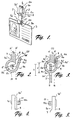
- Fig. 1 is a perspective view of a hook-shaped arrangement 1 which includes a main part 1a, a hook-shaped device 1b integral with said main part and a holding means 2 attached to the main part.
- the hook-shaped device 1b is formed at one end 1a' of the main part 1a and is adapted to firmly hold an object, such as the identity card 3 shown in Fig. 1, while being not readily removable from said object.
- the holding means 2 can be attached to the other end 1a'' of the main part 1a and functions to secure the device to a holding means 4, such as part of a wearer's clothing.
- This holding means 4 is only indicated in Fig. 1.
- Fig. 2 is a side view which shows one end 1a' of the main part 1a and the shape of the hook-shaped device 1b immediately after its manufacture.
- the hook-shaped device 1b and the main part 1a are moulded from a plastic material in a two-part matrix.
- the hook-shaped device 1b includes a tongue 5 whose free end 5a is divergent in relation to the main part 1a, said tongue 5 being brought to the state shown in Fig. 3 by subsequent cooling of said tongue.
- Fig. 2 is intended to show that cooling of a plastic component will result in a shape change that can be utilised in accordance with the present invention.
- the end product shown in Fig. 3, shall present a very small gap 5a' between the free end 5a and a region 8a of the main part of said device, this region being flat in the illustrated case.
- twist-shaped device 1b has a thickness which is smaller than the thickness of the main part 1a.
- the hook-shaped device 1b is comprised of a circular-arcuate part 5c that has an inner surface 5b which includes an angle of arc "a" and a straight, free end 5a.
- the length of the free end 5a corresponds to, or at least essentially to, the diameter of the arcuate part 5c.
- the end 5a will preferably be slightly longer than said diameter.
- Fig. 3 shows the main part 1a and the hook-shaped device 1b in a final state in which a slot 6 or like aperture is formed at the terminating part of the free end 5a.
- the tip of the free end 5a is rounded or bevelled at 5d so as to define the slot 6.
- the edge 3a of said card When attaching an identity card to the hook-shaped device 1b, the edge 3a of said card is caused to connect with the slot 6, so that the card 3 takes a position immediately adjacent to or against the surface 8 of the main part 1a, therewith enabling the edge 3a to be inserted into the interior of the hook-shaped device 1b and the rounded or bevelled tip 5d to pass through a slot 5a', so that the hook-shaped device 1b and the identity card 3 are able to take the position shown in Fig. 3, this position corresponding to that shown in Fig. 1.
- the hook-shaped device 1b has the form of a tongue 5 which is partly circular, or at least essentially part-circular, in cross-section.
- partially circular shall be understood as meaning a circular section 5c that does not form a closed circle but that has an angle of arc which is smaller than 360° and/or that the section 5c has a cross-sectional shape that deviates slightly from a circular shape.
- the circular part 5c of the tongue 5 shall then have an angle of arc (a) that is only slightly smaller than 360° in practice.
- a centre 5' on the circular part 5c lies in, or at least essentially in, a plane "A” that is able to coincide with a plane “A'” that lies on and coincides with one of the side surfaces 7 of the main part 1a, and the free end 5a of the tongue 5 extends in, or at least essentially in, a plane “B” that is able to coincide with a plane “B'” which lies in and coincides with the side surface 8 of the main part 1a that lies opposite said one surface 7 of the two opposing side surfaces 7, 8 of the main part.
- This definition may, more specifically, be taken to mean a surface 5a'' of the free end 5a that defines the gap 5a'.
- the angle of arc of the circular arc 5c is greater than 300° and smaller than 340°, with the inner circular surface 5b of the hook-shaped device 1b being able to touch the plane "B", i.e. to be tangential to said plane.
- the tongue 5 has a thickness which is half the thickness, or at least essentially half the thickness, of the main part 1a.
- the width of the tongue 5 is equal to, or at least essentially equal to, the width of the main part 1a.
- the end region 1a' of the main part 1a is provided with or shaped as a projection 9 which faces towards the tongue 5 and orientated close to the side surface 8 of said main part 1a, this surface being opposite to said one side surface 7 of said main part and orientated between said mutually opposing side surface 7, 8.
- the cross-sectional shape of the projection 9 is obtained by allowing the circular surface 5b of the tongue 5 to pass beyond the main part 1a such as to form a projection whose tip 9a is located within the region located between the surfaces 5b and 5a''.
- the main part 1a is formed with one or two circular projections 10, 11 at its other end 1a''.
- the circular projection is/are provided with four uniformly distributed barbs 10a, 11a and can be affixed to a holding means 2 of known construction and rotated relative thereto when necessary.
- Fig. 4 shows a first type of projection 10 on one side surface 8 of the main part 1a, this projection being adapted for co-action with a first type of holding means 2, such as a braces clip shown more clearly in Fig. 7.
- Fig. 5 shows a second type of projection 11 provided on the side surface 7 of the main part 1a opposite to said side surface 8, this projection being adapted for co-action with a second type of holding means 2, such as a crocodile clip, shown more clearly in Fig. 1.
- a second type of holding means 2 such as a crocodile clip
- the inner diameter of the curved tongue (i.e. the circular surface 5b) and the thickness (b') of the tongue 5 are slightly smaller than the distance "b" from one outer edge 3a of the card 2 to a slot defining edge 3b' of said card facing towards said outer edge 3a.
- the main part 1a and the hook-shaped device 1b of said device are made of a plastic material, preferably a polycarbonate material.
- the free end of the tongue is bevelled or rounded 5d towards the side surface 8 of the main part, so as to define said slot 6.
- Fig. 6 illustrates an alternative embodiment where the centre 5' of the curved tongue 5 is located on one side of a plane "A" that coincides with a plane "A'", e.g. the side surface 7 of the main part 1a, and, in a direction away from the plane "B", is orientated to coincide with a plane, e.g. the side surface 8 of the main part.
- This lateral offset between the centres 5' shown in Figs. 2 and 6 shall normally be smaller than 25% of the diameter of the surface 5b.
- the angle of arc of the curved tongue 5 and its circular surface 5b is greater than 320° and smaller than 350°.
- the holding means 2 has the form of a known crocodile clip that includes spring-loaded jaws 2a, 2b and an intermediate rotary axle 2c.
- the jaw 2b is attached to the other end 1a'' of the main part 1a in a known manner.
- Fig. 7 illustrates the use of a braces or suspender clip 2' with the jaws 2a' and 2b' being shown in an open position.
- An intermediate rotary shaft 2c' is also used in this case.
- the jaw 2a' can be moved to a closed position, by means of a wing-shaped means 2d.
- Fig. 8 illustrates an alternative embodiment of a crocodile clip having jaws 2a, 2b, of which the jaw 2b is attached to the other end 1a'' of the main part 1a in a known manner.
Landscapes
- Physics & Mathematics (AREA)
- General Physics & Mathematics (AREA)
- Engineering & Computer Science (AREA)
- Theoretical Computer Science (AREA)
- Hooks, Suction Cups, And Attachment By Adhesive Means (AREA)
- Supports Or Holders For Household Use (AREA)
- Advancing Webs (AREA)
- Load-Engaging Elements For Cranes (AREA)
- Chain Conveyers (AREA)
- Absorbent Articles And Supports Therefor (AREA)
- Materials For Medical Uses (AREA)
- Prostheses (AREA)
- Slide Fasteners, Snap Fasteners, And Hook Fasteners (AREA)
- Clamps And Clips (AREA)
Claims (13)
- Hakenförmige Vorrichtung bzw. Anordnung (1), welche ein Hauptteil (1a), eine hakenförmige Vorrichtung (1b) integral mit dem Hauptteil und ein Haltemittel (2) umfaßt, welches mit dem Hauptteil integral ist oder an diesem festgelegt ist, wobei die hakenförmige Vorrichtung (1b) an einem Ende des Hauptteils (1a) angeordnet ist und adaptiert ist, um fest einen Gegenstand, wie eine Identitätskarte (3) zu halten, während sie nicht leicht davon entfernbar ist, und wobei das Haltemittel (2) als das andere Ende des Hauptteils (1a) ausgebildet ist oder an diesem festlegbar ist und fähig ist, an ein Haltemittel festgelegt zu werden und leicht von diesem, beispielsweise einem Teil einer Bekleidung des Trägers, entfernt zu werden, die hakenförmige Vorrichtung (1a) eine Zunge (5) umfaßt, welche eine teilweise kreisförmige oder zumindest im wesentlichen teilweise kreisförmige Querschnittsform aufweist, die einen Bogenwinkel geringfügig kleiner als 360° aufweist; das Zentrum der gekrümmten Zunge (5) in oder wenigstens im wesentlichen in einer Ebene (A) angeordnet ist, welche orientiert ist, um mit einer Ebene auf einer Seitenoberfläche (7) des Hauptteils (1a) zusammenzufallen, dadurch gekennzeichnet, daß sich das freie Ende (5a) der Zunge (5) in oder wenigstens im wesentlichen in einer Ebene (B) erstreckt, welche so orientiert ist, daß sie parallel mit einer Ebene ist, die an der Seitenoberfläche (8) des Hauptteils (1a) orientiert bzw. ausgerichtet ist, welche entgegengesetzt zu der einen Seitenoberfläche (7) des Hauptteils (1b) liegt, und daß die Zunge (5) das Hauptteil (1a) überlappt.
- Anordnung nach Anspruch 1, dadurch gekennzeichnet, daß der Bogenwinkel der kreisförmigen Querschnittsoberfläche der Zunge (5) größer als 300° und kleiner als 340° ist.
- Anordnung nach Anspruch 2, dadurch gekennzeichnet, daß die Dicke der Zunge (5) die Hälfte oder wenigstens im wesentlichen die Hälfte der Dicke des Hauptteils (1a) der Vorrichtung ist.
- Anordnung nach Anspruch 3, dadurch gekennzeichnet, daß die Breite der Zunge (5) gleich oder wenigstens im wesentlichen gleich der Breite des Hauptteils (1a) ist.
- Anordnung nach Anspruch 1, dadurch gekennzeichnet, daß das Hauptteil (1a) einen Vorsprung (9) umfaßt, welcher zu der Zunge (5) schaut und welcher in naher Nachbarschaft zu der Oberfläche (8) des Hauptteils (1a) angeordnet ist, welcher entgegengesetzt zu der einen Seitenoberfläche (7) des Hauptteils (1b) ist und zwischen den einander gegenüberliegenden Seitenoberflächen orientiert ist.
- Anordnung nach Anspruch 1, dadurch gekennzeichnet, daß das Hauptteil (1a) in der Nachbarschaft des anderen Endes ein oder zwei kreisförmige, mit Widerhaken versehene Vorsprünge (10, 11) aufweist, die adaptiert sind für eine feste Festlegung an Haltemitteln und fähig sind, in bezug zu den Mitteln, falls notwendig, rotiert zu werden.
- Anordnung nach Anspruch 6, gekennzeichnet durch ein erste Art eines Vorsprungs (10), welcher auf einer Seitenoberfläche (7, 8) des Hauptteils (1a) angeordnet ist und für ein Zusammenwirken mit einer ersten Art von Haltemitteln (2), wie Klammern oder Bandhängeclips, adaptiert ist.
- Anordnung nach Anspruch 6, gekennzeichnet durch eine zweite Art eines Vorsprung(s) (11), die an der Seitenoberfläche (8) des Hauptteils (1a) ausgebildet ist, welche gegenüberliegend der einen Seitenoberfläche (7) des Hauptteils (1a) angeordnet ist, wobei der Vorsprung (11) für ein Zusammenwirken mit einer zweiten Art von Haltemittel (2), wie einer Krokodilklemme, adaptiert ist.
- Anordnung nach Anspruch 1, dadurch gekennzeichnet, daß der Durchmesser der gekrümmten Zunge (5) und die Dicke der Zunge (5) geringfügig kleiner als der Abstand von einer Außenkante (3a) einer Identitätskarte (2) zu einer einen Schlitz definierenden Kante dieser Karte ist, welcher zu der Außenkante schaut.
- Anordnung nach Anspruch 1, dadurch gekennzeichnet, daß das Hauptteil (1a) und die hakenförmige Vorrichtung (1b) aus einem Kunststoffmaterial, vorzugsweise einen Polycarbonatmaterial, besteht.
- Anordnung nach Anspruch 1, dadurch gekennzeichnet, daß das freie Ende (5a) der Zunge (5) zu einer Seitenoberfläche des Hauptteils (1a) abgefast oder abgerundet ist.
- Anordnung nach Anspruch 1, dadurch gekennzeichnet, daß das Zentrum der gekrümmten Zunge (5) an einer Seite einer Ebene angeordnet ist, die auf einer Seitenoberfläche (7) des Hauptteils (1a) ausgerichtet bzw. orientiert ist und in einer Richtung weg von der Ebene auf jener Seitenoberfläche (8) des Hauptteils orientiert ist, welche der einen Seitenoberfläche (7) des Hauptteils gegenüberliegt.
- Anordnung nach Anspruch 12, dadurch gekennzeichnet, daß der Bogenwinkel der gekrümmten Zunge (5) größer als 320° und kleiner als 350° ist.
Applications Claiming Priority (3)
| Application Number | Priority Date | Filing Date | Title |
|---|---|---|---|
| SE9701743 | 1997-05-09 | ||
| SE9701743A SE514941C2 (sv) | 1997-05-09 | 1997-05-09 | Krokformat arrangemang för fasthållande av ett objekt såsom ett identiteskort |
| PCT/SE1998/000814 WO1998051187A1 (en) | 1997-05-09 | 1998-05-04 | Hook-shaped arrangement |
Publications (2)
| Publication Number | Publication Date |
|---|---|
| EP1006835A1 EP1006835A1 (de) | 2000-06-14 |
| EP1006835B1 true EP1006835B1 (de) | 2004-12-22 |
Family
ID=20406886
Family Applications (1)
| Application Number | Title | Priority Date | Filing Date |
|---|---|---|---|
| EP98921965A Expired - Lifetime EP1006835B1 (de) | 1997-05-09 | 1998-05-04 | Hakenförmige vorrichtung |
Country Status (7)
| Country | Link |
|---|---|
| US (1) | US6301751B1 (de) |
| EP (1) | EP1006835B1 (de) |
| AT (1) | ATE285187T1 (de) |
| AU (1) | AU7460998A (de) |
| DE (1) | DE69828292T2 (de) |
| SE (1) | SE514941C2 (de) |
| WO (1) | WO1998051187A1 (de) |
Families Citing this family (17)
| Publication number | Priority date | Publication date | Assignee | Title |
|---|---|---|---|---|
| US6594865B2 (en) * | 2001-01-11 | 2003-07-22 | O'mahony Sean Patrick | Retaining clip |
| US6598273B2 (en) * | 2001-09-10 | 2003-07-29 | J.A.M. Plastics, Inc. | Lanyard buckle connector |
| US20040045133A1 (en) * | 2002-09-06 | 2004-03-11 | Buettell Bruce J. | Double clamp card attachment |
| US7174607B1 (en) | 2002-09-30 | 2007-02-13 | J.A.M. Plastics, Inc. | Card attachment |
| US8230823B2 (en) * | 2003-12-31 | 2012-07-31 | Simoni Jacquelyn R | Dog flashlight kit |
| US20080127460A1 (en) * | 2006-12-05 | 2008-06-05 | Boris And Natasha, Inc. Dba Dynamic Business Associates | Eyeglass retainer |
| US20080224007A1 (en) * | 2007-03-12 | 2008-09-18 | Mo Ka-Wing | Quick release vent mounting clip |
| US7607627B1 (en) * | 2008-03-12 | 2009-10-27 | Hamid Mchatet | Clip holder for eyeglasses |
| US7546753B1 (en) * | 2008-05-07 | 2009-06-16 | Charm Zone, Inc. | Key chain attachment and location apparatus and method |
| USD633250S1 (en) * | 2009-08-03 | 2011-02-22 | Yu-Che Kao | Clamp for a light |
| US8146209B2 (en) * | 2009-08-13 | 2012-04-03 | Oliver C Carnate | Glove holder |
| USD708673S1 (en) * | 2011-11-14 | 2014-07-08 | Hai Pin Tsai | Name badge with a retractable cord |
| USD695838S1 (en) | 2012-03-23 | 2013-12-17 | Duane Cole | Identification tag |
| USD742354S1 (en) * | 2014-02-05 | 2015-11-03 | Sol Republic Inc. | Head phone strain relief attachment clip |
| USD776943S1 (en) * | 2015-04-15 | 2017-01-24 | Tracey Renee Busch Gunderson | Keepsake display |
| US10029085B1 (en) * | 2015-09-04 | 2018-07-24 | Neotech Products Llc | Tubing adjustable retention to bed clothing |
| USD804810S1 (en) * | 2016-03-02 | 2017-12-12 | David Brian Schmiedeberg | Bolo tie ID badge holder |
Family Cites Families (9)
| Publication number | Priority date | Publication date | Assignee | Title |
|---|---|---|---|---|
| US1353605A (en) * | 1920-09-21 | Check-holding device | ||
| US1207154A (en) * | 1916-01-17 | 1916-12-05 | Rosalie A W Fox | Supporting apparatus. |
| US2775804A (en) * | 1953-08-07 | 1957-01-01 | Sam F Ayoub | Key ring holder |
| US4277863A (en) * | 1979-05-11 | 1981-07-14 | Daniel Faneuf | Identification card holder |
| GB2103270B (en) * | 1981-07-23 | 1985-07-10 | Wall Ltd Howard | Securing device |
| US4974764A (en) * | 1989-05-11 | 1990-12-04 | Cantwell Alfred W | Belt clip |
| USD358475S (en) * | 1994-02-14 | 1995-05-23 | Neotech Products, Inc. | Holder for mobile medical monitor/transmitter |
| US5564166A (en) * | 1995-08-02 | 1996-10-15 | Roy Manufacturing Co., Inc. | Badge clip assembly including a spring-biased clip member |
| US5640742A (en) * | 1995-12-27 | 1997-06-24 | Temtec, Inc. | Spring badge clip |
-
1997
- 1997-05-09 SE SE9701743A patent/SE514941C2/sv not_active IP Right Cessation
-
1998
- 1998-05-04 US US09/423,251 patent/US6301751B1/en not_active Expired - Lifetime
- 1998-05-04 DE DE69828292T patent/DE69828292T2/de not_active Expired - Lifetime
- 1998-05-04 AU AU74609/98A patent/AU7460998A/en not_active Abandoned
- 1998-05-04 EP EP98921965A patent/EP1006835B1/de not_active Expired - Lifetime
- 1998-05-04 WO PCT/SE1998/000814 patent/WO1998051187A1/en not_active Ceased
- 1998-05-04 AT AT98921965T patent/ATE285187T1/de not_active IP Right Cessation
Also Published As
| Publication number | Publication date |
|---|---|
| US6301751B1 (en) | 2001-10-16 |
| SE514941C2 (sv) | 2001-05-21 |
| AU7460998A (en) | 1998-12-08 |
| EP1006835A1 (de) | 2000-06-14 |
| SE9701743D0 (sv) | 1997-05-09 |
| DE69828292D1 (de) | 2005-01-27 |
| SE9701743L (sv) | 1998-11-10 |
| DE69828292T2 (de) | 2005-12-15 |
| WO1998051187A1 (en) | 1998-11-19 |
| ATE285187T1 (de) | 2005-01-15 |
Similar Documents
| Publication | Publication Date | Title |
|---|---|---|
| EP1006835B1 (de) | Hakenförmige vorrichtung | |
| US3698043A (en) | Molded garment clamp | |
| US6161266A (en) | Modular attachment system | |
| JPH0134962Y2 (de) | ||
| Horstman et al. | Platelet microparticles: a wide-angle perspective | |
| JP2793368B2 (ja) | 熱可塑性の安全保護シール | |
| US20070204440A1 (en) | Clip | |
| JP2001008711A (ja) | 引き剥がしの方向性を有するスナップファスナ | |
| US20050188507A1 (en) | Door hook with removable spacer | |
| US20050107746A1 (en) | Device for fixation of catheter and filter | |
| US7628301B2 (en) | Garment hanger with top sizer | |
| US6311935B1 (en) | Cable clamp | |
| KR20030092056A (ko) | 제거 가능한 치수 표시자를 갖춘 옷걸이 | |
| US7222399B2 (en) | Merchandising hanger | |
| US3665563A (en) | Clamp | |
| US7123716B2 (en) | Headset cable retainer | |
| US4947526A (en) | Plastic/metal table skirt clip and method of manufacture | |
| KR900008809Y1 (ko) | 버 클 | |
| US6536085B1 (en) | Adjustable fastener for clothing, especially brassieres | |
| US6813814B1 (en) | Clip apparatus | |
| US5191681A (en) | Napkin- or drape-holder | |
| WO1998057572A1 (en) | Garment hanger and method of manufacture thereof | |
| CN215107874U (zh) | 一种帐篷杆连接器 | |
| JPS6227701Y2 (de) | ||
| JP2515210B2 (ja) | 2部材の回動接続構造及びその構造の製造方法 |
Legal Events
| Date | Code | Title | Description |
|---|---|---|---|
| PUAI | Public reference made under article 153(3) epc to a published international application that has entered the european phase |
Free format text: ORIGINAL CODE: 0009012 |
|
| 17P | Request for examination filed |
Effective date: 19991209 |
|
| AK | Designated contracting states |
Kind code of ref document: A1 Designated state(s): AT BE CH CY DE DK ES FI FR GB GR IE IT LI LU MC NL PT SE |
|
| 17Q | First examination report despatched |
Effective date: 20030428 |
|
| GRAP | Despatch of communication of intention to grant a patent |
Free format text: ORIGINAL CODE: EPIDOSNIGR1 |
|
| GRAS | Grant fee paid |
Free format text: ORIGINAL CODE: EPIDOSNIGR3 |
|
| GRAA | (expected) grant |
Free format text: ORIGINAL CODE: 0009210 |
|
| AK | Designated contracting states |
Kind code of ref document: B1 Designated state(s): AT BE CH CY DE DK ES FI FR GB GR IE IT LI LU MC NL PT SE |
|
| PG25 | Lapsed in a contracting state [announced via postgrant information from national office to epo] |
Ref country code: LI Free format text: LAPSE BECAUSE OF FAILURE TO SUBMIT A TRANSLATION OF THE DESCRIPTION OR TO PAY THE FEE WITHIN THE PRESCRIBED TIME-LIMIT Effective date: 20041222 Ref country code: IT Free format text: LAPSE BECAUSE OF FAILURE TO SUBMIT A TRANSLATION OF THE DESCRIPTION OR TO PAY THE FEE WITHIN THE PRESCRIBED TIME-LIMIT;WARNING: LAPSES OF ITALIAN PATENTS WITH EFFECTIVE DATE BEFORE 2007 MAY HAVE OCCURRED AT ANY TIME BEFORE 2007. THE CORRECT EFFECTIVE DATE MAY BE DIFFERENT FROM THE ONE RECORDED. Effective date: 20041222 Ref country code: FI Free format text: LAPSE BECAUSE OF FAILURE TO SUBMIT A TRANSLATION OF THE DESCRIPTION OR TO PAY THE FEE WITHIN THE PRESCRIBED TIME-LIMIT Effective date: 20041222 Ref country code: CH Free format text: LAPSE BECAUSE OF FAILURE TO SUBMIT A TRANSLATION OF THE DESCRIPTION OR TO PAY THE FEE WITHIN THE PRESCRIBED TIME-LIMIT Effective date: 20041222 Ref country code: BE Free format text: LAPSE BECAUSE OF FAILURE TO SUBMIT A TRANSLATION OF THE DESCRIPTION OR TO PAY THE FEE WITHIN THE PRESCRIBED TIME-LIMIT Effective date: 20041222 Ref country code: AT Free format text: LAPSE BECAUSE OF FAILURE TO SUBMIT A TRANSLATION OF THE DESCRIPTION OR TO PAY THE FEE WITHIN THE PRESCRIBED TIME-LIMIT Effective date: 20041222 |
|
| REG | Reference to a national code |
Ref country code: GB Ref legal event code: FG4D |
|
| REG | Reference to a national code |
Ref country code: CH Ref legal event code: EP |
|
| REG | Reference to a national code |
Ref country code: IE Ref legal event code: FG4D |
|
| REF | Corresponds to: |
Ref document number: 69828292 Country of ref document: DE Date of ref document: 20050127 Kind code of ref document: P |
|
| PG25 | Lapsed in a contracting state [announced via postgrant information from national office to epo] |
Ref country code: SE Free format text: LAPSE BECAUSE OF FAILURE TO SUBMIT A TRANSLATION OF THE DESCRIPTION OR TO PAY THE FEE WITHIN THE PRESCRIBED TIME-LIMIT Effective date: 20050322 Ref country code: GR Free format text: LAPSE BECAUSE OF FAILURE TO SUBMIT A TRANSLATION OF THE DESCRIPTION OR TO PAY THE FEE WITHIN THE PRESCRIBED TIME-LIMIT Effective date: 20050322 Ref country code: DK Free format text: LAPSE BECAUSE OF FAILURE TO SUBMIT A TRANSLATION OF THE DESCRIPTION OR TO PAY THE FEE WITHIN THE PRESCRIBED TIME-LIMIT Effective date: 20050322 |
|
| PG25 | Lapsed in a contracting state [announced via postgrant information from national office to epo] |
Ref country code: ES Free format text: LAPSE BECAUSE OF FAILURE TO SUBMIT A TRANSLATION OF THE DESCRIPTION OR TO PAY THE FEE WITHIN THE PRESCRIBED TIME-LIMIT Effective date: 20050402 |
|
| PG25 | Lapsed in a contracting state [announced via postgrant information from national office to epo] |
Ref country code: LU Free format text: LAPSE BECAUSE OF NON-PAYMENT OF DUE FEES Effective date: 20050504 Ref country code: IE Free format text: LAPSE BECAUSE OF NON-PAYMENT OF DUE FEES Effective date: 20050504 Ref country code: CY Free format text: LAPSE BECAUSE OF FAILURE TO SUBMIT A TRANSLATION OF THE DESCRIPTION OR TO PAY THE FEE WITHIN THE PRESCRIBED TIME-LIMIT Effective date: 20050504 |
|
| PG25 | Lapsed in a contracting state [announced via postgrant information from national office to epo] |
Ref country code: MC Free format text: LAPSE BECAUSE OF NON-PAYMENT OF DUE FEES Effective date: 20050531 |
|
| REG | Reference to a national code |
Ref country code: CH Ref legal event code: PL |
|
| PLBE | No opposition filed within time limit |
Free format text: ORIGINAL CODE: 0009261 |
|
| STAA | Information on the status of an ep patent application or granted ep patent |
Free format text: STATUS: NO OPPOSITION FILED WITHIN TIME LIMIT |
|
| 26N | No opposition filed |
Effective date: 20050923 |
|
| ET | Fr: translation filed | ||
| REG | Reference to a national code |
Ref country code: IE Ref legal event code: MM4A |
|
| PG25 | Lapsed in a contracting state [announced via postgrant information from national office to epo] |
Ref country code: PT Free format text: LAPSE BECAUSE OF NON-PAYMENT OF DUE FEES Effective date: 20050522 |
|
| REG | Reference to a national code |
Ref country code: NL Ref legal event code: SD Owner name: EXPOGRAF CARDKEEP INTERNATIONAL AB, SE Free format text: FORMER OWNER: KURT LENNART OHLSON, SE Effective date: 20101206 |
|
| REG | Reference to a national code |
Ref country code: GB Ref legal event code: 732E Free format text: REGISTERED BETWEEN 20110106 AND 20110112 |
|
| REG | Reference to a national code |
Ref country code: FR Ref legal event code: TP Ref country code: FR Ref legal event code: RM Ref country code: FR Ref legal event code: CA |
|
| REG | Reference to a national code |
Ref country code: DE Ref legal event code: R081 Ref document number: 69828292 Country of ref document: DE Owner name: EXPOGRAF CARDKEEP INTERNATIONAL AB, SE Free format text: FORMER OWNER: OHLSON, KURT LENNART, BROTTBY, SE Effective date: 20110222 |
|
| REG | Reference to a national code |
Ref country code: FR Ref legal event code: PLFP Year of fee payment: 19 |
|
| REG | Reference to a national code |
Ref country code: FR Ref legal event code: PLFP Year of fee payment: 20 |
|
| PGFP | Annual fee paid to national office [announced via postgrant information from national office to epo] |
Ref country code: NL Payment date: 20170511 Year of fee payment: 20 |
|
| PGFP | Annual fee paid to national office [announced via postgrant information from national office to epo] |
Ref country code: GB Payment date: 20170518 Year of fee payment: 20 Ref country code: FR Payment date: 20170515 Year of fee payment: 20 Ref country code: DE Payment date: 20170517 Year of fee payment: 20 |
|
| REG | Reference to a national code |
Ref country code: DE Ref legal event code: R071 Ref document number: 69828292 Country of ref document: DE |
|
| REG | Reference to a national code |
Ref country code: NL Ref legal event code: MK Effective date: 20180503 |
|
| REG | Reference to a national code |
Ref country code: GB Ref legal event code: PE20 Expiry date: 20180503 |
|
| PG25 | Lapsed in a contracting state [announced via postgrant information from national office to epo] |
Ref country code: GB Free format text: LAPSE BECAUSE OF EXPIRATION OF PROTECTION Effective date: 20180503 |