EP1006887B1 - Rippenretraktor - Google Patents
Rippenretraktor Download PDFInfo
- Publication number
- EP1006887B1 EP1006887B1 EP97909893A EP97909893A EP1006887B1 EP 1006887 B1 EP1006887 B1 EP 1006887B1 EP 97909893 A EP97909893 A EP 97909893A EP 97909893 A EP97909893 A EP 97909893A EP 1006887 B1 EP1006887 B1 EP 1006887B1
- Authority
- EP
- European Patent Office
- Prior art keywords
- rack
- teeth
- blades
- pawl
- support member
- Prior art date
- Legal status (The legal status is an assumption and is not a legal conclusion. Google has not performed a legal analysis and makes no representation as to the accuracy of the status listed.)
- Expired - Lifetime
Links
Images



Classifications
-
- A—HUMAN NECESSITIES
- A61—MEDICAL OR VETERINARY SCIENCE; HYGIENE
- A61B—DIAGNOSIS; SURGERY; IDENTIFICATION
- A61B17/00—Surgical instruments, devices or methods
- A61B17/02—Surgical instruments, devices or methods for holding wounds open, e.g. retractors; Tractors
- A61B17/0206—Surgical instruments, devices or methods for holding wounds open, e.g. retractors; Tractors with antagonistic arms as supports for retractor elements
Definitions
- the present invention relates to the field of thoracic surgery.
- the invention relates to an improved rib retractor for use in thoracic surgery, e.g., coronary artery bypass or mitral valve replacement surgery and the like.
- retractors for maintaining access to thoracotomy incisions such as, e.g., the Finochietto rib retractors are known in the art.
- retractors for use in stemotomy incisions are also known in the art.
- U.S. Patent 4,852,552 discloses a sternal retractor for use in internal mammary artery surgery.
- rib retractors or stemotomy retractors are comprised of two substantially perpendicular retractor blades which remain generally perpendicular in their operative or deployed position. This substantially perpendicular orientation of the blades limits the surgeons mobility and access to the surgical field. This is especially true for procedures that are performed deep within the thoracic cavity.
- US 4,156,424 A discloses an adjustable speculum, including a base having first and second members adjustably coupled to each other. By a pair of shafts the first and second members are pivotably arranged to the basis. By means of the basis, the distance between the first and second members may be varied.
- a surgical retractor having a pair of prongs.
- the distance between the prongs is variable by means of a ratchet bar with a tubular slide thereon having an arm with one of the prongs thereon, and a second arm with the second prong thereon on an end of the ratchet bar.
- One of the prongs is pivotable with respect to the ratchet bar.
- the retractor blades are often fenestrated or open over at least a portion of their surface area and are not contoured for an "anatomical fit" against the rib.
- Such a design concentrates pressure and often results in increased trauma to the intercostal veins, arteries, nerves and musculature.
- Fenestrated or open blades likewise increase trauma because the intercostal tissue, under pressure, tends to be extruded through the openings, thereby incurring damage via the sharp edges of the blade openings or via blunt trauma resulting from contact with instruments during the procedure.
- This fenestrated blade design also reduces the surgical field due to tissue impingement and can increase hemorrhage at the incision site making it more difficult for the surgeon to visualize deeper structures.
- a rib retractor which provides an increased surgical access field without an associated increase in pressure or trauma to the intercostal tissue.
- Another object of the invention is to provide retractor blades having a smooth convex surface which protects surgical instruments from damage, and is contoured to the anatomical shape of the ribs.
- Another object of the invention is to provide a rib retractor which can selectively lock the retractor blades in a predetermined orientation prior to and after deployment and wherein there exists a means for providing uniform rotation of blades from an insertion or closed position to the operative or open position.
- Still another object of the invention is to provide a means for selectively engaging the rack along which the blades longitudinally move relative to each other.
- the blades can freely move along the rack or be held in at a desired separation distance.
- the present invention provides an improved rib retractor having a longitudinal axis that is adapted to contact adjacent ribs in a person through a thoracotomy incision.
- the apparatus of the invention is comprised of a longitudinally-extending rack having a preselected length with two support members, each having a longitudinal edge. Also provided is a means for attaching the longitudinal edge of each of the support members to the rack, wherein at least one of the support members is movable along a portion of the length of the rack so that the support members are longitudinally movable relative to each other.
- a pair of blunt blades is provided, with each blade comprising a body portion having a top edge, a contact side, and an opposed external side. The contact side of each blade is adapted to contact a selected one of the ribs in the subject person.
- a hinge rotatingly connects a portion of each of the support members to a portion of the body portion of an associated one of the blades adjacent the top edge of the body portion.
- the hinge has an axis of rotation disposed substantially perpendicular to the longitudinal axis of the rib retractor.
- the body portion is rotatable at least partially about an axis, such that each of the body portions rotates between a first position, in which at least a section of the body portion is oriented substantially parallel to the length of the rack and may be disposed above the incision of the person, and a second position, in which at least a section of the body portion may be disposed into the incision and the contact side of the body portion is oriented to engage a selected rib.
- the present invention also provides a means for securing the blades at selected points along the length of the rack as the blades longitudinally move relative to each other and a means for selectively disengaging the securing means.
- the movable blade can freely slide along the rack and, when engaged, the blades are held in at a desired longitudinal separation distance relative to each other.
- the present invention comprises a rib retractor 10 for use in thoracic surgery, specifically heart surgery.
- the rib retractor 10 is adapted to contact two adjacent ribs B in a person through an incision and separate the adjacent ribs B apart from each other. Once the ribs B are separated, then a surgeon can perform a desired surgical procedure, such as coronary artery bypass surgery, mitral valve replacement or the like.
- the rib retractor of the present invention can also be used as a sternal retractor for maintaining thoracic cavity access via a stemotomy incision or used in the abdominal midline, e . g ., for maintaining access to the abdomen via a celiotomy incision or the like.
- the rib retractor 10 which has a longitudinal axis L, comprises a pair of blunt blades 20, a means for moving the blades 20 relative to each other substantially along the longitudinal axis L of the rib retractor 10, and a means for connecting the each of the blades 20 to the moving means so that the blades 20 are rotatable at least partially about an axis R.
- Axis R shown for example in Fig. 2, is oriented substantially perpendicular to the longitudinal axis L of the rib retractor 10 and substantially parallel to the ribs B of the patient.
- Each of the blades 20 comprises a body portion 22 having a top edge 24, an opposite bottom edge 26, and two opposed side edges 28.
- the body portion 22 of each blade 20 also has a contact side 30 and an opposed external side 32.
- at least a section of the body portion 22 is curved in cross section along a plane parallel to the longitudinal axis L of the rib retractor 10.
- the body portion 22 of the preferred blade 20 is "L" shaped in cross section so that each of the body portions 22 has a first section 34, a second section 36, and a curved portion 38 therebetween.
- the second section 36 is oriented substantially perpendicular to the first section 34.
- the two body portions 22 form an hour glass profile in cross section.
- R axis of rotation
- other cross-sectional shapes of the blades 20 are contemplated, such as those having a semi-circle or substantially linear cross section.
- the moving means allows the blades 20 to move between a closed position and an open position.
- a closed position shown in Figs. 1 and 2
- a portion of the external side 32 of each of the body portions 22 contact each other.
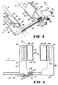
- the open position shown in Figs. 3, 4, and 5, the body portions 22 are spaced apart from each other.
- the connecting means allows each body portion 22 to rotate at least partially about its axis of rotation R.
- Each of the body portions 22 is rotatable between a first position and a second position, which are shown in Figs. 1 and 2, respectively.
- first position at least a section of the body portion 22-here the first section 34 of the blade 20-is disposed above or at the same height as its axis of rotation R.
- second position a portion of that section which was previously disposed above or at the same height as the axis of rotation R is now disposed below that axis of rotation R, as shown in Figs. 2, 3, and 5.
- the contact side 30 of each body portion 22 preferably is oriented to engage one rib B.
- each of the connecting means comprises a support member 40, which has a lateral edge 42 and a longitudinal edge 44, and a hinge 46 that rotatingly connects a portion of the support member 40 to a portion of one body portion 22 adjacent its top edge 24.
- a hinge 46 that rotatingly connects a portion of the support member 40 to a portion of one body portion 22 adjacent its top edge 24.
- Each hinge 46 rotates the associated body portion 22 about its respective axis of rotation R.
- the rib retractor 10 of the present invention preferably comprises a means for detachably engaging the blades 20 with each other when the blades 20 are in the closed position. Once engaged, both blades 20 are simultaneously rotatable from the first position to the second position as the support members 40 are moved closer toward each other, which is best shown comparing Figs. 1 and 2.
- the preferred detachably engaging means comprises a protrusion 50 disposed on the external side 32 of one of the body portions 22 and an indentation 52 disposed in the external side 32 of the other body portion 22.
- the indentation 52 is of a size to complementarily receive the protrusion 50 therein.
- the blades 20 are in the preferred position for use as a rib retractor 10 because they are disposed to have an hour glass configuration in cross section. Referring now to Fig. 3, the blades 20 are disposed to cup the ribs B so that the ribs B contact a portion of the curved portion 38 of the blades 20.
- the rib retractor 10 preferably further comprises a means for locking each of the body portions 22 in that orientation.
- each of the support members 40 has a detent 60 therein and each of the connecting means further comprises a locking member 62 connected to each blade 20.
- the locking member 62 has a first end 64 pivotally depending from the top edge 24 of one of the body portions 22, such as by a hinge 63, and an opposite second end 66 that complementarily engages the detent 60 in the associated support member 40. With the locking member 62 engaged with the detent 60, the body portion 22 is locked in the second position.
- the locking member 62 securely engages the detent 60 when a force is applied to the contact side 30 of the body portion 22 below the hinge 46, such as when the contact side 30 of the blade 20 contacts the rib B.
- the moving means moves the blades 20 to the open position, the blades 20 remain locked in the second position.
- the body portion 22 is rotatable about axis R.
- the moving means preferably comprises a longitudinally-extending rack 56 having a length and a means for attaching a longitudinal edge 44 of each of the support members 40 to the rack 56.
- At least one of the support members 40 should be movable along a portion of the length of the rack 56 so that the support members 40 are longitudinally movable relative to each other.
- only one of the support members 40 is movable and the other support member 40 is fixedly attached to the rack 56, such as by a weld.
- both of the blades 20 can be movable along a portion of the length of the rack 56.
- the rack 56 preferably has a plurality of teeth 58 longitudinally disposed along at least a portion of its length.
- the attaching means of the support member 40 that is movable along the rack 56 comprises a pinion 70 having a plurality of teeth 72 therein, a means for positioning the pinion 70 relative to the support member 40, and a handle member 74 to rotate the pinion 70.
- the teeth 72 of the pinion 70 matingly engage the teeth 58 of the rack 56 and the positioning means positions the pinion 70 so that its teeth 72 rotatably and movably engage the teeth 58 of the rack 56.
- the handle member 74 has a bottom end 76 fixedly attached to a portion of the pinion 70 so that rotation of the handle member 74 causes the pinion 70 to rotate.
- This rotation of the pinion 70 correspondingly causes the support member 40 to move longitudinally along at least a portion of the length of the rack 56 as the teeth 72 of the pinion 70 engage the teeth 58 of the rack 56.
- Rotation of the handle member 74 is represented by arrows A in Figs. 1 and 2.
- Fig. 1 shows the handle member 74 being rotated to move the support members 40 toward each other and
- Fig. 2 shows rotation so that support members 40 move away from each other.
- the present invention also comprises a means for securing the support member 40 at selected points throughout a range of locations along the length of the rack 56 and a means for selectively disengaging the securing means.
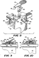
- Figs. 6 and 7 show a first embodiment and Figs. 8-10 show a second embodiment of the selective disengaging means, respectively.
- the aligning member 84 has an exterior surface 86 and defines a bore 88 therethrough.
- the bore 88 is of a size to slidably receive the rack 56 therein.
- the pawl tooth 82 is of a size to be complementarily received intermediate two adjacent teeth 58 of the rack 56.
- a portion of the exterior surface 86 of the attaching member preferably is fixedly attached to the longitudinal edge of the support member 40 and another portion of the exterior surface 86 has a slot 89 therethrough communicating with the bore 88.
- the slot 89 is disposed over the teeth 58 in the rack 56 to allow communication therethrough.
- the securing means also preferably comprises a means for pivotally mounting the pawl arm 80 to a portion of the exterior surface 86 of the aligning member 84 so that the pawl tooth 82 is movable to communicate selectively with the teeth 58 of the rack 56 through the slot 89 of the aligning member 84.
- the pawl tooth 82 can communicate with the teeth 58 in the rack 56 independent of using the slot 89, such as the pawl tooth 82 extending off one end of the attaching member to communicate with the teeth 58.
- the pivotal mounting means is a pin 90 attached to the attachment member about which the pawl arm 80 rotates, although other pivotal mounting means can be used, such as a hinge (not shown), swivel (not shown) and the like.
- the securing means further comprises a means for biasing the pawl tooth 82 of the pawl arm 80 toward the teeth 58 of the rack 56 so that the pawl tooth 82 is capable of selectively engaging the teeth 58 of the rack 56.
- the biasing means is a spring clip 92, or torsional spring, having one end fixedly attached to a portion of the exterior surface 86 of the aligning member 84 and another end fixedly attached to a portion of the pawl arm 80.
- the spring clip 92 biases the pawl tooth 82 into the teeth 58 of the rack 56, as shown in Fig. 6.
- Fig. 7 shows the spring clip 92 biasing the pawl tooth 82 downwardly, although the pawl tooth 82 is not engaging the teeth 58 of the rack 56.
- Other biasing means include a coiled spring (not shown), torque tube (not shown), and the like.
- the first embodiment of the selective disengaging means comprises a pawl detachment member 94 slidably mounted over at least a portion of the exterior surface 86 of the aligning member 84.
- the pawl detachment member 94 is movable between a disengaged position and an engaged position.
- Fig. 7 shows the disengaged position, in which the pawl detachment member 94 is disposed over at least a portion of the slot 89 in the aligning member 84 intermediate the pawl tooth 82 and the teeth 58 of the rack 56 to prevent communication therewith.
- the pawl detachment member 94 which is in the engaged position, is disposed so that the pawl tooth 82 can communicate with the teeth 58 of the rack 56 through the slot 89 of the aligning member 84.
- the second embodiment of the selective disengaging means comprises a barrel member 193, which is rotatably mounted to the aligning member 84 intermediate the pawl arm 80 and the rack 56, and a means for rotating the barrel member 193.
- the barrel member 193 has both a latch surface 194 and a delatch surface 195, which are best shown in Fig. 8.
- the rotating means preferably comprises a lever 197 fixedly attached to a portion of the barrel member 193. This selective disengaging means is preferred compared to the first embodiment because it is easier for the surgeon to move the lever 197 than to slide the pawl detachment member.
- FIG. 9 shows the engaged position, in which the barrel member 193 is rotated so that the latch surface 194 of the barrel contacts the pawl arm 80. Since the latch surface 194 is truncated or lower relative to the delatch surface 195, the pawl tooth 82, urged by the biasing means, communicates with the teeth 58 of the rack 56 through the slot 89 of the aligning member 84. In the disengaged position shown in Fig.
- the delatch surface 195 of the barrel member 193 contacts and raises the pawl arm 80 against the opposing force of the biasing means so that the pawl tooth 82 is prevented from communicating with the teeth 58 of the rack 56.
- the aligning member 84 and its attached support member 40 are freely movable along a portion of the length of the rack 56 since the pawl tooth 82 does not contact the teeth 58 of the rack 56.
- the pawl tooth interfacing with teeth 58 in the rack 56 prevent this free movement.
- the pawl arm 80 is longitudinally oriented and the pawl tooth 82 is disposed intermediate the opposed support member 40 and the pivotal mounting means.
- the support member 40 based on the position of the pivotal mounting means and the biasing means, is movable longitudinally away from the other support member 40 and is prevented from moving toward the other support member 40 while the pawl tooth 82 is engaged with the teeth 58 of the rack 56.
- At least one of the connecting means further comprises a means for rotatably mounting the hinge 46 to the support member 40 so that the hinge 46 and body portion 22 attached thereto are pivotally connected to a portion of the support member 40.
- the rotatably mounting means has an axis of rotation R' substantially perpendicular to the axis R about which the hinge 46 rotates and also substantially perpendicular to the longitudinal axis L of the rib retractor 10.
- the rotatably mounting means comprises a hinge plate 97 into which the detent 60 and the hinge 46 are formed and a swivel 96 having a top end engaging a portion of the hinge plate 97 and an opposite bottom end engaging the support member 40 so that the hinge plate 97 is rotatable relative to the support member 40.
- the rotatably mounting means can entail other means, such as a pin (not shown), another hinge (not shown), or other device to rotatably couple the hinge plate 97 to the support member 40 so that the blade 20 may pivot about axis R.
- the rotatably mounting means allows the blades 20 to conform to the shape of the non-parallel ribs B, which reduces the stresses on the blades 20 and the ribs B of the patient.
- an alternate embodiment of the rib retractor 10 includes a spring 98 that biases the blade 20 and the locking member 62 so that the locking member 62 and the first section 34 of the blade 20 form a desired angle therebetween.
- the angle positions the locking member 62 to engage the detent 60 when the blade 20 is at the second position. This biasing of the locking member 62 relative to the blade 20 allows the surgeon to engage the first end 64 of the locking member 62 with the detent 60 quickly.
- the rib retractor 10 of the present invention can further comprise a latch 99 that is pivotally mounted to each support member 40 adjacent the first section 34 of the blade 20.
- the latch 99 can swing between a securing position, in which the latch 99 holds the blade 20 in the first position, and a release position, in which the latch 99 allows the blade 20 to rotate about its axis of rotation R
- the latches 99 are in the securing position before the blades 20 are rotated from the first position to the second position and then the latches 99 remain in the release position.
- the body portion 22 of the blades 20 are preferably "L" shaped in cross section.
- the first section 34 is substantially parallel to the longitudinal axis L of the rib retractor 10 and the second section 36 depends downwardly therefrom and, when in the second position, the first and second sections 34, 36 are rotated downwardly approximately forty-five degrees from the first position.
- This blade 20 design provides many advantages for use in thoracic surgery.
- the hour glass profile allows greater access through the incision and into the body, specifically the intercostal area of the patient, than other prior art designs.
- the design of the blades 20 also requires less spreading of the ribs B to access the intercostal area to operate than other designs. Accordingly, with less separation required, there is less invasion into the body and less trauma to the intercostal spaces.
- the blades 20 thus result in less damage to arteries, veins, and nerves during a surgical procedure.
- the advantageous blade design works in conjunction with the rib retractor 10 rotating from the first position to the second position.
- the surgeon makes a small incision initially instead of a larger one required for prior art devices.
- the surgeon then places the rib retractor 10 on the person, as shown in Fig. 1.
- the surgeon turns the handle member 74 so that the support members 40 move toward each other, thereby causing the blades 20 to rotate from the first position to the second position, as shown in Fig. 2.
- the second section 36 of the blades 20 move inwardly into the incision and can be locked in the second position.
- the incision would have to be wider to initially insert the blades 20 directly into it when in the second position. And, once the blades 20 rotate to the second position, they provide the greatest access with the least trauma.
Landscapes
- Health & Medical Sciences (AREA)
- Life Sciences & Earth Sciences (AREA)
- Surgery (AREA)
- Heart & Thoracic Surgery (AREA)
- Engineering & Computer Science (AREA)
- Biomedical Technology (AREA)
- Nuclear Medicine, Radiotherapy & Molecular Imaging (AREA)
- Medical Informatics (AREA)
- Molecular Biology (AREA)
- Animal Behavior & Ethology (AREA)
- General Health & Medical Sciences (AREA)
- Public Health (AREA)
- Veterinary Medicine (AREA)
- Surgical Instruments (AREA)
Claims (14)
- Vorrichtung (10) mit einer Längsachse, wobei die Vorrichtung umfasst:a) ein Paar stumpfer Klingen (20), wobei jede der Klingen (20) einen Körperabschnitt (22) mit einer oberen Kante (24), einer Kontaktseite (30) und einer gegenüberliegenden äußeren Seite (32) umfasst;b) eine Einrichtung, die die Klingen (20) relativ zueinander entlang der Längsachse (L) der Vorrichtung zwischen einer geschlossenen Position, in der Abschnitte der äußeren Seite (32) jedes der Körperabschnitte (22) miteinander in Kontakt kommen, und einer offenen Position, in der die Körperabschnitte (22) voneinander beabstandet sind, bewegt;c) eine Einrichtung, die den Körperabschnitt (22) jeder der Klingen (20) mit der Bewegungseinrichtung verbindet, so dass die Körperabschnitte (22) wenigstens teilweise um eine Achse (R) im Wesentlichen senkrecht zu der Längsachse (L) der Vorrichtung gedreht werden können, wobei sich jeder der Körperabschnitte (22) zwischen einer ersten Position, in der wenigstens ein Teil des Körperabschnitts (22) über der Achse (R), um die sich der Körperabschnitt dreht, oder in der gleichen Höhe wie diese angeordnet ist, und einer zweiten Position dreht, in der ein Abschnitt des Teils, der über der Drehachse oder in der gleichen Höhe wie diese angeordnet ist, unter der Drehachse (R) angeordnet ist;
dadurch gekennzeichnet, dass
die Vorrichtung des Weiteren umfasst:d) eine Einrichtung (50, 52), die die Klingen (20) lösbar miteinander in Eingriff bringt, wenn sich die Klingen (20) in der geschlossenen Position befinden, so dass sich beide Klingen gleichzeitig aus der ersten Position an die zweite Position drehen, wenn die Klingen aufeinander zubewegt werden, nachdem sie miteinander in Eingriff gebracht worden sind. - Vorrichtung nach Anspruch 1, wobei die Einrichtung zum Herstellen von lösbarem Eingriff einen Vorsprung (50) an der äußeren Seite (32) eines der Körperabschnitte (22) und eine Vertiefung (52) an der äußeren Seite (32) des anderen der Körperabschnitte (22) umfasst und die Vertiefung eine Größe hat, durch die sie den Vorsprung komplementär aufnimmt, wobei, wenn sich die Klingen (20) aus der offenen Position in die geschlossene Position bewegen, der Vorsprung mit der Vertiefung in Eingriff kommt.
- Vorrichtung nach Anspruch 1, wobei jede der Verbindungseinrichtungen umfasst:a) ein Trageelement (40) mit einer Längskante (44) undb) ein Gelenk (46), das einen Abschnitt des Trageelementes (40) drehbar mit einem Abschnitt des dazugehörigen Körperabschnitts (22) an die obere Kante desselben (24) angrenzend verbindet, wobei das Gelenk (46) eine Achse hat, die entlang der Achse (R) angeordnet ist, um die sich der Körperabschnitt dreht.
- Vorrichtung nach Anspruch 3, wobei die Bewegungseinrichtung umfasst:a) eine sich in Längsrichtung erstreckende Zahnstange (56) mit einer Länge undb) eine Einrichtung zum Anbringen der entsprechenden Längskante (44) jedes der Trageelemente (40) an der Zahnstange (56), wobei wenigstens eines der Trageelemente (40) an einem Abschnitt der Länge der Zahnstange (56) entlang bewegt werden kann, so dass die Trageelemente in Längsrichtung relativ zueinander bewegt werden können.
- Vorrichtung nach Anspruch 4, wobei die Zahnstange (56) eine Vielzahl von Zahnabschnitten (58) aufweist, die in Längsrichtung entlang wenigstens eines Abschnitts ihrer Länge daran angeordnet sind, und
wobei die Anbringungseinrichtung wenigstens eines der Trageelemente umfasst:a) ein Ritzel (70) mit einer Vielzahl von Zähnen (72) daran, wobei die Zähne (72) eine Größe haben, durch die sie passend mit den Zähnen (58) der Zahnstange (56) in Eingriff kommen,b) eine Einrichtung (82), die das Ritzel (70) relativ zu dem Trageelement (40) fest positioniert, wobei die Zähne (72) des Ritzels (70) drehbar und beweglich mit den Zähnen (58) der Zahnstange (56) in Eingriff kommen, undc) ein Griffelement (74) mit einem unteren Ende (76), das fest an einem Abschnitt des Ritzels (70) angebracht ist, so dass Drehung des Griffelementes (74) bewirkt, dass sich das Ritzel (70) dreht, was entsprechend bewirkt, dass sich das Trageelement (40) in Längsrichtung entlang wenigstens eines Abschnitts der Länge der Zahnstange (56) bewegt. - Vorrichtung nach Anspruch 5, wobei die Anbringungseinrichtung des Weiteren umfasst:a) eine Einrichtung zum Befestigen des Trageelementes (40) an ausgewählten Punkten über einen Bereich von Längspositionen entlang der Länge der Zahnstange (56) undb) eine Einrichtung zum selektiven Trennen der Befestigungseinrichtungen.
- Vorrichtung nach Anspruch 6, wobei die Befestigungseinrichtung umfasst:wobei die selektiv trennende Einrichtung ein Sperrklinken-Löseelement (94) umfasst, das verschiebbar über wenigstens einem Abschnitt der äußeren Fläche (86) des Ausrichtelementes (84) angebracht ist, und das Sperrklinken-Löseelement (94) zwischen einer Trennposition, in der das Sperrklinken-Löseelement (94) über wenigstens einem Abschnitt des Schlitzes (89) in dem Ausrichtelement (84) angeordnet ist, so dass das Sperrklinken-Löseelement (94) zwischen dem Sperrklinkenzahn (82) und den Zähnen (58) der Zahnstange (56) angeordnet ist, um Verbindung damit zu verhindern, und einer Eingriffsposition bewegt werden kann, in der das Sperrklinken-Löseelement (84) so angeordnet ist, dass der Sperrklinkenzahn (82) durch den Schlitz (89) des Ausrichtelementes (84) hindurch mit den Zähnen (58) der Zahnstange (56) in Verbindung kommt.a) ein Ausrichtelement (84) mit einer äußeren Fläche, das eine Bohrung durch selbiges hindurch aufweist, wobei die Bohrung (88) eine Größe hat, durch die sie die Zahnstange (56) verschiebbar aufnimmt, ein Abschnitt der äußeren Fläche (86) fest an dem Trageelement (40) angebracht ist und ein anderer Abschnitt der äußeren Fläche (86) einen Schlitz (89) aufweist, der mit der Bohrung (88) in Verbindung steht, wobei der Schlitz (89) über den Zähnen (58) in der Zahnstange (56) angeordnet ist;b) einen Sperrklinkenarm (80) mit einem Sperrklinkenzahn (82), wobei der Sperrklinkenarm (82) eine Größe hat, durch die er komplementär zwischen zwei benachbarten Zähnen (58) der Zahnstange (56) aufgenommen wird;c) eine Einrichtung zum schwenkbaren Anbringen des Sperrklinkenarms (80) an einem Abschnitt der äußeren Fläche (86) des Ausrichtelementes (84), so dass die Sperrklinke (82) bewegt werden kann, um durch den Schlitz (89) des Ausrichtelementes (84) hindurch mit den Zähnen (58) der Zahnstange (56) in Verbindung zu kommen, undd) eine Einrichtung (92), die den Sperrklinkenzahn (82) des Sperrklinkenarms (80) auf die Zähne der Zahnstange zu spannt, so dass der Sperrklinkenzahn selektiv mit den Zähnen der Zahnstange in Eingriff kommen kann, und
- Vorrichtung nach Anspruch 7, wobei der Sperrklinkenarm (80) längs ausgerichtet ist und der Sperrklinkenzahn (82) zwischen dem anderen Trageelement (40) und der Schwenkanbringungseinrichtung angeordnet ist, so dass, wenn der Sperrklinkenzahn (82) mit den Zähnen (58) der Zahnstange (56) in Eingriff kommt, das Trageelement (40) in Längsrichtung von dem anderen Trageelement (40) wegbewegt werden kann und daran gehindert wird, sich auf das andere Trageelement (40) zu zu bewegen.
- Vorrichtung nach Anspruch 3, dass des Weiteren eine Einrichtung (62) zum Arretieren jedes der Körperabschnitte (22) in der zweiten Positionen umfasst.
- Vorrichtung nach Anspruch 9, wobei jedes der Trageelemente (22) eine Einrasteinrichtung (60) darin aufweist und jede der Verbindungseinrichtungen des Weiteren ein Arretierelement (62) umfasst, das eine erstes Ende (64), das schwenkbar von der oberen Kante (24) eines entsprechenden der Körperabschnitte (22) der Klingen (20) herabhängt, sowie ein gegenüberliegendes zweites Ende (66) hat, wobei das zweite Ende (66) komplementär mit der Einrasteinrichtung (60) in einem entsprechenden der Trageelemente (40) in Eingriff kommt, um den Körperabschnitt (22) in der zweiten Position zu positionieren, und, wenn das zweite Ende (66) von der Einrasteinrichtung (60) getrennt wird, der Hauptkörperabschnitt (22) an die erste Position gedreht werden kann.
- Vorrichtung nach Anspruch 3, wobei wenigstens eine der Verbindungseinrichtungen des Weiteren eine Einrichtung zum drehbaren Anbringen des Gelenkes (46) an dem Trageelement (40) umfasst, so dass das Gelenk (46) und der daran angebrachte Körperabschnitt (22) schwenkbar mit einem Abschnitt des Trageelementes (40) verbunden sind und die Schwenkanbringungseinrichtung eine Drehachse (R') senkrecht sowohl zu der Achse (R), um die sich das Gelenk dreht, als auch senkrecht zu der Längsachse (L) der Vorrichtung (10) hat.
- Vorrichtung nach Anspruch 11, wobei die Drehanbringungseinrichtung ein Scharnier (96) umfasst, das ein oberes Ende, das an einem Abschnitt des Gelenks (46) angebracht ist, und ein gegenüberliegendes unteres Ende hat, das an dem Trageelement (40) angebracht ist.
- Vorrichtung nach Anspruch 1, wobei der Körperabschnitt (22) der Klinge im Querschnitt entlang einer Ebene im Wesentlichen parallel zur Längsachse (L) der Vorrichtung (10) "L"-förmig ist, so dass jeder der Körperabschnitte (22) einen ersten Teil (34) und einen zweiten Teil (36) hat, wobei der zweite Teil (36) im Wesentlichen senkrecht zu dem ersten Teil (34) ausgerichtet ist,
wobei der erste Teil (34), wenn er sich in der ersten Position befindet, im Wesentlichen parallel zu der Längsachse (L) der Vorrichtung (10) ist und der zweite Teil (36) davon nach unten vorsteht, und
wobei der erste und der zweite Teil (34, 36), wenn sie sich in der zweiten Position befinden, gegenüber der ersten Position um ungefähr 45° nach unten gedreht sind. - Vorrichtung nach Anspruch 1 oder 2, wobei die Vorrichtung ein Rippenretraktor (10) ist, der so eingerichtet ist, dass er mit benachbarten Rippen (B) einer Person durch einen Einschnitt hindurch in Kontakt kommt, und die Kontaktseite (30) so eingerichtet ist, dass sie mit einer ausgewählten der Rippen (B) der Person in Kontakt kommt und
wobei in der ersten Position wenigstens ein Teil des Körperabschnitts (22) über dem Einschnitt der Person angeordnet werden kann und in der zweiten Position wenigstens ein Teil des Körperabschnitts (22) in dem Einschnitt angeordnet werden kann und die Kontaktseite (30) des Körperabschnitts (22) so ausgerichtet ist, dass sie mit einer Rippe (B) in Eingriff kommt.
Applications Claiming Priority (5)
| Application Number | Priority Date | Filing Date | Title |
|---|---|---|---|
| US08/719,612 US5931778A (en) | 1996-09-25 | 1996-09-25 | Rib retractor |
| US719612 | 1996-09-25 | ||
| US794232 | 1997-01-30 | ||
| US08/794,232 US5788630A (en) | 1996-09-25 | 1997-01-30 | Rib retractor |
| PCT/US1997/017511 WO1998012960A1 (en) | 1996-09-25 | 1997-09-25 | Rib retractor |
Publications (3)
| Publication Number | Publication Date |
|---|---|
| EP1006887A1 EP1006887A1 (de) | 2000-06-14 |
| EP1006887A4 EP1006887A4 (de) | 2001-08-08 |
| EP1006887B1 true EP1006887B1 (de) | 2005-06-15 |
Family
ID=27110102
Family Applications (1)
| Application Number | Title | Priority Date | Filing Date |
|---|---|---|---|
| EP97909893A Expired - Lifetime EP1006887B1 (de) | 1996-09-25 | 1997-09-25 | Rippenretraktor |
Country Status (6)
| Country | Link |
|---|---|
| US (1) | US5788630A (de) |
| EP (1) | EP1006887B1 (de) |
| AU (1) | AU4740097A (de) |
| CA (1) | CA2266740A1 (de) |
| DE (1) | DE69733577T2 (de) |
| WO (1) | WO1998012960A1 (de) |
Cited By (2)
| Publication number | Priority date | Publication date | Assignee | Title |
|---|---|---|---|---|
| EP4346626A4 (de) * | 2021-05-26 | 2025-03-12 | James Carr | Wirbelsäulenretraktorklinge und zugehörige retraktorvorrichtung |
| EP4346628A4 (de) * | 2021-05-26 | 2025-05-07 | James Carr | Wirbelsäulenretraktorklinge und zugehörige retraktorvorrichtung und verfahren |
Families Citing this family (56)
| Publication number | Priority date | Publication date | Assignee | Title |
|---|---|---|---|---|
| US5944658A (en) * | 1997-09-23 | 1999-08-31 | Koros; Tibor B. | Lumbar spinal fusion retractor and distractor system |
| US6033425A (en) * | 1997-11-12 | 2000-03-07 | Genzyme Corporation | Lifting rib retractor |
| US5951466A (en) * | 1998-04-13 | 1999-09-14 | Viamedics, Llc | Self-seating surgical access device and method of gaining surgical access to a body cavity |
| US5928139A (en) * | 1998-04-24 | 1999-07-27 | Koros; Tibor B. | Retractor with adjustable length blades and light pipe guides |
| US6746396B1 (en) | 1999-04-13 | 2004-06-08 | Viamedics, Llc | Self-seating surgical access device and method of use |
| US6258023B1 (en) | 1999-07-08 | 2001-07-10 | Chase Medical, Inc. | Device and method for isolating a surface of a beating heart during surgery |
| USD465025S1 (en) | 1999-12-10 | 2002-10-29 | Viamedics, Llc | Soft tissue compression shield |
| US6312377B1 (en) | 2000-04-06 | 2001-11-06 | Viamedics, Llc | Soft tissue compression shield and method of retracting tissue |
| US6986772B2 (en) * | 2001-03-01 | 2006-01-17 | Michelson Gary K | Dynamic lordotic guard with movable extensions for creating an implantation space posteriorly in the lumbar spine |
| FR2821543B1 (fr) * | 2001-03-01 | 2003-05-30 | Stryker Spine Sa | Ancillaire a cremaillere pour le reglage d'un systeme d'osteosynthese rachidienne |
| WO2002069891A2 (en) | 2001-03-01 | 2002-09-12 | Michelson Gary K | Dynamic lordotic guard with movable extensions for creating an implantation space posteriorly in the lumbar spine and method for use thereof |
| US6896680B2 (en) | 2001-03-01 | 2005-05-24 | Gary K. Michelson | Arcuate dynamic lordotic guard with movable extensions for creating an implantation space posteriorly in the lumbar spine |
| US7261688B2 (en) * | 2002-04-05 | 2007-08-28 | Warsaw Orthopedic, Inc. | Devices and methods for percutaneous tissue retraction and surgery |
| US7473222B2 (en) * | 2002-06-26 | 2009-01-06 | Warsaw Orthopedic, Inc. | Instruments and methods for minimally invasive tissue retraction and surgery |
| US6945933B2 (en) * | 2002-06-26 | 2005-09-20 | Sdgi Holdings, Inc. | Instruments and methods for minimally invasive tissue retraction and surgery |
| US7654954B1 (en) * | 2002-07-03 | 2010-02-02 | Boss Instruments Ltd., Inc. | Surgical retractor clamp connectable to an arm of the retractor |
| US7014608B2 (en) | 2002-12-13 | 2006-03-21 | Synthes Spine Company, Lp | Guided retractor and methods of use |
| US20040127773A1 (en) * | 2002-12-31 | 2004-07-01 | Ethicon, Inc. | Curved rack retractor |
| US7338442B2 (en) * | 2003-04-02 | 2008-03-04 | Peak Performance Company | Crank retractor handle |
| US7776047B2 (en) | 2003-04-09 | 2010-08-17 | Depuy Spine, Inc. | Guide for spinal tools, implants, and devices |
| US7909829B2 (en) | 2003-06-27 | 2011-03-22 | Depuy Spine, Inc. | Tissue retractor and drill guide |
| US7416553B2 (en) * | 2003-04-09 | 2008-08-26 | Depuy Acromed, Inc. | Drill guide and plate inserter |
| US7935123B2 (en) | 2003-04-09 | 2011-05-03 | Depuy Acromed, Inc. | Drill guide with alignment feature |
| US7909848B2 (en) | 2003-06-27 | 2011-03-22 | Depuy Spine, Inc. | Tissue retractor and guide device |
| US20050021040A1 (en) * | 2003-07-21 | 2005-01-27 | Rudolf Bertagnoli | Vertebral retainer-distracter and method of using same |
| US7144368B2 (en) | 2003-11-26 | 2006-12-05 | Synthes Spine Company, Lp | Guided retractor and methods of use |
| US20050203532A1 (en) * | 2004-03-12 | 2005-09-15 | Sdgi Holdings, Inc. | Technique and instrumentation for intervertebral prosthesis implantation using independent landmarks |
| US7270632B2 (en) * | 2004-09-03 | 2007-09-18 | Santilli Albert N | Surgical retractor having lifting capability |
| US9622732B2 (en) | 2004-10-08 | 2017-04-18 | Nuvasive, Inc. | Surgical access system and related methods |
| US7695267B2 (en) * | 2006-05-16 | 2010-04-13 | Dynaflex International | Rib forming apparatus and method |
| US20080262494A1 (en) * | 2007-04-17 | 2008-10-23 | Warsaw Orthopedic, Inc. | Spinal tool |
| JP5174167B2 (ja) * | 2007-07-26 | 2013-04-03 | グラフィック パッケージング インターナショナル インコーポレイテッド | 保持機能付運搬具 |
| EP2228014A1 (de) | 2009-03-13 | 2010-09-15 | Cardio Life Research S.A. | Rippenretraktor |
| US8540628B2 (en) | 2010-02-12 | 2013-09-24 | Covidien Lp | Expandable thoracic access port |
| US8579810B2 (en) * | 2010-02-12 | 2013-11-12 | Covidien Lp | Expandable thoracic access port |
| US8777849B2 (en) | 2010-02-12 | 2014-07-15 | Covidien Lp | Expandable thoracic access port |
| US8574155B2 (en) * | 2010-02-12 | 2013-11-05 | Covidien Lp | Expandable surgical access port |
| US8961408B2 (en) * | 2010-08-12 | 2015-02-24 | Covidien Lp | Expandable surgical access port |
| US8864658B2 (en) | 2010-08-12 | 2014-10-21 | Covidien Lp | Expandable surgical access port |
| US9247955B2 (en) | 2010-08-12 | 2016-02-02 | Covidien Lp | Thoracic access port |
| US8597180B2 (en) | 2010-08-12 | 2013-12-03 | Covidien Lp | Expandable thoracic access port |
| US9119665B2 (en) | 2011-03-21 | 2015-09-01 | Covidien Lp | Thoracic access port including foldable anchor |
| US9039610B2 (en) | 2011-05-19 | 2015-05-26 | Covidien Lp | Thoracic access port |
| DE102011053938A1 (de) * | 2011-09-26 | 2013-03-28 | Aesculap Ag | Chirurgisches Retraktionssystem |
| DE102011117413A1 (de) * | 2011-11-02 | 2013-05-02 | Aesculap Ag | Atraumatische Sternumsplatte |
| CA2797624A1 (en) | 2011-12-07 | 2013-06-07 | Covidien Lp | Thoracic access assembly |
| US20130237769A1 (en) | 2012-03-12 | 2013-09-12 | Innovative Cardiac Technologies | Sternal Retractor |
| DE102013101552A1 (de) | 2013-02-15 | 2014-08-21 | Fehling Instruments Gmbh & Co. Kg | Spreizer für die Herz- und Thoraxchirurgie |
| CN103126754A (zh) * | 2013-03-26 | 2013-06-05 | 江苏荷普医疗器械有限公司 | 颈椎撑开器 |
| US9848863B2 (en) | 2015-02-25 | 2017-12-26 | Globus Medical, Inc | Surgical retractor systems and methods |
| US9700293B2 (en) | 2015-08-18 | 2017-07-11 | Globus Medical, Inc. | Devices and systems for surgical retraction |
| CA3059406A1 (en) * | 2016-11-23 | 2018-05-31 | Dignity Health | Non-metallic retractor device with a ratchet arm |
| US10987128B2 (en) | 2017-03-22 | 2021-04-27 | Covidien Lp | Cannula assembly |
| US11141191B2 (en) | 2020-01-15 | 2021-10-12 | Covidien Lp | Surgical access assembly |
| US12251130B2 (en) | 2021-05-03 | 2025-03-18 | Covidien Lp | Surgical access device having a balloon and methods for manufacturing the same |
| CN118526240B (zh) * | 2024-06-26 | 2024-12-20 | 天津灵睿科技发展有限公司 | 一种医用切口保护器 |
Family Cites Families (19)
| Publication number | Priority date | Publication date | Assignee | Title |
|---|---|---|---|---|
| FR473451A (fr) * | 1914-06-15 | 1915-01-13 | Pierre Antoine Gentile | Écarteur à écartement parallèle perfectionné |
| US1706500A (en) * | 1927-08-01 | 1929-03-26 | Henry J Smith | Surgical retractor |
| US4156424A (en) * | 1978-05-01 | 1979-05-29 | Burgin Kermit H | Locking adjustable speculum |
| US4239036A (en) * | 1979-05-29 | 1980-12-16 | Krieger Abbott J | Surgical retractor |
| US4627421A (en) * | 1984-08-03 | 1986-12-09 | Symbas Panagiotis N | Sternal retractor |
| US4726356A (en) * | 1985-11-12 | 1988-02-23 | Kapp Surgical Instrument, Inc. | Cardiovascular and thoracic retractor |
| FR2599238B1 (fr) * | 1986-05-28 | 1988-08-19 | Delacroix Chevalier Sa | Ecarteur sternal. |
| US4747394A (en) * | 1986-10-08 | 1988-05-31 | Watanabe Orthopedic Systems, Inc. | Spinal retractor |
| US4852552A (en) * | 1987-09-03 | 1989-08-01 | Pilling Co. | Sternal retractor |
| US5052373A (en) * | 1988-07-29 | 1991-10-01 | Michelson Gary K | Spinal retractor |
| SE8802904D0 (sv) * | 1988-08-16 | 1988-08-16 | Mogens Bugge | Dr mogens bugge's mammaria hake |
| DE8813652U1 (de) * | 1988-10-31 | 1988-12-15 | Waldemar Link Gmbh & Co, 2000 Hamburg | Wundspreizer |
| US4989587A (en) * | 1989-04-26 | 1991-02-05 | Farley Daniel K | Sternal retractor |
| US5067477A (en) * | 1989-08-01 | 1991-11-26 | Codman & Shurtleff, Inc. | Low wear bearing for a surgical retractor |
| US5167223A (en) * | 1989-09-08 | 1992-12-01 | Tibor Koros | Heart valve retractor and sternum spreader surgical instrument |
| US5088472A (en) * | 1990-04-04 | 1992-02-18 | Mehdi Fakhrai | Retractor |
| US5365921A (en) * | 1993-01-22 | 1994-11-22 | Bookwalter John R | Flip-up sternal retractor |
| US5616117A (en) * | 1995-08-03 | 1997-04-01 | Ohio Medical Instrument Company, Inc. | Self locking surgical retractor |
| CA2198036C (en) * | 1996-02-20 | 2000-12-05 | Charles S. Taylor | Access platform for internal mammary dissection |
-
1997
- 1997-01-30 US US08/794,232 patent/US5788630A/en not_active Expired - Fee Related
- 1997-09-25 AU AU47400/97A patent/AU4740097A/en not_active Abandoned
- 1997-09-25 DE DE69733577T patent/DE69733577T2/de not_active Expired - Fee Related
- 1997-09-25 EP EP97909893A patent/EP1006887B1/de not_active Expired - Lifetime
- 1997-09-25 WO PCT/US1997/017511 patent/WO1998012960A1/en not_active Ceased
- 1997-09-25 CA CA002266740A patent/CA2266740A1/en not_active Abandoned
Cited By (2)
| Publication number | Priority date | Publication date | Assignee | Title |
|---|---|---|---|---|
| EP4346626A4 (de) * | 2021-05-26 | 2025-03-12 | James Carr | Wirbelsäulenretraktorklinge und zugehörige retraktorvorrichtung |
| EP4346628A4 (de) * | 2021-05-26 | 2025-05-07 | James Carr | Wirbelsäulenretraktorklinge und zugehörige retraktorvorrichtung und verfahren |
Also Published As
| Publication number | Publication date |
|---|---|
| EP1006887A4 (de) | 2001-08-08 |
| DE69733577T2 (de) | 2006-05-18 |
| US5788630A (en) | 1998-08-04 |
| WO1998012960A1 (en) | 1998-04-02 |
| EP1006887A1 (de) | 2000-06-14 |
| CA2266740A1 (en) | 1998-04-02 |
| DE69733577D1 (de) | 2005-07-21 |
| AU4740097A (en) | 1998-04-17 |
Similar Documents
| Publication | Publication Date | Title |
|---|---|---|
| EP1006887B1 (de) | Rippenretraktor | |
| US5931778A (en) | Rib retractor | |
| US7931589B2 (en) | Surgical retractor device and related methods | |
| US7494463B2 (en) | Retractor and distractor system for use in anterior cervical disc surgery | |
| US6416468B2 (en) | Method of retracting a portion of a patient's body | |
| US7922658B2 (en) | Surgical retractor device and related methods | |
| US8206293B2 (en) | Retractor | |
| US5779629A (en) | Dual axis retractor | |
| CA2309825C (en) | Lifting rib retractor | |
| US6074343A (en) | Surgical tissue retractor | |
| EP1495724B1 (de) | Wundhalter | |
| US7654954B1 (en) | Surgical retractor clamp connectable to an arm of the retractor | |
| EP1269922A1 (de) | Verriegelbarer, gelenkinger und ringförmiger Nähfaden- und Wundhakenhalter | |
| US10420542B2 (en) | Surgical rib retractor | |
| US10603025B2 (en) | Surgical rib retractor | |
| US20040225197A1 (en) | Surgical retractor | |
| US20240188950A1 (en) | Surgical rib retractor | |
| US6979291B1 (en) | Surgical retractor having curved arms | |
| US11517298B2 (en) | Surgical rib retractor | |
| US20070185388A1 (en) | Thorax mounted stabilization platform | |
| WO2016160397A1 (en) | Retractor blade assembly | |
| JP3187929U (ja) | 開創装置 |
Legal Events
| Date | Code | Title | Description |
|---|---|---|---|
| PUAI | Public reference made under article 153(3) epc to a published international application that has entered the european phase |
Free format text: ORIGINAL CODE: 0009012 |
|
| 17P | Request for examination filed |
Effective date: 19990407 |
|
| AK | Designated contracting states |
Kind code of ref document: A1 Designated state(s): DE FR GB |
|
| A4 | Supplementary search report drawn up and despatched |
Effective date: 20010621 |
|
| AK | Designated contracting states |
Kind code of ref document: A4 Designated state(s): DE FR GB |
|
| 17Q | First examination report despatched |
Effective date: 20040123 |
|
| GRAP | Despatch of communication of intention to grant a patent |
Free format text: ORIGINAL CODE: EPIDOSNIGR1 |
|
| GRAS | Grant fee paid |
Free format text: ORIGINAL CODE: EPIDOSNIGR3 |
|
| GRAA | (expected) grant |
Free format text: ORIGINAL CODE: 0009210 |
|
| AK | Designated contracting states |
Kind code of ref document: B1 Designated state(s): DE FR GB |
|
| REG | Reference to a national code |
Ref country code: GB Ref legal event code: FG4D |
|
| REF | Corresponds to: |
Ref document number: 69733577 Country of ref document: DE Date of ref document: 20050721 Kind code of ref document: P |
|
| PG25 | Lapsed in a contracting state [announced via postgrant information from national office to epo] |
Ref country code: GB Free format text: LAPSE BECAUSE OF NON-PAYMENT OF DUE FEES Effective date: 20050925 |
|
| PG25 | Lapsed in a contracting state [announced via postgrant information from national office to epo] |
Ref country code: DE Free format text: LAPSE BECAUSE OF NON-PAYMENT OF DUE FEES Effective date: 20060401 |
|
| ET | Fr: translation filed | ||
| PLBE | No opposition filed within time limit |
Free format text: ORIGINAL CODE: 0009261 |
|
| STAA | Information on the status of an ep patent application or granted ep patent |
Free format text: STATUS: NO OPPOSITION FILED WITHIN TIME LIMIT |
|
| GBPC | Gb: european patent ceased through non-payment of renewal fee |
Effective date: 20050925 |
|
| 26N | No opposition filed |
Effective date: 20060316 |
|
| REG | Reference to a national code |
Ref country code: FR Ref legal event code: ST Effective date: 20080229 |
|
| PG25 | Lapsed in a contracting state [announced via postgrant information from national office to epo] |
Ref country code: FR Free format text: LAPSE BECAUSE OF NON-PAYMENT OF DUE FEES Effective date: 20050930 |