EP1007436B1 - conteneur pour lentilles de contact - Google Patents
conteneur pour lentilles de contact Download PDFInfo
- Publication number
- EP1007436B1 EP1007436B1 EP98936504A EP98936504A EP1007436B1 EP 1007436 B1 EP1007436 B1 EP 1007436B1 EP 98936504 A EP98936504 A EP 98936504A EP 98936504 A EP98936504 A EP 98936504A EP 1007436 B1 EP1007436 B1 EP 1007436B1
- Authority
- EP
- European Patent Office
- Prior art keywords
- cavity
- package
- container
- channel
- previous
- Prior art date
- Legal status (The legal status is an assumption and is not a legal conclusion. Google has not performed a legal analysis and makes no representation as to the accuracy of the status listed.)
- Expired - Lifetime
Links
- 239000012530 fluid Substances 0.000 claims abstract description 44
- 238000004891 communication Methods 0.000 claims abstract description 7
- 210000003813 thumb Anatomy 0.000 claims description 13
- 238000007689 inspection Methods 0.000 claims description 9
- 210000003811 finger Anatomy 0.000 claims description 8
- 230000001012 protector Effects 0.000 claims description 8
- 238000003860 storage Methods 0.000 claims description 6
- 230000005499 meniscus Effects 0.000 claims description 5
- 238000012545 processing Methods 0.000 claims description 3
- 238000000034 method Methods 0.000 description 11
- 239000000463 material Substances 0.000 description 6
- 230000003287 optical effect Effects 0.000 description 4
- 238000007789 sealing Methods 0.000 description 4
- 238000005406 washing Methods 0.000 description 4
- 230000003750 conditioning effect Effects 0.000 description 3
- 230000000887 hydrating effect Effects 0.000 description 3
- 238000004519 manufacturing process Methods 0.000 description 3
- 239000004033 plastic Substances 0.000 description 3
- 229920003023 plastic Polymers 0.000 description 3
- FAPWRFPIFSIZLT-UHFFFAOYSA-M Sodium chloride Chemical compound [Na+].[Cl-] FAPWRFPIFSIZLT-UHFFFAOYSA-M 0.000 description 2
- 230000000994 depressogenic effect Effects 0.000 description 2
- 230000000694 effects Effects 0.000 description 2
- 238000000465 moulding Methods 0.000 description 2
- -1 polyethylene Polymers 0.000 description 2
- 239000004698 Polyethylene Substances 0.000 description 1
- 239000004743 Polypropylene Substances 0.000 description 1
- 239000004793 Polystyrene Substances 0.000 description 1
- 230000004075 alteration Effects 0.000 description 1
- 150000001875 compounds Chemical class 0.000 description 1
- 238000000605 extraction Methods 0.000 description 1
- 210000003414 extremity Anatomy 0.000 description 1
- 238000007667 floating Methods 0.000 description 1
- 238000001746 injection moulding Methods 0.000 description 1
- 238000003780 insertion Methods 0.000 description 1
- 230000037431 insertion Effects 0.000 description 1
- 230000002452 interceptive effect Effects 0.000 description 1
- 238000013508 migration Methods 0.000 description 1
- 230000005012 migration Effects 0.000 description 1
- 229920000573 polyethylene Polymers 0.000 description 1
- 229920001155 polypropylene Polymers 0.000 description 1
- 229920002223 polystyrene Polymers 0.000 description 1
- 238000010926 purge Methods 0.000 description 1
- 239000000523 sample Substances 0.000 description 1
- 239000000243 solution Substances 0.000 description 1
- 239000000126 substance Substances 0.000 description 1
- 238000003856 thermoforming Methods 0.000 description 1
Images

Classifications
-
- B—PERFORMING OPERATIONS; TRANSPORTING
- B65—CONVEYING; PACKING; STORING; HANDLING THIN OR FILAMENTARY MATERIAL
- B65D—CONTAINERS FOR STORAGE OR TRANSPORT OF ARTICLES OR MATERIALS, e.g. BAGS, BARRELS, BOTTLES, BOXES, CANS, CARTONS, CRATES, DRUMS, JARS, TANKS, HOPPERS, FORWARDING CONTAINERS; ACCESSORIES, CLOSURES, OR FITTINGS THEREFOR; PACKAGING ELEMENTS; PACKAGES
- B65D75/00—Packages comprising articles or materials partially or wholly enclosed in strips, sheets, blanks, tubes or webs of flexible sheet material, e.g. in folded wrappers
- B65D75/28—Articles or materials wholly enclosed in composite wrappers, i.e. wrappers formed by associating or interconnecting two or more sheets or blanks
- B65D75/30—Articles or materials enclosed between two opposed sheets or blanks having their margins united, e.g. by pressure-sensitive adhesive, crimping, heat-sealing, or welding
- B65D75/32—Articles or materials enclosed between two opposed sheets or blanks having their margins united, e.g. by pressure-sensitive adhesive, crimping, heat-sealing, or welding one or both sheets or blanks being recessed to accommodate contents
-
- B—PERFORMING OPERATIONS; TRANSPORTING
- B65—CONVEYING; PACKING; STORING; HANDLING THIN OR FILAMENTARY MATERIAL
- B65D—CONTAINERS FOR STORAGE OR TRANSPORT OF ARTICLES OR MATERIALS, e.g. BAGS, BARRELS, BOTTLES, BOXES, CANS, CARTONS, CRATES, DRUMS, JARS, TANKS, HOPPERS, FORWARDING CONTAINERS; ACCESSORIES, CLOSURES, OR FITTINGS THEREFOR; PACKAGING ELEMENTS; PACKAGES
- B65D2585/00—Containers, packaging elements or packages specially adapted for particular articles or materials
- B65D2585/54—Containers, packaging elements or packages specially adapted for particular articles or materials for articles of special shape not otherwise provided for
- B65D2585/545—Contact lenses
Definitions
- the present invention relates to a container, in particular a container for an ophthalmic lens, more especially, a container for a hydrophilic or "soft" contact lens.
- Packages for storing, transporting and dispensing soft contact lenses may comprise a container having a cavity in which the contact lens is housed in a saline solution.
- EP-A-0 223 581 describes such a package.
- the base of the cavity has an inclined surface to aid removal of the lens.
- EP-A-0 604 177 also describes such a package.
- the base of the cavity is concave, and has a radius of curvature which is greater than the radius of curvature of the lens, while being sufficiently small to cause the lens to settle at the lowermost portion of the base, i.e., to centre.
- U.S. Patent No. 3 394 717 describes such a package designed to hold two such lenses.
- Soft contact lenses are generally manufactured by moulding. After moulding, the contact lens is subjected to various hydrating, washing and conditioning processes. In order to minimise handling of the lens, it is desirable to carry out those processes while the lens is in its final package, that is, while the lens is in the container. However, it is then necessary to be able to introduce and to remove treating fluids from the container without damaging the lens.
- Fluid may be introduced to the cavity in which the lens is housed by directing the fluid into the centre of the upturned lens, and then allowing the fluid to overflow into the cavity.
- Contact lenses are usually concavo - convex; in this specification a lens is described as "upturned” when its concave face is uppermost.) This method of fluid introduction avoids damage to the lens, and has the added advantage that it locates the lens at the base of the cavity, and prevents it from floating in the fluid.
- EP-A-0 618 063 describes a nozzle for removing fluid from a container containing a lens.
- the nozzle includes a fluid entrance passage and at least one fluid exit passage.
- the nozzle is placed in sealing contact with the container. Purging fluid is introduced to the container through the fluid entrance passage so that the fluid in the container is force out through the fluid exit passage.
- the arrangement of the fluid entrance passage and the fluid exit passage is such that fluid flow is symmetrical about the central axis of the lens, so preventing migration of the lens from the centre.
- the present invention accordingly provides a package for storage of an ophthalmic lens, the package comprising a container which comprises at least one first cavity containing a fluid and an ophthalmic lens and a second cavity for the removal of the fluid from the or each first cavity, the second cavity being in communication with the or each first cavity, wherein each cavity has an opening, the cross-sectional area of the opening of the or each first cavity being greater than that of the second cavity, and the openings are sealed with a releasable film.
- Fluid removal is carried out by inserting a fluid removal device into the second cavity, either from above or from below, and then withdrawing fluid through the device. Insertion of the device in the second cavity avoids contact between the device and the or each lens, so reducing the possibility of damage to the or each lens.
- the second cavity may also be used to accommodate other devices used in the hydrating, washing or conditioning processes, for example, an ultrasonic probe to agitate the fluid, a device to heat the fluid, or a device to measure the fluid level.
- the second cavity is laterally spaced from the or each first cavity.
- Soft contact lenses are subject to an inspection process as well as to hydrating, washing and conditioning processes.
- an illuminating beam is transmitted through the lens. That beam is then focused on a screen to produce an image of the lens. That image is inspected (by eye or automatically) to determine whether or not the lens contains any irregularities which would make the lens unacceptable for customer use.
- the base of the first cavity has zero optical power when it is flat. However, some curvature of the base is desirable to cause the lens to centre consistently. Accordingly, at least the lower portion of the inner wall of the or each first cavity is preferably concave.
- the inner wall of the or each first cavity advantageously comprises an upper portion and a lower portion, the radius of curvature of the lower portion being greater than the radius of curvature of the upper portion. This allows the first cavity to have a base of low optical power, while being able to contain sufficient fluid to cover the lens.
- the radius of curvature of the lower portion is between 9mm and 35mm. If the radius of curvature of the lower portion is less than 9mm, the lens may not sit with its centre touching the centre of the lower portion. If the radius of curvature is greater than 35mm, the lens may not centre.
- the radius of curvature of the upper portion is such that the maximum diameter of the or each first cavity is between 15mm and 30mm. A diameter that falls within this range allows sufficient volume for washing, while minimising package size.
- the depth of the or each first cavity is between 6mm and 12mm. A depth that falls within this range ensures that the entire lens will be covered by solution, while providing for the user the convenience of a shallow cavity.
- a channel provides the communication between the or each first cavity and the second cavity.
- the discontinuity at their upper edges deflects an illuminating beam being transmitted through the base of the cavity.
- Such deflexion may be interpreted as being caused by an irregularity in the lens being inspected, particularly where the maximum diameter of the first cavity is not much greater than the diameter of the lens.
- the diameter of the or each first cavity is preferably at least 15mm where the bottom of the or each channel joins the or each first cavity. This diameter is slightly larger than the maximum diameter of a contact lens, and thus the channel walls will not extend far enough into the first cavity to cause any disturbance in the lens image during the inspection process.
- the second cavity may be of any depth. Preferably, however, the depth of the second cavity is substantially the same as the depth of the or each first cavity.
- the depth of the channel where it joins the first cavity must be less than the depth of the first cavity.
- the rest of the channel may be of any depth, for example, it may be of the same depth as where the channel joins the first cavity.
- the bottom of the or each channel slopes downward from the or each first cavity to the second cavity.
- the side walls of the or each channel are curved. In other embodiments, the side walls of the or each channel are straight.
- the width of at least a portion of the or each channel may be less than the width of the second cavity.
- the side walls of the channel may provide a constriction midway along the channel's length.
- the channel may be narrower than the second cavity, thus providing a constriction along the whole of the channel's length.
- the width of at least a portion of the or each channel may be approximately equal to the width of the second cavity.
- the side walls of the channel may be straight and of the same width as the second cavity, thus minimising fluid velocity through the channel, and reducing the likelihood of the lens being pulled into the channel.
- the minimum width of the or each channel is between 3mm and 6mm. A width within this range is great enough to permit fluid to flow sufficiently rapidly between the first and second cavities when the fluid removal device is in operation, while preventing the lens from becoming wedged in the channel during or after processing.
- the second cavity may be of any diameter, provided that it is sufficiently wide to receive the fluid removal device.
- the diameter of the second cavity is as small as possible so as to minimise the size of the container, and thus minimise manufacturing costs.
- the container comprises a flange which surrounds the cavities.
- the flange provides a convenient grip for the user on opening the package, and a surface on which to seal a cover for the first and second cavities once a lens has been treated and inspected, and is housed in saline solution, ready for use. To gain access to the lens, the user peels the cover off the resulting package.
- the flange comprises a finger or thumb tab.
- This is a depressed portion of the flange, adapted to receive a finger or a thumb.
- the finger or thumb tab provides enhanced grip for the user, and is particularly useful when the package is being opened in a wet environment.
- the depth of the thumb tab is such that it provides a support for the container. This will improve the stability of the container.
- the flange may comprise one or more grips.
- the grips provide resistance to slippage, and, again, are particularly useful where the package is being opened in a wet environment.
- grips are provided on the finger or thumb tab.
- grips are provided on both sides of the finger or thumb tab.
- the container comprises a protector ring on the outer wall of the or each first cavity. Any damage to the outer wall of the first cavity will affect the inspection process.
- the protector ring reduces such damage.
- the free edge of the protector ring is substantially planar. The protector ring then provides a flat surface for the container to rest on so improving the stability of the container.
- the container is advantageously of plastics material.
- the container may be made by injection moulding or thermoforming.
- the plastics material may be, for example, polyethylene, polypropylene or polystyrene.
- the container may be opaque, translucent or, preferably, transparent in view of the desirability of inspection of the lens in the container, as described above.
- the container may be made of a single material or a multi-layer material so allowing optimisation of the interior and exterior surfaces of the container according to function.
- the inner wall of the or each first cavity comprises a meniscus control means.
- the meniscus control means alters the effect of surface tension between the inner wall of the first cavity and fluid in the first cavity to prevent the meniscus of the fluid from interfering in the inspection process.
- the meniscus control means may comprise an alteration in the surface of the inner wall of the first cavity, for example, treating the surface by flame, corona or chemical treatment, altering the texture of the surface, or including a geometric pattern in the surface.
- the present invention further provides a multi-pack for storage of a plurality of ophthalmic lenses comprising a plurality of containers, each container being constructed according to the broadest aspect of the invention.
- the multi-pack may contain, for example, seven containers for one week's supply of daily disposable lenses.
- the present invention further provides the use of a container for inspection, processing and storage of an ophthalmic lens, the container comprising at least one first cavity for receiving an ophthalmic lens, and a second cavity for the removal of fluid from the or each first cavity, the second cavity being in communication with the or each first cavity.
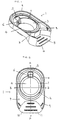
- a container indicated generally by the reference numeral 1 comprises a first circular cavity 2 for receiving a soft contact lens.
- the first cavity 2 is of compound radius, comprising an upper portion 3 and a lower portion 4.
- the container 1 also comprises a second, elliptical cavity 5, and a channel 6 which connects the second cavity 5 with the first cavity 2.
- the depth of the second cavity 5 is the same as the maximum depth of the first cavity 2.
- the channel 6 extends into only the upper portion 3 of the first cavity 2, the bottom half of channel 6 sloping downward from the first cavity 2 to the second cavity 5.
- the side walls of the channel 6 are straight, and the channel 6 is narrower than the second cavity 5.
- the container 1 further comprises a flange indicated generally by the reference numeral 7 comprising a raised sealing rim 8 around the circumference of the first cavity 2 and second cavity 5, and an upstanding outer rim 9 around the circumference of the flange 7.
- the container 1 also comprises a depressed thumb tab 10 having a plurality of ribs 11, and a protector ring 12 underlying the first cavity 2.
- a film (not shown) may be heat sealed to the sealing rim 8 to form a hermetically sealed blister package.
- the rim 9 stiffens the edge of the flange 7, and allows the use of thinner material for the rest of the container, as well as protecting the package in automated handling.
- the thumb tab 10 provides a grip for the consumer.
- a number of ribs (grips) 11 are provided on the upper and lower surfaces of the thumb tab 10.
- the two sets of ribs improve the grip provided by the tab to the user, and the lower ribs co-operate with the planar free edge of the protector ring 12 to provide a flat and stable means for storing and transporting the container.
- the rim 9 and other parts of the container have rounded edges to ease conveyance, and reduce jamming or bridging in automated handling.
- the container 1 may include index marks for use in electronic vision systems, and may be labelled or otherwise coded.
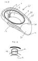
- a second container indicated generally by the reference numeral 21, has cavities 2 and 5, connecting channel 6, sealing rim 8 and protector ring 12, like those of the container 1.
- An outer rim 29 and flange 27 are shaped differently from the corresponding features of the container 1, however, the flange narrowing gradually from a location beside the centre of the first cavity 2, the outer rim 29 being correspondingly curved from that location, the flange terminating in a concave portion 28, at the extremities of which the rim 29 terminates.
- a flat thumb tab 30 slopes down from the concave portion 28, a free edge 31 of the tab 30 being at the level of the edge of the protecting ring 12.
- a third container comprising a second cavity 61 and the adjoining segment of a first cavity 2.
- the channel 62 and the cavity 61 are of the same width, the base (not shown) of the channel 62 sloping down from the first cavity 2 to the second cavity 61 as illustrated in Fig. 3 with reference to the first embodiment.
- the wider channel in comparison with those of the first and second embodiments, provides a lower fluid velocity through the channel when fluid is being removed at a given rate, thereby reducing the likelihood of the lens being pulled into the channel.
- the dimensions of a typical container may be, for example, approximately as follows: height of container 1 11 mm maximum depth of first cavity 2 7 mm radius of curvature of upper portion 3 9 mm radius of curvature of lower portion 4 25 mm maximum diameter of upper portion 3 22 mm depth of second cavity 5 7 mm maximum diameter of second cavity 6 mm depth of channel 6 5.5 mm minimum width of channel 6 5 mm diameter of first cavity 2 where it joins channel 6 18mm
- the first cavity 2 holds approximately 2 ml of fluid.
Landscapes
- Chemical & Material Sciences (AREA)
- Composite Materials (AREA)
- Engineering & Computer Science (AREA)
- Mechanical Engineering (AREA)
- Packages (AREA)
- Purses, Travelling Bags, Baskets, Or Suitcases (AREA)
- Packaging Frangible Articles (AREA)
- Table Devices Or Equipment (AREA)
- Auxiliary Devices For And Details Of Packaging Control (AREA)
- Medical Preparation Storing Or Oral Administration Devices (AREA)
- Glass Compositions (AREA)
Claims (31)
- Conditionnement pour le stockage d'une lentille ophtalmique, le conditionnement comprenant un conteneur (11 21) qui comprend au moins une première cavité (2) contenant un fluide et une lentille ophtalmique et une seconde cavité (5, 61) pour l'évacuation du fluide de la ou chaque première cavité, la seconde cavité étant en communication avec la ou chaque première cavité, dans lequel chaque cavité a une ouverture, la superficie de la section de l'ouverture de la ou chaque première cavité étant plus grande que celle de la seconde cavité, et les ouvertures étant scellées avec une pellicule détachable.
- Conditionnement selon la revendication 1, dans lequel la seconde cavité est espacée latéralement de la ou chaque première cavité.
- Conditionnement selon la revendication 1 ou 2, dans lequel le conteneur comprend au maximum deux premières cavités.
- Conditionnement selon une quelconque des revendications précédentes, dans lequel les ouvertures sont sur la même face du conteneur.
- Conditionnement selon une quelconque des revendications précédentes, dans lequel les ouvertures sont telles que les cavités sont capables de retenir du fluide même quand les ouvertures ne sont pas scellées.
- Conditionnement selon une quelconque des revendications précédentes, dans lequel les ouvertures sont telles que les cavités forment un système fermé quand les ouvertures sont scellées.
- Conditionnement selon une quelconque des revendications précédentes, dans lequel la ou chaque première cavité a une paroi intérieure comprenant une partie supérieure (3) et une partie inférieure (4), la partie inférieure au moins de la paroi intérieure étant concave.
- Conditionnement selon la revendication 7, dans lequel le rayon de courbure de la partie inférieure est plus grand que le rayon de courbure de la partie supérieure.
- Conditionnement selon la revendication 8, dans lequel le rayon de courbure de la partie inférieure fait entre 9 mm et 35 mm.
- Conditionnement selon la revendication 8 ou 9, dans lequel le rayon de courbure de la partie supérieure est tel que le diamètre maximal de la ou chaque première cavité fait entre 15 mm et 30 mm.
- Conditionnement selon une quelconque des revendications précédentes, dans lequel la profondeur de la ou chaque première cavité fait entre 6 mm et 12 mm.
- Conditionnement selon une quelconque des revendications précédentes, dans lequel un canal (6, 62) foumit la communication entre la ou chaque première cavité et la seconde cavité.
- Conditionnement selon la revendication 12, dans lequel le diamètre de la ou chaque première cavité est au moins de 15 mm là où le ou chaque canal rejoint la ou chaque première cavité.
- Conditionnement selon la revendication 13, dans lequel la profondeur de la seconde cavité est sensiblement la même que la profondeur de la ou chaque première cavité.
- Conditionnement selon la revendication 14, dans lequel le fond du ou de chaque canal est incliné vers le bas de la ou chaque première cavité vers la seconde cavité.
- Conditionnement selon la revendication 12 à 15, dans lequel les parois latérales du ou de chaque canal sont courbées.
- Conditionnement selon la revendication 12 à 15, dans lequel les parois latérales du ou de chaque canal sont droites.
- Conditionnement selon la revendication 16 ou 17, dans lequel la largeur d'au moins une partie du ou de chaque canal est moindre que la largeur de la seconde cavité.
- Conditionnement selon la revendication 16 ou 17, dans lequel la largeur d'au moins une partie du ou de chaque canal est approximativement égale à la largeur de la seconde cavité.
- Conditionnement selon la revendication 12 à 19, dans lequel la largeur minimale du ou de chaque canal fait entre 3 mm et 6 mm.
- Conditionnement selon une quelconque des revendications précédentes, dans lequel le conteneur comprend une flasque (7, 27) qui entoure les cavités.
- Conditionnement selon la revendication 21, dans lequel la flasque comprend un onglet ou une patte (10, 30).
- Conditionnement selon la revendication 21 ou la revendication 22, dans lequel la flasque comprend un ou plusieurs éléments de préhension (11).
- Conditionnement selon la revendication 23, dans lequel des éléments de préhension sont prévus sur l'onglet ou la patte.
- Conditionnement selon la revendication 24, dans lequel des éléments de préhension sont prévus sur les deux côtés de l'onglet ou de la patte.
- Conditionnement selon une quelconque des revendications précédentes, dans lequel le conteneur comprend une bague de protection (12) sur la paroi extérieure de la ou chaque première cavité.
- Conditionnement selon une quelconque des revendications précédentes, dans lequel la paroi intérieure de la ou chaque première cavité comprend un moyen de contrôle méniscoïde.
- Conditionnement multiple pour le stockage d'une pluralité de lentilles ophtalmiques, le conditionnement multiple comprenant une pluralité de conteneurs tels que définis dans la revendication 1.
- Conditionnement multiple selon la revendication 28, dans lequel chaque conteneur est tel que spécifié dans l'une quelconque des revendications 2 à 27.
- Utilisation d'un conteneur pour l'inspection, le traitement et le stockage d'une lentille ophtalmique, le conteneur comprenant au moins une première cavité pour recevoir une lentille ophtalmique et une seconde cavité pour l'évacuation du fluide de la ou chaque première cavité, la seconde cavité étant en communication avec la ou chaque première cavité.
- Utilisation selon la revendication 30, dans laquelle le conteneur est tel que spécifié dans une quelconque des revendications 1 à 27.
Applications Claiming Priority (3)
| Application Number | Priority Date | Filing Date | Title |
|---|---|---|---|
| GB9716118 | 1997-07-30 | ||
| GBGB9716118.6A GB9716118D0 (en) | 1997-07-30 | 1997-07-30 | Container |
| PCT/GB1998/002226 WO1999006300A1 (fr) | 1997-07-30 | 1998-07-27 | Reservoir |
Publications (2)
| Publication Number | Publication Date |
|---|---|
| EP1007436A1 EP1007436A1 (fr) | 2000-06-14 |
| EP1007436B1 true EP1007436B1 (fr) | 2002-04-10 |
Family
ID=10816720
Family Applications (1)
| Application Number | Title | Priority Date | Filing Date |
|---|---|---|---|
| EP98936504A Expired - Lifetime EP1007436B1 (fr) | 1997-07-30 | 1998-07-27 | conteneur pour lentilles de contact |
Country Status (10)
| Country | Link |
|---|---|
| US (1) | US6398018B1 (fr) |
| EP (1) | EP1007436B1 (fr) |
| JP (1) | JP4386569B2 (fr) |
| CN (1) | CN1264347A (fr) |
| AT (1) | ATE215899T1 (fr) |
| AU (1) | AU748922B2 (fr) |
| CA (1) | CA2294920A1 (fr) |
| DE (1) | DE69804812T2 (fr) |
| GB (1) | GB9716118D0 (fr) |
| WO (1) | WO1999006300A1 (fr) |
Families Citing this family (37)
| Publication number | Priority date | Publication date | Assignee | Title |
|---|---|---|---|---|
| US6082533A (en) * | 1998-12-15 | 2000-07-04 | Bausch & Lomb Incorporated | Contact lens package |
| USD500852S1 (en) * | 2001-09-28 | 2005-01-11 | Meagan Medical, Inc. | Container for percutaneous probes |
| GB0126708D0 (en) | 2001-11-07 | 2002-01-02 | Provis Ltd | Packaging for contact lenses |
| US20040004008A1 (en) * | 2002-06-26 | 2004-01-08 | Peck James M. | Contact lens packages |
| BR0317631B1 (pt) * | 2002-12-23 | 2013-09-03 | embalagem para a armazenagem de lentes de contato em uma solução, e método para reduzir a aderência de lentes de contato à sua embalagem | |
| US20050065438A1 (en) * | 2003-09-08 | 2005-03-24 | Miller Landon C.G. | System and method of capturing and managing information during a medical diagnostic imaging procedure |
| US7722808B2 (en) * | 2003-09-12 | 2010-05-25 | Novartis Ag | Method and kits for sterilizing and storing soft contact lenses |
| WO2006061886A1 (fr) * | 2004-12-07 | 2006-06-15 | Menicon Co., Ltd. | Recipient de lentille oculaire et produit d’emballage de recipient de lentille oculaire |
| US20060232766A1 (en) * | 2005-03-31 | 2006-10-19 | Watterson Robert J Jr | Methods of inspecting ophthalmic lenses |
| US20070170075A1 (en) * | 2006-01-23 | 2007-07-26 | Mark Robert Winters | MPSS (Multi-Purpose Solution Saver) contact lense case |
| JP4545724B2 (ja) * | 2006-09-04 | 2010-09-15 | 株式会社カナエ | ブリスターパック |
| US7477366B2 (en) * | 2006-12-07 | 2009-01-13 | Coopervision International Holding Company, Lp | Contact lens blister packages and methods for automated inspection of hydrated contact lenses |
| USD559706S1 (en) | 2007-03-15 | 2008-01-15 | Coopervision International Holding Company, Lp | Contact lens blister package array |
| USD556602S1 (en) | 2006-12-08 | 2007-12-04 | Coopervision International Holding Company, Lp | Contact lens blister package |
| USD556603S1 (en) | 2006-12-08 | 2007-12-04 | Coopervision International Holding Company, Lp | Contact lens blister package |
| WO2012060398A1 (fr) | 2010-11-02 | 2012-05-10 | Toto株式会社 | Objet revêtu d'un photocatalyseur et liquide de revêtement photocatalyseur pour l'objet |
| MY187345A (en) * | 2012-04-23 | 2021-09-22 | Coopervision Int Ltd | Contact lens blister packages |
| US10368621B2 (en) * | 2013-03-15 | 2019-08-06 | Johnson & Johnson Vision Care, Inc. | Contact lens package with reduced lens-package interactions and method of making |
| US9439487B2 (en) | 2013-03-15 | 2016-09-13 | Johnson & Johnson Vision Care, Inc. | Contact lens package with reduced head space |
| MX360133B (es) | 2014-03-31 | 2018-10-23 | Coopervision Int Holding Co Lp | Empaquetado de lentes de contacto y metodos de fabricacion de lentes de contacto empaquetados. |
| JP6129239B2 (ja) * | 2015-06-01 | 2017-05-17 | 株式会社メニコン | コンタクトレンズ容器の製造方法とコンタクトレンズ容器 |
| USD831506S1 (en) * | 2017-09-22 | 2018-10-23 | Johnsonville, Llc | Snack tray |
| US11253035B2 (en) | 2019-01-22 | 2022-02-22 | Coopervision International Holding Company, Lp | Blister package for contact lens |
| US11267643B2 (en) | 2019-01-22 | 2022-03-08 | Coopervision International Limited | Contact lens dispenser |
| US11229266B2 (en) | 2019-01-22 | 2022-01-25 | Coopervision International Limited | Tessellating blister packages for contact lenses |
| US11136176B2 (en) | 2019-01-22 | 2021-10-05 | Coopervision International Limited | Contact lens blister package with lens cradle |
| US11419397B2 (en) | 2019-01-22 | 2022-08-23 | Coopervision International Limited | Push-up contact lens blister package |
| US12053069B2 (en) | 2019-01-22 | 2024-08-06 | Coopervision International Limited | Contact lens blister package with double layer foil component |
| US11649099B2 (en) | 2020-06-23 | 2023-05-16 | Coopervision International Limited | Contact lens packages and methods of use |
| GB2625414B (en) | 2021-07-27 | 2025-06-04 | Coopervision Int Ltd | Connectable contact lens packages for recycling |
| US11655070B2 (en) | 2021-07-27 | 2023-05-23 | Coopervision International Limited | Contact lens blister packages and methods for recycling same |
| TWD222836S (zh) * | 2022-05-25 | 2022-12-21 | 晶碩光學股份有限公司 | 隱形眼鏡包裝盒 |
| TWD222835S (zh) * | 2022-05-25 | 2022-12-21 | 晶碩光學股份有限公司 | 隱形眼鏡容器 |
| GB2605721B (en) | 2022-06-01 | 2023-06-07 | Coopervision Int Ltd | A packaged contact lens |
| WO2023233117A1 (fr) | 2022-06-01 | 2023-12-07 | Coopervision International Limited | Lentille de contact conditionnée |
| USD1062223S1 (en) * | 2022-06-21 | 2025-02-18 | Johnson & Johnson Vision Care, Inc. | Contact lens package |
| USD1061023S1 (en) * | 2022-06-21 | 2025-02-11 | Johnson & Johnson Vision Care, Inc. | Contact lens package |
Family Cites Families (15)
| Publication number | Priority date | Publication date | Assignee | Title |
|---|---|---|---|---|
| US3211503A (en) * | 1963-01-09 | 1965-10-12 | United Carr Inc | Container |
| US3394717A (en) * | 1966-09-20 | 1968-07-30 | Richard G. Hollinger | Contact lens container |
| US3759375A (en) * | 1971-05-21 | 1973-09-18 | J Nappi | Disposable swab-type applicator package |
| AT337088B (de) * | 1975-05-20 | 1977-06-10 | Desinfecta Ges M B H | Verpackung fur pulver, korner und dgl. und verfahren zu ihrer herstellung |
| DE2707841A1 (de) * | 1977-02-23 | 1978-08-24 | Flag Print Ag | Schmierfettkapsel |
| US4337858A (en) * | 1980-03-27 | 1982-07-06 | Ryder International Corporation | Lens case |
| ATE89523T1 (de) | 1985-11-18 | 1993-06-15 | Johnson & Johnson Vision Prod | Verpackung fuer wasseranziehende kontaktlinsen. |
| DK168746B1 (da) * | 1992-07-06 | 1994-05-30 | Tom Buris Nielsen | Fremgangsmåde og etui til desinficering af kontaktlinser |
| NZ250453A (en) * | 1992-12-21 | 1996-12-20 | Johnson & Johnson Vision Prod | Ophthalmic lens package; planar surface with concave bowl for containing lens, sealing sheet covering bowl with lens therein |
| IL108992A (en) | 1993-03-29 | 1997-11-20 | Johnson & Johnson Vision Prod | Solution removal nozzle |
| JPH0739414A (ja) * | 1993-07-29 | 1995-02-10 | Dainippon Printing Co Ltd | コンタクトレンズのケース |
| US5697495A (en) * | 1993-11-02 | 1997-12-16 | Johnson & Johnson Vision Products, Inc. | Packaging arrangement for contact lenses |
| TW295570B (fr) * | 1994-05-04 | 1997-01-11 | Ciba Geigy Ag | |
| US5409104A (en) * | 1994-06-01 | 1995-04-25 | Ciba-Geigy Corporation | Contact lens package having improved access features |
| US5711416A (en) * | 1994-06-15 | 1998-01-27 | Bauman; Robert C. | Disposable contact lens storage container with concave storage recess |
-
1997
- 1997-07-30 GB GBGB9716118.6A patent/GB9716118D0/en not_active Ceased
-
1998
- 1998-07-27 AT AT98936504T patent/ATE215899T1/de not_active IP Right Cessation
- 1998-07-27 DE DE69804812T patent/DE69804812T2/de not_active Expired - Lifetime
- 1998-07-27 JP JP2000505073A patent/JP4386569B2/ja not_active Expired - Lifetime
- 1998-07-27 AU AU85479/98A patent/AU748922B2/en not_active Ceased
- 1998-07-27 WO PCT/GB1998/002226 patent/WO1999006300A1/fr not_active Ceased
- 1998-07-27 CN CN98807402A patent/CN1264347A/zh active Pending
- 1998-07-27 CA CA002294920A patent/CA2294920A1/fr not_active Abandoned
- 1998-07-27 EP EP98936504A patent/EP1007436B1/fr not_active Expired - Lifetime
-
2000
- 2000-01-27 US US09/492,493 patent/US6398018B1/en not_active Expired - Lifetime
Also Published As
| Publication number | Publication date |
|---|---|
| WO1999006300A1 (fr) | 1999-02-11 |
| DE69804812D1 (de) | 2002-05-16 |
| JP4386569B2 (ja) | 2009-12-16 |
| AU8547998A (en) | 1999-02-22 |
| EP1007436A1 (fr) | 2000-06-14 |
| AU748922B2 (en) | 2002-06-13 |
| US6398018B1 (en) | 2002-06-04 |
| GB9716118D0 (en) | 1997-10-08 |
| JP2001513470A (ja) | 2001-09-04 |
| CN1264347A (zh) | 2000-08-23 |
| ATE215899T1 (de) | 2002-04-15 |
| CA2294920A1 (fr) | 1999-02-11 |
| DE69804812T2 (de) | 2002-11-07 |
Similar Documents
| Publication | Publication Date | Title |
|---|---|---|
| EP1007436B1 (fr) | conteneur pour lentilles de contact | |
| EP2840927B1 (fr) | Emballages-coque pour lentilles de contact | |
| JP2847776B2 (ja) | 多数のパツケージ化コンタクト・レンズのための容器 | |
| US11980265B2 (en) | Blister package for contact lens | |
| US7225919B2 (en) | Packaging for contact lenses | |
| JP5144043B2 (ja) | コンタクトレンズパッケージ | |
| US5704468A (en) | Packaging arrangement for contact lenses | |
| JP2563119B2 (ja) | 多数の包装されたコンタクト・レンズのための容器 | |
| EP0529066B1 (fr) | Boitier de rangement pour verres de contact | |
| US4779754A (en) | Draining lid | |
| US3268068A (en) | Contact lens apparatus | |
| JP2007508882A (ja) | コンタクトレンズケアシステム | |
| EP1035784A1 (fr) | Contenant de stockage pour lentille de contact | |
| JPH0536430Y2 (fr) | ||
| HK1203328B (en) | Contact lens blister packages | |
| JPH0223151Y2 (fr) | ||
| JP2003102808A (ja) | 簡易型哺乳瓶消毒器 | |
| HK1121006B (en) | Contact lens package |
Legal Events
| Date | Code | Title | Description |
|---|---|---|---|
| PUAI | Public reference made under article 153(3) epc to a published international application that has entered the european phase |
Free format text: ORIGINAL CODE: 0009012 |
|
| 17P | Request for examination filed |
Effective date: 20000127 |
|
| AK | Designated contracting states |
Kind code of ref document: A1 Designated state(s): AT BE CH CY DE DK ES FI FR GB GR IE IT LI LU MC NL PT SE |
|
| AX | Request for extension of the european patent |
Free format text: AL PAYMENT 20000127;LT PAYMENT 20000127;LV PAYMENT 20000127;MK PAYMENT 20000127;RO PAYMENT 20000127;SI PAYMENT 20000127 |
|
| GRAG | Despatch of communication of intention to grant |
Free format text: ORIGINAL CODE: EPIDOS AGRA |
|
| 17Q | First examination report despatched |
Effective date: 20010314 |
|
| GRAG | Despatch of communication of intention to grant |
Free format text: ORIGINAL CODE: EPIDOS AGRA |
|
| GRAG | Despatch of communication of intention to grant |
Free format text: ORIGINAL CODE: EPIDOS AGRA |
|
| GRAH | Despatch of communication of intention to grant a patent |
Free format text: ORIGINAL CODE: EPIDOS IGRA |
|
| RAP1 | Party data changed (applicant data changed or rights of an application transferred) |
Owner name: OCULAR SCIENCES INC. |
|
| GRAH | Despatch of communication of intention to grant a patent |
Free format text: ORIGINAL CODE: EPIDOS IGRA |
|
| REG | Reference to a national code |
Ref country code: GB Ref legal event code: IF02 |
|
| GRAA | (expected) grant |
Free format text: ORIGINAL CODE: 0009210 |
|
| AK | Designated contracting states |
Kind code of ref document: B1 Designated state(s): AT BE CH CY DE DK ES FI FR GB GR IE IT LI LU MC NL PT SE |
|
| AX | Request for extension of the european patent |
Free format text: AL PAYMENT 20000127;LT PAYMENT 20000127;LV PAYMENT 20000127;MK PAYMENT 20000127;RO PAYMENT 20000127;SI PAYMENT 20000127 |
|
| LTIE | Lt: invalidation of european patent or patent extension | ||
| PG25 | Lapsed in a contracting state [announced via postgrant information from national office to epo] |
Ref country code: LI Free format text: LAPSE BECAUSE OF FAILURE TO SUBMIT A TRANSLATION OF THE DESCRIPTION OR TO PAY THE FEE WITHIN THE PRESCRIBED TIME-LIMIT Effective date: 20020410 Ref country code: IT Free format text: LAPSE BECAUSE OF FAILURE TO SUBMIT A TRANSLATION OF THE DESCRIPTION OR TO PAY THE FEE WITHIN THE PRESCRIBED TIME-LIMIT;WARNING: LAPSES OF ITALIAN PATENTS WITH EFFECTIVE DATE BEFORE 2007 MAY HAVE OCCURRED AT ANY TIME BEFORE 2007. THE CORRECT EFFECTIVE DATE MAY BE DIFFERENT FROM THE ONE RECORDED. Effective date: 20020410 Ref country code: GR Free format text: LAPSE BECAUSE OF FAILURE TO SUBMIT A TRANSLATION OF THE DESCRIPTION OR TO PAY THE FEE WITHIN THE PRESCRIBED TIME-LIMIT Effective date: 20020410 Ref country code: FI Free format text: LAPSE BECAUSE OF FAILURE TO SUBMIT A TRANSLATION OF THE DESCRIPTION OR TO PAY THE FEE WITHIN THE PRESCRIBED TIME-LIMIT Effective date: 20020410 Ref country code: CH Free format text: LAPSE BECAUSE OF FAILURE TO SUBMIT A TRANSLATION OF THE DESCRIPTION OR TO PAY THE FEE WITHIN THE PRESCRIBED TIME-LIMIT Effective date: 20020410 Ref country code: BE Free format text: LAPSE BECAUSE OF FAILURE TO SUBMIT A TRANSLATION OF THE DESCRIPTION OR TO PAY THE FEE WITHIN THE PRESCRIBED TIME-LIMIT Effective date: 20020410 Ref country code: AT Free format text: LAPSE BECAUSE OF FAILURE TO SUBMIT A TRANSLATION OF THE DESCRIPTION OR TO PAY THE FEE WITHIN THE PRESCRIBED TIME-LIMIT Effective date: 20020410 |
|
| REF | Corresponds to: |
Ref document number: 215899 Country of ref document: AT Date of ref document: 20020415 Kind code of ref document: T |
|
| REG | Reference to a national code |
Ref country code: CH Ref legal event code: EP |
|
| REG | Reference to a national code |
Ref country code: IE Ref legal event code: FG4D |
|
| REF | Corresponds to: |
Ref document number: 69804812 Country of ref document: DE Date of ref document: 20020516 |
|
| PG25 | Lapsed in a contracting state [announced via postgrant information from national office to epo] |
Ref country code: SE Free format text: LAPSE BECAUSE OF FAILURE TO SUBMIT A TRANSLATION OF THE DESCRIPTION OR TO PAY THE FEE WITHIN THE PRESCRIBED TIME-LIMIT Effective date: 20020710 Ref country code: PT Free format text: LAPSE BECAUSE OF FAILURE TO SUBMIT A TRANSLATION OF THE DESCRIPTION OR TO PAY THE FEE WITHIN THE PRESCRIBED TIME-LIMIT Effective date: 20020710 Ref country code: DK Free format text: LAPSE BECAUSE OF FAILURE TO SUBMIT A TRANSLATION OF THE DESCRIPTION OR TO PAY THE FEE WITHIN THE PRESCRIBED TIME-LIMIT Effective date: 20020710 |
|
| PG25 | Lapsed in a contracting state [announced via postgrant information from national office to epo] |
Ref country code: LU Free format text: LAPSE BECAUSE OF NON-PAYMENT OF DUE FEES Effective date: 20020727 |
|
| PG25 | Lapsed in a contracting state [announced via postgrant information from national office to epo] |
Ref country code: CY Free format text: LAPSE BECAUSE OF FAILURE TO SUBMIT A TRANSLATION OF THE DESCRIPTION OR TO PAY THE FEE WITHIN THE PRESCRIBED TIME-LIMIT Effective date: 20020731 |
|
| ET | Fr: translation filed | ||
| REG | Reference to a national code |
Ref country code: CH Ref legal event code: PL |
|
| PG25 | Lapsed in a contracting state [announced via postgrant information from national office to epo] |
Ref country code: ES Free format text: LAPSE BECAUSE OF FAILURE TO SUBMIT A TRANSLATION OF THE DESCRIPTION OR TO PAY THE FEE WITHIN THE PRESCRIBED TIME-LIMIT Effective date: 20021030 |
|
| PG25 | Lapsed in a contracting state [announced via postgrant information from national office to epo] |
Ref country code: NL Free format text: LAPSE BECAUSE OF NON-PAYMENT OF DUE FEES Effective date: 20030201 Ref country code: MC Free format text: LAPSE BECAUSE OF NON-PAYMENT OF DUE FEES Effective date: 20030201 |
|
| PLBE | No opposition filed within time limit |
Free format text: ORIGINAL CODE: 0009261 |
|
| STAA | Information on the status of an ep patent application or granted ep patent |
Free format text: STATUS: NO OPPOSITION FILED WITHIN TIME LIMIT |
|
| NLV4 | Nl: lapsed or anulled due to non-payment of the annual fee |
Effective date: 20030201 |
|
| 26N | No opposition filed |
Effective date: 20030113 |
|
| REG | Reference to a national code |
Ref country code: GB Ref legal event code: 732E |
|
| REG | Reference to a national code |
Ref country code: GB Ref legal event code: 732E |
|
| REG | Reference to a national code |
Ref country code: FR Ref legal event code: TP Ref country code: FR Ref legal event code: CA |
|
| REG | Reference to a national code |
Ref country code: FR Ref legal event code: PLFP Year of fee payment: 19 |
|
| REG | Reference to a national code |
Ref country code: FR Ref legal event code: PLFP Year of fee payment: 20 |
|
| PGFP | Annual fee paid to national office [announced via postgrant information from national office to epo] |
Ref country code: FR Payment date: 20170613 Year of fee payment: 20 |
|
| PGFP | Annual fee paid to national office [announced via postgrant information from national office to epo] |
Ref country code: DE Payment date: 20170719 Year of fee payment: 20 Ref country code: GB Payment date: 20170726 Year of fee payment: 20 |
|
| PGFP | Annual fee paid to national office [announced via postgrant information from national office to epo] |
Ref country code: IE Payment date: 20170710 Year of fee payment: 20 |
|
| REG | Reference to a national code |
Ref country code: DE Ref legal event code: R071 Ref document number: 69804812 Country of ref document: DE |
|
| REG | Reference to a national code |
Ref country code: GB Ref legal event code: PE20 Expiry date: 20180726 |
|
| REG | Reference to a national code |
Ref country code: IE Ref legal event code: MK9A |
|
| PG25 | Lapsed in a contracting state [announced via postgrant information from national office to epo] |
Ref country code: IE Free format text: LAPSE BECAUSE OF EXPIRATION OF PROTECTION Effective date: 20180727 |
|
| PG25 | Lapsed in a contracting state [announced via postgrant information from national office to epo] |
Ref country code: GB Free format text: LAPSE BECAUSE OF EXPIRATION OF PROTECTION Effective date: 20180726 |