EP1007790B1 - Verfahren für einen schichtförmigen Aufbau und Beheizung eines Grasspielfeldes, insbesondere eines Fussballfeldes, sowie derartige hergestelltes Grassspielfeld - Google Patents
Verfahren für einen schichtförmigen Aufbau und Beheizung eines Grasspielfeldes, insbesondere eines Fussballfeldes, sowie derartige hergestelltes Grassspielfeld Download PDFInfo
- Publication number
- EP1007790B1 EP1007790B1 EP98939024A EP98939024A EP1007790B1 EP 1007790 B1 EP1007790 B1 EP 1007790B1 EP 98939024 A EP98939024 A EP 98939024A EP 98939024 A EP98939024 A EP 98939024A EP 1007790 B1 EP1007790 B1 EP 1007790B1
- Authority
- EP
- European Patent Office
- Prior art keywords
- layer
- air
- grass
- cavity
- pitch
- Prior art date
- Legal status (The legal status is an assumption and is not a legal conclusion. Google has not performed a legal analysis and makes no representation as to the accuracy of the status listed.)
- Expired - Lifetime
Links
- 244000025254 Cannabis sativa Species 0.000 title claims abstract description 41
- 238000000034 method Methods 0.000 title claims description 13
- 238000010276 construction Methods 0.000 title claims description 5
- 238000010438 heat treatment Methods 0.000 title abstract description 27
- 241000196324 Embryophyta Species 0.000 claims abstract description 16
- 238000004891 communication Methods 0.000 claims abstract description 9
- 238000005192 partition Methods 0.000 claims abstract 7
- XLYOFNOQVPJJNP-UHFFFAOYSA-N water Substances O XLYOFNOQVPJJNP-UHFFFAOYSA-N 0.000 claims description 16
- 239000004744 fabric Substances 0.000 claims description 10
- 239000000463 material Substances 0.000 claims description 8
- 239000012530 fluid Substances 0.000 claims description 6
- 238000009423 ventilation Methods 0.000 claims description 3
- 238000007664 blowing Methods 0.000 claims description 2
- 238000010521 absorption reaction Methods 0.000 claims 1
- 230000002262 irrigation Effects 0.000 claims 1
- 238000003973 irrigation Methods 0.000 claims 1
- 238000004519 manufacturing process Methods 0.000 claims 1
- 230000001747 exhibiting effect Effects 0.000 abstract description 3
- 238000003303 reheating Methods 0.000 abstract description 2
- 239000010410 layer Substances 0.000 description 85
- 239000011295 pitch Substances 0.000 description 27
- 238000013022 venting Methods 0.000 description 6
- 239000002344 surface layer Substances 0.000 description 5
- 238000009413 insulation Methods 0.000 description 4
- 229910000831 Steel Inorganic materials 0.000 description 2
- 230000001419 dependent effect Effects 0.000 description 2
- 230000000694 effects Effects 0.000 description 2
- 238000002347 injection Methods 0.000 description 2
- 239000007924 injection Substances 0.000 description 2
- 125000006850 spacer group Chemical group 0.000 description 2
- 239000010959 steel Substances 0.000 description 2
- 239000000758 substrate Substances 0.000 description 2
- 241000227272 Agarista populifolia Species 0.000 description 1
- 241000252203 Clupea harengus Species 0.000 description 1
- QVGXLLKOCUKJST-UHFFFAOYSA-N atomic oxygen Chemical compound [O] QVGXLLKOCUKJST-UHFFFAOYSA-N 0.000 description 1
- 239000002551 biofuel Substances 0.000 description 1
- 210000000988 bone and bone Anatomy 0.000 description 1
- 230000007812 deficiency Effects 0.000 description 1
- 238000013461 design Methods 0.000 description 1
- 238000006073 displacement reaction Methods 0.000 description 1
- 230000005611 electricity Effects 0.000 description 1
- 238000005265 energy consumption Methods 0.000 description 1
- 210000003608 fece Anatomy 0.000 description 1
- 239000007789 gas Substances 0.000 description 1
- 235000019514 herring Nutrition 0.000 description 1
- 239000007788 liquid Substances 0.000 description 1
- 239000010871 livestock manure Substances 0.000 description 1
- 238000012423 maintenance Methods 0.000 description 1
- 239000003921 oil Substances 0.000 description 1
- 239000001301 oxygen Substances 0.000 description 1
- 229910052760 oxygen Inorganic materials 0.000 description 1
- 238000005086 pumping Methods 0.000 description 1
- 239000005871 repellent Substances 0.000 description 1
- 238000012546 transfer Methods 0.000 description 1
Images
Classifications
-
- E—FIXED CONSTRUCTIONS
- E01—CONSTRUCTION OF ROADS, RAILWAYS, OR BRIDGES
- E01C—CONSTRUCTION OF, OR SURFACES FOR, ROADS, SPORTS GROUNDS, OR THE LIKE; MACHINES OR AUXILIARY TOOLS FOR CONSTRUCTION OR REPAIR
- E01C13/00—Pavings or foundations specially adapted for playgrounds or sports grounds; Drainage, irrigation or heating of sports grounds
- E01C13/02—Foundations, e.g. with drainage or heating arrangements
-
- A—HUMAN NECESSITIES
- A63—SPORTS; GAMES; AMUSEMENTS
- A63C—SKATES; SKIS; ROLLER SKATES; DESIGN OR LAYOUT OF COURTS, RINKS OR THE LIKE
- A63C19/00—Design or layout of playing courts, rinks, bowling greens or areas for water-skiing; Covers therefor
-
- E—FIXED CONSTRUCTIONS
- E01—CONSTRUCTION OF ROADS, RAILWAYS, OR BRIDGES
- E01C—CONSTRUCTION OF, OR SURFACES FOR, ROADS, SPORTS GROUNDS, OR THE LIKE; MACHINES OR AUXILIARY TOOLS FOR CONSTRUCTION OR REPAIR
- E01C13/00—Pavings or foundations specially adapted for playgrounds or sports grounds; Drainage, irrigation or heating of sports grounds
- E01C13/08—Surfaces simulating grass ; Grass-grown sports grounds
- E01C13/083—Construction of grass-grown sports grounds; Drainage, irrigation or heating arrangements therefor
Definitions
- This invention relates to a method for stratified construction of a grass pitch such as a football ground, comprising a pitch cover in the form of an uppermost positioned growth layer and underlying layers containing a draining mass layer equipped with a draining pipe system, and assigned an underground, air-based heating plant to supply heat energy thereto through a gaseous energy carrier such as air.
- the invention relates to heatable grass pitches built stratifiedly up in accordance with the method and assigned a buried, underground heating plant.
- US 5163781 disclose a pipe arrangement for a playfield that includes a surface layer and a filter layer beneath the surface layer.
- a filter layer In the filter layer, there is situated an arrangement of pipes, divided into several sections. In each section, there are numerous perforated multi-purpose pipes to dry the field and to circulate warm air into it.
- These multi-purpose pipes are connected at intervals by their ends to a distribution pipe and these in their turn at intervals by their ends to a main pipe, which is finally connected to blowing machinery by means of a feed pipe.
- US 5163781 disclose a field construction for sports or other fields that includes a substrate or other surface layer and also a filter layer having a pipe network.
- the pipe network comprises numerous perforated multi-purpose pipes to dry the field and to lead air through the field.
- the proportion of fine material or material having a granular size of less than 0.06 mm is less than 5%; most advantageously the proportion is less than 1%, so that the filter layer is highly permeable to air, and the substrate includes so much fine material that is less permeable to air.
- frost may be kept away from the pitch area, so that frost heaving and the influence of the frost on the grass roots are avoided, especially in early spring months with hot days and cold nights.
- Underground heating systems could, possibly, be supplemented by covering tarpaulin in periods with heavy snow fall.
- Electrical heating cables as well as water pipes included in underground heating plants are relatively simple to lay and mount but, in the course of time, they will usually change positions, especially vertically, dependent on the nature of those masses in which they were laid and to what kind of treatment/load the surface layer/layers have been subjected at any time.
- the object of the invention has, therefore, been to overcome or reduce disadvantages of known technique and, thus, provide partly a rational method for building up and heating grass fields, partly a heatable grass field built up in accordance with the method and not exhibiting disadvantages, deficiencies or limitations of use and application, in or relating to known grass fields or to the buried heating plants thereof.
- the object is realized through proceeding in accordance with the first method claim, respectively by means of a grass ground built stratifiedly up and assigned a buried heating plant based on air as heat energy carrier.
- the grass pitch may be assigned a draining plant known per se and which, according to a special feature of the invention, may be utilized as an underground watering plant.
- Use of air as heat energy carrier means versatile energy flexibility in respect of heating source/type.
- Solar energy, remote heat, heating pump, electricity, oil, gas, biofuel, wind force, etc. may be used.
- a draining mass layer is laid and rounded off absolutely accurately in respect of slope, preferably by means of laser technique, whereafter an insulating layer is laid in the form of water-repellent material practically insensitive to influence from the immediately adjacent layers.
- the insulation may consist of relatively rigid, shape-durable plate units joined together to form large flake-like coverings or coats.
- the insulating layer which has the task of preventing energy in supplied heated air to escape in a direction downwardly into the ground, follow two horizontal parallel cavity layers which, except from fluid communication along the outer edges of the pitch, are separated from each other and serve as air-conveying cavities.
- the simplest way of forming the cavity layers is between parallel, horizontal plates, spacers being placed in the cavity layers.
- the three parallel, horizontal plates are formed as corrugated plates of e.g. steel, which gives a strong structure in which the "spacers" are built into the plate design.
- the intermediate corrugated plate layer is provided with a number of vertical, through-going holes which, preferably, are distributed along the outer edges and constitute fluid communication between the lower and upper cavity layers.
- Heated air blown into the cavity layer formed by the two lowermost corrugated plate layers disperses itself across the respective cavity's area (corresponding to the area of the grass pitch), in order to, through said through-going holes in the central corrugated plate layer, to flow up into the upper cavity layer, from where the air can be sucked out of the upper cavity layer for, thereafter, to be heated up once more within a suitable heating device.
- the three corrugated plate layers are placed such in relation to each other that lower and upper layer's rectilinear crests of the waves extend mutually parallel, while the intermediate corrugated plate layer's crest of waves cross the crests of waves of the two adjacent layers perpendicularly.
- a concrete layer has been cast and in which expansion joints are inserted with appropriate spacings and equidistantly distributed across the area of the entire grass pitch.
- the concrete layer is load-bearing and secures a non-changeable, horizontal support layer.
- the work with the building of the pitch is continued on top of the concrete layer through the positioning of an in per se known draining pipe system which, in accordance with the invention, is disposed such that it, besides its well known draining function, may carry out watering and venting from within the upper layer of the pitch-bed.
- a so-called "gardener's felt” can be disposed, the felt being temporarily coiled together so that adjacent draining masses may be packed well together within the chosen layer thickness.
- gardener's felt is stretched out upon the top of the draining masses.
- a so-called building cloth may be placed before the uppermost layer, the growth layer, is positioned.
- the air-conducting pipes of the heating plant are laid during the building of the grass pitch and secure that heated air becomes conducted into the lowermost cavity at a larger number of air supply spaces distributed across the area of the entire pitch, where an upright, upwardly open branch pipe supplies heated air forcedly (by means of a fan) to the lower cavity layer which is filled with this heated air within its entire volume, so that the pitch is heated across its entire area, until the air blown in, in a cooler condition, reaches the edge perforations in the intermediate corrugated plate and, through these, ends in the upper cavity layer where only a suction out of the air takes place, in order to, thereafter, heat it up again by means of a heating aggregate which can be disposed within a covered culvert which, e.g., extends through the entire pitch body.
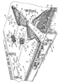
- reference numeral 1 denotes existing untouched ground, respectively where original mass has been substituted by more appropriate mass.
- the football field Prior to the work by which the football field is built up from below and upwardly of a plurality of layers included in the pitch body/the heating plant therefore, it may, according to the invention, be suitable to build an elongate culvert K extending in the longitudinal direction of the resultant football field, and the upper, outer roof surface KT of the culvert may be positioned at substantially the same level as the upper surface of the mass layer 1.
- a draining layer 2 follows, which is rounded off quite accurately in respect of the desired slope. Thereafter, an insulation layer 3 is laid.
- the heat energy distributing system of the plant which, in accordance with the present embodyment form, comprises two substantially horizontal cavity layers which, apart from a larger number of holes 5' in a corrugated plate layer 5 along the outer edges of the pitch body, are separated from each other, causing heated air supplied thereto to be distributed approximately regularly across the area of the total pitch in the lower cavity layer, heating up adjacent mass, material, etc., before the heating air, in a somewhat cooler condition, leaves the lower cavity layer and, through the holes 5', flows up into the upper cavity layer of the heating device, from where the cooler, gaseous energy carrier is sucked out, preferably, for reheating and utilization of the rest heat thereof.
- a plurality of air suction and air discharge devices are disposed equidistantly across the field area.
- the two parallel cavity layers which, apart from local fluid communication through the vertically through-going air transferring holes 5' along the outer edges of the pitch, shall be separated from each other for the purpose of distributing supplied heated air across, preferably, the whole area of a lower cavity layer, are formed by means of three corrugated plate layers 4, 5 and 6, of which the lowermost and uppermost corrugated plate layer 4 and 6 with their rectilinear crests of waves can extend in the longitudinal direction of the resulting grass field, while the intermediate corrugated plate layer 5 with the holes 5' is orientated perpendicularly to the rectilinear crests of waves of the remaining corrugated plate layers 4, 6. Construction of the underground, air-based heating plant by means of corrugated plates of steel which are joined together to form large flake-like layers results, upon the choice of a moderate plate thickness dimension, in a very strong and load resistant structure.
- a concrete layer 7 is cast, constituting a permanent, horizontal support layer securing the evenness of overlying layers 8-10, of which 8 denotes a draining mass layer, 9 a so-called building cloth and 10 the growing or cultivation layer (turf layer).
- these draining pipes 11 are multifunctional pipes and can be used for venting or watering, respectively (internally within the pitch-body), as this draining pipe system in the first case is coupled to an air injection aggregate or several such aggregates respectively, in the latter case is coupled to water supply aggregates for internal watering of the pitch body.
- a gardener's felt 12 is disposed, as previously explained.
- one or more aggregates 13 for generating/heating hot air are built in, said hot air being passed into a longitudinal pipe 14 exhibiting lateral branch pipes 15 which, regularly distributed across the field area, have upright, angled, upwardly open pipe pieces 15' assigned blow out places 16 for supply air, respectively exhaust places 17 for suction of return air.
- a grass field built up in accordance with the invention functions such in combination with the air-based heating system 4,5,6,13,14,15,16,17 that heated gaseous energy carrier from the aggregate 13 through the pipes 14, 15, 15' ends in the lowermost cavity layer and distributes itself within the same before the air subsequently to heat loss leaves the lower cavity layer through the edge holes 5' of the intermediate corrugated plate layer 5 and lands in an up-permost cavity layer, in which prevails a vacuum or suction effect, established by means of an air transport fan (not shown) which may be included in the aggregate 13. Used air is sucked from the uppermost cavity layer through the exhaust place 17, and this, somewhat cooled air is utilized in respect of its possible rest heat and is, therefore, heated again within the aggregate 13.
- the uppermost corrugated plate 6 is in contact with the concrete layer 7 and, heat transferringly, also with the remaining overlying layers, the draining masse layer 8 and the uppermost growing or cultivation layer 10 with the intermediate building cloth 9.
- the difference between the temperature of the energy-containing air in contact with the uppermost corrugated plate 6 and the temperature of overlying layers causes a temperature equalizing effect to take place, drawing off heat energy from the energy-containing air.
- an efficient heat exchange is achieved at a minimum of energy consumption. If desired, cold air may, of course, be supplied through the aggregate 13.
- the pipes 11 of the combined pipe system for draining, venting and internal watering is, from a longitudinal centre line, placed in a herring bone pattern.
- the pipes 11 are ordinarily available draining pipes which, however, have been laid slopingly of the order 1:200 out towards the goal lines; slopes of approximately 1:100 being usual in ordinary football grounds.
- the draining/venting/watering pipes 11 are laid immediately on top of the concrete layer 7.
- a flat, practically level pitch cover 10 represents considerable advantages in relation to conventional pitch covers of football grounds in which the slope to opposite sides is substantial from the centre of the pitch.
- the positioning of the building cloth 9 and the gardener's felt 12 is advantageous. Subsequently to a considerable rain weather, a so-called cloudburst, this cloth 9 and this felt 12 will be completely soaked and represent an advantageous reserve water source at the right place for optimal growth-favouring for the grass plants in periods with less rain.
- draining pipe system 11 Upon the utilization of the draining pipe system 11 as underground watering system, one may, periodically, use water, possibly liquid manure, which is pumped into the pipe system 11 in a way not closer shown.
- the draining pipe system 11 is everywhere provided with intermediate, partially open slots or through-going perforations, respectively, and some of the, possibly manured, watering water supplied thereto has, thus, the possibility of seeping.out through the openings to the dry, moisture-absorbing gardener's felt 12 which, thus, acts as a wick, transferring water to the overlying building cloth 9.
- This water transfer from the draining pipe system 11 to the building cloth 9 immediately beneath the growth/cultivating layer 10 causes an even water distribution across the entire pitch area. The result is an efficient watering of the grass roots from below.
- the draining pipe system can be coupled to an air compressor or pumping device which provides injection of air in order to vent the pitch cover. Air escapes little by little through the perforations of the pipe system 11, flowing out into the mass layer 8, from there through the gardener's felt layer 12 and the building cloth 9, before it flows up through the growth layer 10 and out into the free atmosphere. On its way up through the growth layer 10, free oxygen is supplied to the root system of the grass plants. Venting of the growth layer 10 may well take place simultaneously with watering by means of the draining pipe system.
- an overpressure in the pipes 11 arising in connection with venting causes the displacement of watering water efficiently out from the pipes 11, so that it first comes into contact with the gardener's felt 12, thereafter with the "working cloth” 9 and then with the grass roots in the growth layer 10 such as previously described.
Landscapes
- Engineering & Computer Science (AREA)
- Architecture (AREA)
- Civil Engineering (AREA)
- Structural Engineering (AREA)
- Road Paving Structures (AREA)
- Cultivation Of Plants (AREA)
- Road Repair (AREA)
- Inorganic Fibers (AREA)
- Resistance Heating (AREA)
- Paper (AREA)
- Yarns And Mechanical Finishing Of Yarns Or Ropes (AREA)
- Insulating Bodies (AREA)
Claims (9)
- Verfahren zum Herstellen einer Schichtkonstruktion eines Grasspielfelds, beispielsweise eines Fußballfelds, umfassend ein Grasfeld in der Form einer ganz oben angeordneten Wachstumsschicht (10) und darunter liegenden Schichten (1, 8), die eine Drainagemassenschicht (2) enthalten, die ein Drainagerohrsystem (11) einschließt, das Grasspielfeld hat eine Untergrundanlage (4 - 6, 13 - 17) angeordnet, um thermische Energie unter Verwendung eines gasförmigen Energieträgers wie beispielsweise Luft zu versorgen, dadurch gekennzeichnet, dass auf der Oberseite der Massenschicht (1) die Drainagemassenschicht (2) und eine Isolationsschicht (3) angeordnet sind und auf der Oberseite der Isolationsschicht (3) mindestens zwei im wesentlichen horizontale Höhlungsschichten (4, 6) gebildet sind, die durch eine zwischenliegende Trennungsschicht (5) getrennt sind, die lokal angeordnete Fluidverbindungslöcher (5') hat, die Höhlungsschichten (4, 6) erstrecken sich im wesentlichen über den gesamten Bereich des Feldes, und bei dem die untere Höhlungsschicht (4) vorgesehen ist, um eine Versorgung mit Luft aufzunehmen, während die obere Höhlungsschicht (6) vorgesehen ist, Rückluft an eine Sauggebläsevorrichtung o. ä. zu geben, und dass auf der Oberseite einer horizontal angeordneten oberen Plattenschicht (6), die die obere Höhlungsschicht (6) definiert, eine Schicht (7) aus Beton oder anderen tragenden gießbaren Materialen gegossen ist, auf deren Oberseite das Drainagerohrsystem (11) angeordnet ist, die Wachstumsschicht (10) ist die letzte, die verlegt wird.
- Verfahren nach Anspruch 1, dadurch gekennzeichnet, dass auf der Oberseite des Drainagerohrsystems (11) zusätzliche, anfeuchtbare Absorptionsschichten (8, 9) verlegt sind, die eine Rückzugswasserquelle für die Wachstumsschicht (10) in Trockenperioden bilden.
- Verfahren nach Anspruch 1 oder 2, dadurch gekennzeichnet, dass das Drainagerohrsystem (11) mit einer Wasserversorgungsvorrichtung und/oder einer Versorgungsluftblasvorrichtung verbunden ist, um das Drainagerohrsystem (11) in ein Bewässerungs- und/oder Ventilationssystem umzuwandeln.
- Verfahren nach Anspruch 1, dadurch gekennzeichnet, dass die zwischenliegende Trennungsschicht (5) so angeordnet ist, dass die Verbindungslöcher (5') sich vertikal dadurch erstrecken und an oder in der Nähe zu einer oder mehreren durch das Grasspielfeld gebildeten Grenzen angeordnet sind.
- Verfahren nach Anspruch 1 oder 4, dadurch gekennzeichnet, dass die zwei horizontalen Höhlungsschichten (4, 6) sich im wesentlichen über den Bereich des Grasspielfelds erstrecken und in Fluidverbindung miteinander nur durch die Verbindungslöcher (5') der Trennungsschicht (5) sind, die untere Höhlungsschicht (4) ist definiert zwischen einer unteren gewellten Platte (4), die sich in eine erste Richtung erstreckende geradlinige Wellenkämme hat, und die Trennungsschicht (5) bildet auf ähnliche Weise eine weitere gewellte Plattenschicht mit geradlinigen Wellenkämmen, die sich in eine zweite Richtung, die senkrecht zu der ersten Richtung ist, erstrecken, und dass die obere Höhlungsschicht (6) zwischen der Trennungsschicht (5) und einer oberen gewellten Plattenschicht (6), deren geradlinige Wellenkämme sich parallel zu denen der unteren gewellten Plattenschicht (4) erstrecken, definiert wird.
- Ein Grasspielfeld, insbesondere eine Fußballspielfeld, umfassend eine ganz oben positionierte Wachstumsschicht (10), und darunter liegende Schichten (1, 8), die ein Drainagerohrsystem (11) mit einer Drainagemassenschicht (2) enthalten, das Grasspielfeld schließt eine Untergrundanlage (4 - 6, 13 - 17) ein, die ausgebildet zum Versorgen mit thermischer Energie ist, dadurch gekennzeichnet, dass das Grasspielfeld umfasst auf seiner Unterseite eine Massenschicht (1), über der eine Drainagemassenschicht (2), gefolgt von einer Isolationsschicht (3), angeordnet ist, auf deren Oberseite mindestens zwei im wesentlichen horizontale Höhlungsschichten (4, 6) angeordnet sind, die durch eine zwischenliegende Trennungsschicht (5), die lokal angeordnete Fluidverbindungslöcher (5') hat, angeordnet sind, die Höhlungsschichten (4, 6) erstrecken sich im wesentlichen über den gesamten Bereich des Felds, und bei dem die untere Höhlungsschicht (4) angeordnet ist, um eine Versorgung mit Luft aufzunehmen, während die obere Höhlungsschicht (6) angeordnet ist, um Rückluft an eine Sauggebläsevorrichtung o. ä. zurückzugeben, und dass auf der Oberseite einer horizontal angeordneten oberen Plattenschicht (6), welche die obere Höhlungsschicht (6) definiert, eine Schicht (7) aus Beton oder anderen lastragenden gießbaren Materialien angeordnet ist, wobei das Drainagerohrsystem (11) über der Schicht (7) aus Beton installiert ist und die bekannte Wachstumsschicht (10) immer noch über dem Drainagerohrsystem (11) ist.
- Ein Grasspielfeld nach Anspruch 6, dadurch gekennzeichnet, dass zwischen der obersten Wachstumsschicht (10) und der Betonschicht (7) Lagen von feuchtigkeitsabsorbierenden/-abgebenden Materialen wie beispielsweise einem Gärtnerfilz (12) und einem Bautuch (9) angeordnet sind.
- Grasspielfeld nach Anspruch 6, dadurch gekennzeichnet, dass über der Massenschicht (1) drei horizontal, parallel gewellte Plattenschichten (4 - 6) vorgesehen sind, die zwischen sich selbst die zwei Höhlungsschichten (4, 6) bilden, die Höhlungen der Höhlungsschichten (4, 6) sind geeignet zum Verteilen von warmer Luft, wobei vorzugsweise die unterste Höhlungsschicht eine Versorgung mit erhitzter Versorgungsluft hat, und die oberste Höhlungsschicht mit einer Sauggebläsevorrichtung verbunden ist.
- Grasspielfeld nach Anspruch 6, dadurch gekennzeichnet, dass ein Lufteinbringungsaggregat (13) mit dem Drainagerohrsystem (11) verbunden ist, wobei das Lufteinbringungsaggregat (13) ausgebildet ist, um eine Luftversorgung in das Drainagerohrsystem (11) bereitzustellen in Perioden, in denen Bedarf für Ventilation besteht.
Applications Claiming Priority (3)
| Application Number | Priority Date | Filing Date | Title |
|---|---|---|---|
| NO973111 | 1997-07-04 | ||
| NO973111A NO973111A (no) | 1997-07-04 | 1997-07-04 | Fremgangsmåte for lagvis oppbygging og oppvarming av gressbane, særlig fotballbane, og gressbane bygget opp i overensstemmelse med fremgangsmåten |
| PCT/NO1998/000163 WO1999001619A1 (en) | 1997-07-04 | 1998-06-04 | A method for stratified construction and heating a grass pitch, particularly a football ground, and a grass playing field built up in accordance with the method |
Publications (2)
| Publication Number | Publication Date |
|---|---|
| EP1007790A1 EP1007790A1 (de) | 2000-06-14 |
| EP1007790B1 true EP1007790B1 (de) | 2004-10-20 |
Family
ID=19900897
Family Applications (1)
| Application Number | Title | Priority Date | Filing Date |
|---|---|---|---|
| EP98939024A Expired - Lifetime EP1007790B1 (de) | 1997-07-04 | 1998-06-04 | Verfahren für einen schichtförmigen Aufbau und Beheizung eines Grasspielfeldes, insbesondere eines Fussballfeldes, sowie derartige hergestelltes Grassspielfeld |
Country Status (11)
| Country | Link |
|---|---|
| US (1) | US6398455B1 (de) |
| EP (1) | EP1007790B1 (de) |
| JP (1) | JP2002508818A (de) |
| KR (1) | KR20010020553A (de) |
| CN (1) | CN1123665C (de) |
| AT (1) | ATE280274T1 (de) |
| AU (1) | AU732826B2 (de) |
| CA (1) | CA2294231C (de) |
| DE (1) | DE69827146T2 (de) |
| NO (1) | NO973111A (de) |
| WO (1) | WO1999001619A1 (de) |
Cited By (1)
| Publication number | Priority date | Publication date | Assignee | Title |
|---|---|---|---|---|
| GB2644285A (en) * | 2024-09-25 | 2026-04-01 | Water Products Ltd | Sports surface |
Families Citing this family (24)
| Publication number | Priority date | Publication date | Assignee | Title |
|---|---|---|---|---|
| NO307142B1 (no) | 1998-06-02 | 2000-02-14 | Voelstad Energy As | Stadionanlegg med arena så som en isbane, og omkringliggende tribune for publikum, samt kanalelement for kanalsystem i stadionanlegg så som en isbane, og omkringliggende tribune for publikum |
| NO317828B1 (no) * | 1998-06-02 | 2004-12-13 | Volstad Energy As | Anordning ved konstruksjonselement som inngar i en bygnings- eller anlegggskonstruksjon, og som er utformet slik at den omfatter et kanalsystem for luft |
| US6698141B2 (en) * | 2001-01-23 | 2004-03-02 | Uni-Systems, Llc | Convertible stadium and method of operating |
| US7338431B2 (en) * | 2001-04-03 | 2008-03-04 | Baugh Carl E | Method and apparatus to stimulate the immune system of a biological entity |
| US6902521B2 (en) * | 2001-04-03 | 2005-06-07 | Carl E. Baugh | System and method to enhance growth and biological function of living systems with pulsed electromagnetic energy |
| CA2377702C (en) * | 2002-03-20 | 2004-03-16 | Diamond J Industries Ltd. | A method of reducing ground disturbance during freeze-thaw cycles and a subsurface insulation material |
| BR0314653B1 (pt) * | 2002-09-30 | 2014-06-10 | Aquatan Pty Ltd | "barreira geotécnica e respectivo método de construção e operação". |
| US7108454B2 (en) * | 2004-10-12 | 2006-09-19 | Airfield Systems, L.L.C. | Subsurface drainage system and drain structure therefor |
| FR2877535B1 (fr) * | 2004-10-28 | 2006-12-22 | Fernand Scherrer | Dispositif de chauffage de sols, notamment recouverts d'un revetement de synthese |
| US8399027B2 (en) | 2005-04-14 | 2013-03-19 | 3M Innovative Properties Company | Silver coatings and methods of manufacture |
| US20070166399A1 (en) | 2006-01-13 | 2007-07-19 | 3M Innovative Properties Company | Silver-containing antimicrobial articles and methods of manufacture |
| US20080098652A1 (en) * | 2006-10-30 | 2008-05-01 | Kenneth Thomas Weinbel | Sport playing field |
| US7815395B1 (en) * | 2009-04-08 | 2010-10-19 | Airfield Systems, L.L.C | Subsurface drainage system and drain structure therefor |
| RU2475584C2 (ru) * | 2010-06-09 | 2013-02-20 | Сергей Михайлович Рачкин | Способ создания и обслуживания спортивного газона и спортивный газон |
| US8882441B2 (en) | 2010-07-07 | 2014-11-11 | ATOPIA Research | Deployable wind power and battery unit |
| US20130333860A1 (en) * | 2011-02-17 | 2013-12-19 | Soletanche Freyssinet | Structural element for transitory storage and deferred use of thermal energy, related structure and methods |
| US9120004B2 (en) * | 2011-06-30 | 2015-09-01 | Nutcracker Solutions As | Sports stadium with removable turf field |
| NL2015543B1 (en) * | 2015-10-02 | 2017-04-21 | Ten Cate Thiolon Bv | Artificial turf system with forced airflow. |
| FR3044696A1 (fr) * | 2015-12-08 | 2017-06-09 | Francois Henri Cathala | Terrain de sport d'un complexe sportif pour la gestion de pratiques sportives et l'installation d'unites de production d'energie |
| US10577755B1 (en) * | 2017-08-16 | 2020-03-03 | Subair Systems Llc | Wireless sensor-based turf heating and cooling |
| US10975534B1 (en) | 2017-08-16 | 2021-04-13 | Subair Systems Llc | Wireless sensor-based turf heating and cooling |
| CN109006043A (zh) * | 2018-06-20 | 2018-12-18 | 内蒙古蒙草生态环境(集团)股份有限公司 | 一种因地制宜的足球场草坪坪床结构及其构建方法 |
| CN110332712B (zh) * | 2019-07-05 | 2021-01-05 | 大连民族大学 | 高尔夫球场泡池供热及草坪加温系统 |
| EP4278043A4 (de) * | 2021-01-18 | 2024-11-27 | Technology Licensing Corp. | Wurzelzonenerwärmungssystem für sportfeld mit natürlichem rasen |
Family Cites Families (14)
| Publication number | Priority date | Publication date | Assignee | Title |
|---|---|---|---|---|
| US1050914A (en) * | 1912-03-25 | 1913-01-21 | Arthur M Branch | Ground-drying-out system. |
| US3908385A (en) | 1972-06-16 | 1975-09-30 | Purdue Research Foundation | Planted surface conditioning system |
| US4023506A (en) * | 1976-03-08 | 1977-05-17 | Purdue Research Foundation | System and process for providing durability enhanced area |
| US4268993A (en) * | 1979-05-18 | 1981-05-26 | Cunningham Percy C | Grass sports surfaces and a method for maintaining them |
| US4462184A (en) * | 1979-05-18 | 1984-07-31 | Cunningham Percy C | System for improving synthetic surfaces |
| US4832526A (en) * | 1987-11-27 | 1989-05-23 | Har-Tru Corporation | Underground watering system |
| WO1989012719A1 (en) * | 1988-06-20 | 1989-12-28 | A. Husu Ky | A field construction for a sports or other field |
| US4913596A (en) * | 1989-05-04 | 1990-04-03 | Erosion Control Systems, Inc. | Athletic field construction |
| US5120158A (en) | 1989-06-16 | 1992-06-09 | Aarne Husu | Apparatus and method for heating a playfield |
| SE500700C2 (sv) | 1991-07-08 | 1994-08-15 | Profu Ab | Separationsskikt för anläggning av gräsytor på sand- och/eller grusunderlag samt användning av separationsskiktet |
| US5254039A (en) * | 1992-09-10 | 1993-10-19 | Juan Garcia | Playground construction |
| US5752784A (en) * | 1995-02-17 | 1998-05-19 | The Motz Group | Low profile drainage network for athletic field drainage system |
| US5746028A (en) * | 1997-06-26 | 1998-05-05 | Dibenedetto; John | Moveable grass field |
| US5944444A (en) * | 1997-08-11 | 1999-08-31 | Technology Licensing Corp. | Control system for draining, irrigating and heating an athletic field |
-
1997
- 1997-07-04 NO NO973111A patent/NO973111A/no not_active IP Right Cessation
-
1998
- 1998-06-04 US US09/445,882 patent/US6398455B1/en not_active Expired - Fee Related
- 1998-06-04 EP EP98939024A patent/EP1007790B1/de not_active Expired - Lifetime
- 1998-06-04 AU AU87533/98A patent/AU732826B2/en not_active Ceased
- 1998-06-04 KR KR1019997012408A patent/KR20010020553A/ko not_active Ceased
- 1998-06-04 WO PCT/NO1998/000163 patent/WO1999001619A1/en not_active Ceased
- 1998-06-04 AT AT98939024T patent/ATE280274T1/de not_active IP Right Cessation
- 1998-06-04 DE DE69827146T patent/DE69827146T2/de not_active Expired - Fee Related
- 1998-06-04 JP JP50696999A patent/JP2002508818A/ja active Pending
- 1998-06-04 CN CN98806816A patent/CN1123665C/zh not_active Expired - Fee Related
- 1998-06-04 CA CA002294231A patent/CA2294231C/en not_active Expired - Fee Related
Cited By (1)
| Publication number | Priority date | Publication date | Assignee | Title |
|---|---|---|---|---|
| GB2644285A (en) * | 2024-09-25 | 2026-04-01 | Water Products Ltd | Sports surface |
Also Published As
| Publication number | Publication date |
|---|---|
| JP2002508818A (ja) | 2002-03-19 |
| CA2294231A1 (en) | 1999-01-14 |
| NO973111D0 (no) | 1997-07-04 |
| CA2294231C (en) | 2009-04-07 |
| AU732826B2 (en) | 2001-05-03 |
| US6398455B1 (en) | 2002-06-04 |
| CN1261939A (zh) | 2000-08-02 |
| WO1999001619A1 (en) | 1999-01-14 |
| CN1123665C (zh) | 2003-10-08 |
| ATE280274T1 (de) | 2004-11-15 |
| EP1007790A1 (de) | 2000-06-14 |
| AU8753398A (en) | 1999-01-25 |
| NO304415B1 (no) | 1998-12-14 |
| NO973111A (no) | 1998-12-14 |
| DE69827146D1 (de) | 2004-11-25 |
| KR20010020553A (ko) | 2001-03-15 |
| DE69827146T2 (de) | 2006-03-09 |
Similar Documents
| Publication | Publication Date | Title |
|---|---|---|
| EP1007790B1 (de) | Verfahren für einen schichtförmigen Aufbau und Beheizung eines Grasspielfeldes, insbesondere eines Fussballfeldes, sowie derartige hergestelltes Grassspielfeld | |
| RU2293815C2 (ru) | Искусственная поверхность со встроенным терморегулированием | |
| AU2002328220A1 (en) | Artificial surface with integrated thermal regulation | |
| CN101828488B (zh) | 一种楼房生态绿化系统 | |
| JP2014511151A (ja) | 芝用格子 | |
| CN111587697A (zh) | 一种北方地区智能屋顶花园系统及施工方法 | |
| KR100426321B1 (ko) | 옥상 퍼팅 그린 및 그 시공방법 | |
| CN107257874B (zh) | 表面的灌溉、排放和/或加热系统以及用于加热表面的方法 | |
| WO2020230430A1 (ja) | 半地下式農業用ハウス | |
| CN1676812A (zh) | 坡面屋顶草坪 | |
| KR19980082050A (ko) | 태양열 복합 냉,난방 강제 흡,호기 순환식 잔디경기장 잔디관리시스템 | |
| GB2288306A (en) | Modular sports field construction | |
| JP2002364130A (ja) | 軽量保水性断熱屋根 | |
| RU2475584C2 (ru) | Способ создания и обслуживания спортивного газона и спортивный газон | |
| RU2118080C1 (ru) | Устройство для обогрева спортивного газона | |
| KR101182057B1 (ko) | 갈대 식재를 통한 옥상 바닥 마감 공법 | |
| JP2018019660A (ja) | 熱交換システム | |
| CN114916419A (zh) | 荒漠地区蒸汽灌溉装置及种植方法 | |
| Maguire | The use of soil warming to protect sports fixtures | |
| RU2041608C1 (ru) | Гряда для выращивания растений | |
| CN116076351A (zh) | 一种日光温室蔬菜栽培用灌溉装置 | |
| JP2004137741A (ja) | 緑化を特徴としたダブルルーフ | |
| JP2007006798A (ja) | 屋上緑化システム | |
| JPH08149923A (ja) | 緑化システム | |
| JPH05153870A (ja) | 構造物の屋上加温装置 |
Legal Events
| Date | Code | Title | Description |
|---|---|---|---|
| PUAI | Public reference made under article 153(3) epc to a published international application that has entered the european phase |
Free format text: ORIGINAL CODE: 0009012 |
|
| 17P | Request for examination filed |
Effective date: 20000125 |
|
| AK | Designated contracting states |
Kind code of ref document: A1 Designated state(s): AT BE CH DE DK ES FI FR GB GR IE IT LI NL PT SE |
|
| 17Q | First examination report despatched |
Effective date: 20030305 |
|
| GRAP | Despatch of communication of intention to grant a patent |
Free format text: ORIGINAL CODE: EPIDOSNIGR1 |
|
| RTI1 | Title (correction) |
Free format text: AMETHOD FOR STRATIFIED CONSTRUCTION AND HEATING A GRASS PITCH, PARTICULARLY A FOOTBALL GROUND, AND A GRASS PLAYING FIELD |
|
| GRAS | Grant fee paid |
Free format text: ORIGINAL CODE: EPIDOSNIGR3 |
|
| GRAA | (expected) grant |
Free format text: ORIGINAL CODE: 0009210 |
|
| AK | Designated contracting states |
Kind code of ref document: B1 Designated state(s): AT BE CH DE DK ES FI FR GB GR IE IT LI NL PT SE |
|
| PG25 | Lapsed in a contracting state [announced via postgrant information from national office to epo] |
Ref country code: NL Free format text: LAPSE BECAUSE OF FAILURE TO SUBMIT A TRANSLATION OF THE DESCRIPTION OR TO PAY THE FEE WITHIN THE PRESCRIBED TIME-LIMIT Effective date: 20041020 Ref country code: LI Free format text: LAPSE BECAUSE OF FAILURE TO SUBMIT A TRANSLATION OF THE DESCRIPTION OR TO PAY THE FEE WITHIN THE PRESCRIBED TIME-LIMIT Effective date: 20041020 Ref country code: IT Free format text: LAPSE BECAUSE OF FAILURE TO SUBMIT A TRANSLATION OF THE DESCRIPTION OR TO PAY THE FEE WITHIN THE PRESCRIBED TIME-LIMIT;WARNING: LAPSES OF ITALIAN PATENTS WITH EFFECTIVE DATE BEFORE 2007 MAY HAVE OCCURRED AT ANY TIME BEFORE 2007. THE CORRECT EFFECTIVE DATE MAY BE DIFFERENT FROM THE ONE RECORDED. Effective date: 20041020 Ref country code: FR Free format text: LAPSE BECAUSE OF FAILURE TO SUBMIT A TRANSLATION OF THE DESCRIPTION OR TO PAY THE FEE WITHIN THE PRESCRIBED TIME-LIMIT Effective date: 20041020 Ref country code: FI Free format text: LAPSE BECAUSE OF FAILURE TO SUBMIT A TRANSLATION OF THE DESCRIPTION OR TO PAY THE FEE WITHIN THE PRESCRIBED TIME-LIMIT Effective date: 20041020 Ref country code: CH Free format text: LAPSE BECAUSE OF FAILURE TO SUBMIT A TRANSLATION OF THE DESCRIPTION OR TO PAY THE FEE WITHIN THE PRESCRIBED TIME-LIMIT Effective date: 20041020 Ref country code: BE Free format text: LAPSE BECAUSE OF FAILURE TO SUBMIT A TRANSLATION OF THE DESCRIPTION OR TO PAY THE FEE WITHIN THE PRESCRIBED TIME-LIMIT Effective date: 20041020 Ref country code: AT Free format text: LAPSE BECAUSE OF FAILURE TO SUBMIT A TRANSLATION OF THE DESCRIPTION OR TO PAY THE FEE WITHIN THE PRESCRIBED TIME-LIMIT Effective date: 20041020 |
|
| REG | Reference to a national code |
Ref country code: GB Ref legal event code: FG4D |
|
| REG | Reference to a national code |
Ref country code: CH Ref legal event code: EP |
|
| REG | Reference to a national code |
Ref country code: IE Ref legal event code: FG4D |
|
| REF | Corresponds to: |
Ref document number: 69827146 Country of ref document: DE Date of ref document: 20041125 Kind code of ref document: P |
|
| PG25 | Lapsed in a contracting state [announced via postgrant information from national office to epo] |
Ref country code: SE Free format text: LAPSE BECAUSE OF FAILURE TO SUBMIT A TRANSLATION OF THE DESCRIPTION OR TO PAY THE FEE WITHIN THE PRESCRIBED TIME-LIMIT Effective date: 20050120 Ref country code: GR Free format text: LAPSE BECAUSE OF FAILURE TO SUBMIT A TRANSLATION OF THE DESCRIPTION OR TO PAY THE FEE WITHIN THE PRESCRIBED TIME-LIMIT Effective date: 20050120 Ref country code: DK Free format text: LAPSE BECAUSE OF FAILURE TO SUBMIT A TRANSLATION OF THE DESCRIPTION OR TO PAY THE FEE WITHIN THE PRESCRIBED TIME-LIMIT Effective date: 20050120 |
|
| PG25 | Lapsed in a contracting state [announced via postgrant information from national office to epo] |
Ref country code: ES Free format text: LAPSE BECAUSE OF FAILURE TO SUBMIT A TRANSLATION OF THE DESCRIPTION OR TO PAY THE FEE WITHIN THE PRESCRIBED TIME-LIMIT Effective date: 20050131 |
|
| REG | Reference to a national code |
Ref country code: CH Ref legal event code: PL |
|
| NLV1 | Nl: lapsed or annulled due to failure to fulfill the requirements of art. 29p and 29m of the patents act | ||
| PG25 | Lapsed in a contracting state [announced via postgrant information from national office to epo] |
Ref country code: IE Free format text: LAPSE BECAUSE OF NON-PAYMENT OF DUE FEES Effective date: 20050606 |
|
| PLBE | No opposition filed within time limit |
Free format text: ORIGINAL CODE: 0009261 |
|
| STAA | Information on the status of an ep patent application or granted ep patent |
Free format text: STATUS: NO OPPOSITION FILED WITHIN TIME LIMIT |
|
| 26N | No opposition filed |
Effective date: 20050721 |
|
| EN | Fr: translation not filed | ||
| REG | Reference to a national code |
Ref country code: IE Ref legal event code: MM4A |
|
| PG25 | Lapsed in a contracting state [announced via postgrant information from national office to epo] |
Ref country code: PT Free format text: LAPSE BECAUSE OF NON-PAYMENT OF DUE FEES Effective date: 20050320 |
|
| PGFP | Annual fee paid to national office [announced via postgrant information from national office to epo] |
Ref country code: DE Payment date: 20080807 Year of fee payment: 11 |
|
| PGFP | Annual fee paid to national office [announced via postgrant information from national office to epo] |
Ref country code: GB Payment date: 20080606 Year of fee payment: 11 |
|
| GBPC | Gb: european patent ceased through non-payment of renewal fee |
Effective date: 20090604 |
|
| PG25 | Lapsed in a contracting state [announced via postgrant information from national office to epo] |
Ref country code: GB Free format text: LAPSE BECAUSE OF NON-PAYMENT OF DUE FEES Effective date: 20090604 |
|
| PG25 | Lapsed in a contracting state [announced via postgrant information from national office to epo] |
Ref country code: DE Free format text: LAPSE BECAUSE OF NON-PAYMENT OF DUE FEES Effective date: 20100101 |