EP1007796B1 - Verbesserungen bezüglich einer unterwasserbaggervorrichtung - Google Patents
Verbesserungen bezüglich einer unterwasserbaggervorrichtung Download PDFInfo
- Publication number
- EP1007796B1 EP1007796B1 EP96942501A EP96942501A EP1007796B1 EP 1007796 B1 EP1007796 B1 EP 1007796B1 EP 96942501 A EP96942501 A EP 96942501A EP 96942501 A EP96942501 A EP 96942501A EP 1007796 B1 EP1007796 B1 EP 1007796B1
- Authority
- EP
- European Patent Office
- Prior art keywords
- excavation apparatus
- underwater excavation
- rotor
- stator
- inlets
- Prior art date
- Legal status (The legal status is an assumption and is not a legal conclusion. Google has not performed a legal analysis and makes no representation as to the accuracy of the status listed.)
- Expired - Lifetime
Links
Images




Classifications
-
- E—FIXED CONSTRUCTIONS
- E02—HYDRAULIC ENGINEERING; FOUNDATIONS; SOIL SHIFTING
- E02F—DREDGING; SOIL-SHIFTING
- E02F5/00—Dredgers or soil-shifting machines for special purposes
- E02F5/28—Dredgers or soil-shifting machines for special purposes for cleaning watercourses or other ways
-
- E—FIXED CONSTRUCTIONS
- E02—HYDRAULIC ENGINEERING; FOUNDATIONS; SOIL SHIFTING
- E02F—DREDGING; SOIL-SHIFTING
- E02F5/00—Dredgers or soil-shifting machines for special purposes
- E02F5/28—Dredgers or soil-shifting machines for special purposes for cleaning watercourses or other ways
- E02F5/287—Dredgers or soil-shifting machines for special purposes for cleaning watercourses or other ways with jet nozzles
Definitions
- This invention relates to an improved excavation apparatus, and in particular to an improved underwater excavation apparatus.
- Underwater excavation apparatus are known, eg, from GB 2 240 568 (CONSORTIUM RESOURCE et al).
- an underwater excavation apparatus comprising a hollow body with an inlet to receive water and an outlet for discharge of water.
- a propeller is rotatably mounted in the hollow body to draw water through the inlet and deliver a flow of water through the outlet. Water jets on the propeller tips rotate the propeller when water is supplied to the jets.
- Such rotation causes water to be drawn into the body through the inlet and expelled from the body as a flow through the outlet.
- the flow can be used to displace material on the seabed.
- an underwater excavation apparatus comprising a hollow body having at least one inlet and at least one outlet, at least one pair of impellers rotatably mounted in the hollow body and means for driving the impellers.
- the driving means cause the impellers to be driven in contrary rotating directions, in use.
- the at least one inlet may be inclined at an angle to an axis along which the at least one outlet is provided.
- At least one pair of inlets there is provided at least one pair of inlets.
- the at least one pair of inlets are substantially symmetrically disposed around an axis extending from the outlet.
- the underwater excavation apparatus comprises a pair of horizontally opposed inlets communicating with a single outlet, the outlet being disposed vertically downwards substantially midway between the two inlets, in use.
- the excavation apparatus is, therefore, substantially "T" shaped in profile.
- the underwater excavation apparatus comprises a pair of inlets communicating with a single outlet, the inlets being substantially symmetrically disposed around an axis extending from the outlet, the outlet being disposed vertically downwards substantially midway between the two inlets, in use.
- the excavation apparatus is, therefore, substantially "Y" shaped in profile.
- the outlets are each spaced/inclined substantially 45° from the axis extending from the outlet.
- At least one impeller may be provided within/adjacent each inlet.
- the means for driving the/each impeller(s) may include at least one drilling motor.
- the at least one drilling motor may comprise a stator and a rotor rotatably mounted in the stator, the stator being provided with a rod recess and an exhaust port, the rotor being provided with a rotor channel and at least one channel for conducting motive fluid from the rotor channel to a chamber between the rotor and the stator, the rod recess being provided with a rod which, in use, forms a seal between the stator and the rotor.
- the rotor be provided with a seal for engagement with the stator.
- the seal is made from a material selected from the group consisting of plastics materials, polyethylethylketone, metal, copper alloys and stainless steel.
- the rod is made from a material selected from the group consisting of plastics materials, polyethylethylketone, metal, copper alloys and stainless steel.
- the stator is provided with two rod recesses which are disposed opposite one another, and two exhaust ports which are disposed opposite one another, each of the rod recesses being provided with a respective rod, the rotor having two seals which are disposed opposite one another.
- the drilling motor may advantageously comprise two drilling motors arranged with their respective rotors connected together each motor comprising a stator and a rotor rotatably mounted in the stator, the stator being provided with a rod recess and an exhaust port, the rotor being provided with a rotor channel and at least one channel for conducting motive fluid from the rotor channel to a chamber between the rotor and the stator, the rod recess being provided with a rod which, in use, forms a seal between the stator and the rotor.
- the drilling motors are connected in parallel, although they could be connected in series if desired.
- the drilling motors are arranged so that, in use, one drilling motor operates out of phase with the other.
- each drilling motor has two chambers and the chambers in the first drilling motor are 90° out of phase with the chambers in the second drilling motor.
- the chambers in the first drilling motor would preferably be 45° out of phase with the chambers on the second drilling motor. This arrangement helps ensure a smooth power output and inhibits stalling.
- the at least one drilling motor may be a "Moineau", hydraulic or a suitably adapted electric motor.
- the impellers may be driven by means of a gearbox or by exploitation of the opposing reactive torque on a drive body of the motor.
- At least one impeller may be connected to an output shaft of said motor, while at least one other impeller may be connected to the motor body.
- impellers may be driven by a pair of motors operating in opposite directions. In such case said motors and impellers are balanced and equal.
- the underwater excavation apparatus may further comprise an agitator device having mechanical disturbance means and fluid flow disturbance means.
- the underwater excavation apparatus may, in use, be suspended from a surface vessel or mounted upon a sled of the type currently known for use in subsea excavation operations.
- an underwater apparatus comprising a hollow body having a pair of inlets communicating with an outlet, at least one pair of impellers rotatably mounted in the hollow body and means for driving the impellers, the inlets being substantially symmetrically disposed around an axis extending from the outlet, wherein the inlets are not horizontally opposed to one another.
- the apparatus 300a comprises a hollow body 370a formed from a pair of horizontally opposed inlet ducts 371a and an outlet duct 373a, a drive motor 310a and a pair of impellers 335a, 340a.
- the apparatus 300a is further provided with deflection baffles 302a within the hollow body 370a, suspension brackets 306a to enable the apparatus 300a to be suspended from a surface vessel, guide vanes 386a to regulate the flow of fluid past the impellers 335a, 340a, and safety grids 385a to seek to prevent the ingress of solid matter which may damage the impellers 335a, 340a.
- the drive motor 310a is provided along an axis common to the horizontally opposed inlet ducts 371a and impellers 335a, 340a.
- An output shaft 330a of the motor 310a is connected to a first impeller 335a while the second impeller 340a is attached to a shaft 342a connected via a swivel 325a to an outer housing of the drive motor 310a.
- motive fluid is supplied to the motor 310a via fluid inlet 308a which in turn causes the output shaft 330a and impeller 335a to rotate.
- Reactive torque from this rotation causes the outer housing of the drive motor 310a to rotate in a direction opposite to that of the output shaft 330a.
- This in turn results in the rotation of the second impeller 340a.
- the impellers 335a, 340a are configured such that, despite rotating in opposite directions, they each provide an equal flowrate of water into the hollow body 370a. Water drawn into the hollow body 370a thus is directed via the deflection baffles 302a through the outlet duct 373a and towards the seabed 400a.
- the shaft 342a and swivel 325a may, in an alternative embodiment, be replaced by a second motor which directly drives the impeller 340a, as hereinbefore described with reference to Fig 5.
- the excavation device 300a may be suspended, for example, from the bow or stern of a surface vessel, or through a moonpool of a dedicated subsea operations vessel.
- the device 300a may be provided upon a sled (not shown) of the type currently used for subsea operations.
- the excavation apparatus 300a may further be provided with an agitator device (not shown) having mechanical disturbance means and fluid flow disturbance means.
- the motor 310 comprises a drilling motor, such as that disclosed in WO95/19488, the content of which is incorporated herein by reference.
- the drilling motor 310 may comprise a first motor 20 and a second motor 50.
- the first motor 20 comprises a stator 21 and a rotor 23.
- a top portion 22 of the rotor 23 extends through an upper bearing assembly 24 which comprises a thrust bearing 26 and seals 25.
- Motive fluid e.g. water, drilling mud or gas under pressure, flows down through a central sub channel 12 into a central rotor channel 27, and then out through rotor flow channels 28 into action chambers 31 and 32.
- the motive fluid flows through exhaust ports 33 in stator 21, and then downwardly through an annular channel circumjacent the stator 21 and flow channels 35 in a lower bearing assembly 34.
- a portion 36 of the rotor 23 extends through the lower bearing assembly 34 which comprises a thrust bearing 37 and seals 38.
- the ends of the stator 21 are castellated and the castellations engage in recesses in the respective upper bearing assembly 24 and lower bearing assembly 34 respectively to inhibit rotation of the stator 21.
- the upper bearing assembly 24 and lower bearing assembly 34 are a tight fit in an outer tubular member 14 and are held against rotation by compression between threaded sleeves 16 and 84.
- a splined union 39 joins a splined end of the rotor 23 to a splined end of a rotor 53 of the second motor 50.
- the second motor 50 has a stator 51.
- a top portion 52 of the rotor 53 extends through an upper bearing assembly 54. Seals 55 are disposed between the upper bearing assembly 54 and the exterior of the top portion 52 of the rotor 53. The rotor 53 moves on thrust bearings 56 with respect to the upper bearing assembly 54.
- Motive fluid flows into a central rotor channel 57 from the central rotor channel 27 and then out through rotor flow channels 58 into action chambers 61 and 62. Following a motor power stroke, the motive fluid flows through exhaust ports 63 in stator 51, and then downwardly through an annular channel circumjacent the stator 51 and flow channels 65 in a lower bearing assembly 64. A portion 66 of the rotor 53 extends through a lower bearing assembly 64. The rotor 53 moves on thrust bearings 67 with respect to the lower bearing assembly 64 and seals 68 seal the rotor-bearing assembly interface. Also motive fluid which flowed through the flow channels 35 in the lower bearing assembly 34, flows downwardly through channels 79 in the upper bearing assembly 54, past stator 51 and through flow channels 65 in the lower bearing assembly 64.
- the upper bearing assembly 54 and lower bearing assembly 64 are a tight fit in an outer tubular member 18 and are held against rotation by compression between threaded sleeve 84 and a lower threaded sleeve (not shown).
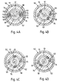
- Figs 2A-2D and 3A-3D depict a typical cycle for the first and second motors 20 and 50 respectively, and show the status of the two motors with respect to each other at various times in the cycle.
- Fig 2C shows an exhaust period for the first motor 20 while Fig 3C, at that same moment, shows a power period for the second motor 50.
- a rolling vane rod 71 which abuts an exterior surface 72 of the rotor 23 and a portion 74 of a rod recess 75.
- a seal 76 on a lobe 77 of the rotor 23 sealingly abuts an interior surface of the stator 21.
- the rotor 23 has moved to a point near the end of a power period.
- the second motor 50 operates as does the first motor 20; but, as preferred, and as shown in Figs 3A-3D, the two motors are out of phase by 90° so that as one motor is exhausting motive fluid the other is providing power.
- the seals 76 are, in one embodiment, made of polyethylethylketone (PEEK).
- the rolling vane rods 71 are also made from PEEK.
- the rotors (23, 25) and stators (21, 51) are preferably made from corrosion resistant materials such as stainless steel.
- the drilling motor 310 comprises two motors 20,50, with suitable adaptation, the drilling motor 310 may comprise only one motor 20 or 50.
- FIG 5 there is shown a second embodiment of an underwater excavation apparatus 300b according to the present invention.
- Like parts of the apparatus 300a are identified by numerals used to identify parts of the apparatus 300a of Fig 1, except subscripted with "b" rather than "a".
- the apparatus 300b differs from the apparatus 300a in that the shaft 342a and swivel 325a are replaced by a second motor 310'b and a T-coupling 326b.
- the impellers 335b, 340b are driven by respective motors 310b, 310'b.
- motive fluid is supplied to motors 310b, 310'b via fluid inlet 308b and T-coupling 326b.
- FIG 6 there is shown a second embodiment of an underwater excavation apparatus 300c according to the present invention.
- Like parts of the apparatus 300b are identified by numerals used to identify parts of the apparatus 300b of Fig 5, except subscripted with "c" rather than "b".
- the apparatus 300c differs from the apparatus 300b in that whereas in apparatus 300b the inlets 371b are horizontally opposed, in apparatus 300c the inlets are substantially symmetrically disposed around an axis extending from outlet 373c, such that the apparatus 300c is substantially "Y" shaped. In this embodiment there is, therefore, provided a Y-coupling 326c.
- drilling motor 310 is suitable for use in any of the disclosed embodiments.
Landscapes
- Engineering & Computer Science (AREA)
- Mechanical Engineering (AREA)
- Mining & Mineral Resources (AREA)
- Civil Engineering (AREA)
- General Engineering & Computer Science (AREA)
- Structural Engineering (AREA)
- Earth Drilling (AREA)
Claims (23)
- Unterwasserbaggervorrichtung (300a; 300b; 300c), die aufweist: einen hohlen Körper (370a; 370b; 370c) mit mindestens zwei Eintrittsöffnungen (371a; 371b; 371c) und mindestens einer Austrittsöffnung (373a; 373b; 373c); mindestens ein Paar Schaufelräder (335a; 335b; 335c; 340a; 340b; 340c), die drehbar im hohlen Körper montiert sind; und eine Einrichtung für das Antreiben der Schaufelräder (310a; 310b; 310c), worin die mindestens zwei Eintrittsöffnungen im wesentlichen symmetrisch um eine Achse herum angeordnet sind, die sich von der mindestens einen Austrittsöffnung erstreckt.
- Unterwasserbaggervorrichtung nach Anspruch 1, bei der die Antriebseinrichtung bewirkt, daß die Schaufelräder in gegenläufigen Richtungen angetrieben werden.
- Unterwasserbaggervorrichtung nach beiden der Ansprüche 1 und 2, bei der eines der Schaufelräder innerhalb einer der Eintrittsöffnungen verhanden ist, und bei der das andere der Schaufelräder innerhalb der anderen der Eintrittsöffnungen vorhanden ist.
- Unterwasserbaggervorrichtung nach einem der Ansprüche 1 bis 3, bei der ein Paar Eintrittsöffnungen vorhanden ist.
- Unterwasserbaggervorrichtung nach einem der Ansprüche 1 bis 4, bei der die Vorrichtung ein Paar horizontal gegenüberliegende Eintrittsöffnungen (371c) aufweist, die mit einer einzelnen Austrittsöffnung (373c) in Verbindung stehen, wobei die Austrittsöffnung vertikal nach unten im wesentlichen in der Mitte zwischen den zwei Eintrittsöffnungen bei der Benutzung angeordnet ist, so daß die Baggervorrichtung im wesentlichen ein "T"-förmiges Profil aufweist.
- Unterwasserbaggervorrichtung nach einem der Ansprüche 1 bis 4, bei der die Vorrichtung ein Paar Eintrittsöffnungen (371c) aufweist, die mit einer einzelnen Austrittsöffnung (373c) in Verbindung stehen, wobei die Eintrittsöffnungen im wesentlichen symmetrisch um eine Achse herum angeordnet sind, die sich von der Austrittsöffnung erstreckt, wobei die Austrittsöffnung vertikal nach unten im wesentlichen in der Mitte zwischen den zwei Eintrittsöffnungen bei der Benutzung angeordnet ist, so daß die Baggervorrichtung im wesentlichen ein "Y"-förmiges Profil aufweist.
- Unterwasserbaggervorrichtung nach einem der Ansprüche 1 bis 6, bei der mindestens ein Schaufelrad (335a; 335b; 335c; 340a; 340b; 340c) innerhalb einer jeden Austrittsöffnung vorhanden ist.
- Unterwasserbaggervorrichtung nach einem der Ansprüche 1 bis 7, bei der die Einrichtung für das Antreiben der Schaufelräder (335a; 335b; 335c; 340a; 340b; 340c) mindestens einen Bohrmotor (310a; 310b; 310c) umfaßt.
- Unterwasserbaggervorrichtung nach Anspruch 8, bei der der mindestens eine Bohrmotor (310a; 310b; 310c) einen Stator (21, 51) und einen Rotor (23, 53), der im Stator drehbar montiert ist, aufweist, wobei der Stator mit einer Stangenaussparung (75) und einem Austrittsschlitz (33, 63) versehen ist, wobei der Rotor mit einem Rotorkanal (27, 57) und mindestens einem Kanal (28, 58) für das Leiten von Antriebsfluid vom Rotorkanal zu einer Kammer (31; 21) zwischen dem Rotor und dem Stator versehen ist, wobei die Stangenaussparung mit einer Stange (71) versehen ist, die bei der Benutzung eine Dichtung zwischen dem Stator und dem Rotor bildet.
- Unterwasserbaggervorrichtung nach Anspruch 9, bei der der Rotor mit einer Dichtung (76) für einen Eingriff mit dem Stator versehen ist.
- Unterwasserbaggervorrichtung nach Anspruch 10, bei der die Dichtung aus einem Material besteht, das aus der Gruppe ausgewählt wird, die besteht aus: Kunststoffmaterialien; Polyethylethylketon; Metall; Kupferlegierungen; und nichtrostendem Stahl.
- Unterwasserbaggervorrichtung nach einem der Ansprüche 9 bis 11, bei der der Stator (21, 51) mit zwei Stangenaussparungen (75), die einander gegenüberliegend angeordnet sind, und zwei Austrittsschlitzen (33, 63) versehen ist, die einander gegenüberliegend angeordnet sind, wobei jede der Stangenaussparungen mit einer entsprechenden Stange (71) versehen ist, wobei der Rotor zwei Dichtungen (76) aufweist, die einander gegenüberliegend angeordnet sind.
- Unterwasserbaggervorrichtung nach einem der Ansprüche 9 bis 12, bei der die Stange aus einem Material besteht, das aus der Gruppe ausgewählt wird, die besteht aus: Kunststoffmaterialien; Polyethylethylketon; Metall; Kupferlegierungen; und nichtrostendem Stahl.
- Unterwasserbaggervorrichtung nach einem der Ansprüche 1 bis 13, bei der der mindestens eine Bohrmotor (310a; 310b; 310c) zwei Bohrmotoren (20, 50) aufweist, die so angeordnet sind, daß ihre entsprechenden Rotoren (23, 53) miteinander verbunden sind, wobei jeder Motor einen Stator (21, 51) und einen Rotor (23, 53) aufweist, der drehbar im Stator montiert ist, wobei der Stator mit einer Stangenaussparung (75) und einem Austrittsschlitz (33, 63) versehen ist, wobei der Rotor mit einem Rotorkanal (27, 57) und mindestens einem Kanal (28, 58) für das Leiten von Antriebsfluid vom Rotorkanal zu einer Kammer (31; 32) zwischen dem Rotor und dem Stator versehen ist, wobei die Stangenaussparung (71) mit einer Stange versehen ist, die bei der Benutzung eine Dichtung zwischen dem Stator und dem Rotor bildet.
- Unterwasserbaggervorrichtung nach Anspruch 14, bei der die Bohrmotoren parallel oder in Reihe geschaltet sind.
- Unterwasserbaggervorrichtung nach entweder Anspruch 14 oder 15, bei der die Bohrmotoren so angeordnet sind, daß bei Benutzung ein Bohrmotor außer Phase mit dem anderen arbeitet.
- Unterwasserbaggervorrichtung nach einem der Ansprüche 1 bis 15, bei der die Schaufelräder mittels eines Getriebes oder durch Ausnutzung des Gegendrehmomentes auf einen Antriebskörper von mindestens einem Motor angetrieben werden.
- Unterwasserbaggervorrichtung nach Anspruch 17, bei der das Gegendrehmoment auf den Antriebskörper genutzt wird, wobei mindestens ein weiteres Schaufelrad mit dem Antriebskörper verbunden ist.
- Unterwasserbaggervorrichtung nach einem der Ansprüche 1 bis 18, bei der die Schaufelräder mittels eines Paares von Motoren angetrieben werden, die in entgegengesetzten Richtungen arbeiten.
- Unterwasserbaggervorrichtung nach einem der Ansprüche 1 bis 19, bei der die Unterwasserbaggervorrichtung außerdem eine Rührvorrichtung mit einer mechanischen Störeinrichtung und einer Fluidstromstöreinrichtung aufweist.
- Unterwasserbaggervorrichtung nach einem der Ansprüche 1 bis 20, bei der bei Benutzung die Unterwasserbaggervorrichtung von einem Überwasserfahrzeug herabhängt oder auf einem Schlitten montiert ist.
- Unterwasserbaggervorrichtung nach einem der Ansprüche, bei der die Austrittsöffnungen jeweils im wesentlichen 45° von der Achse geneigt sind, die sich von der Austrittsöffnung erstreckt.
- Unterwasserbaggervorrichtung die aufweist: einen hohlen Körper (310a; 310b; 310c) mit mindestens zwei Eintrittsöffnungen (371a; 371b; 371c), die mit einer Austrittsöffnung (373a; 373b; 373c) in Verbindung stehen; mindestens ein Paar Schaufelräder (335a; 335b; 335c; 340a; 340b; 340c), die drehbar im hohlen Körper montiert sind; und eine Einrichtung für das Antreiben der Schaufelräder, wobei die Eintrittsöffnungen im wesentlichen symmetrisch um eine Achse angeordnet sind, die sich von der Austrittsöffnung erstreckt, wobei die Eintrittsöffnungen nicht horizontal einander gegenüberliegen.
Applications Claiming Priority (2)
| Application Number | Priority Date | Filing Date | Title |
|---|---|---|---|
| GBGB9512602.5A GB9512602D0 (en) | 1995-06-21 | 1995-06-21 | Improvements in or relating to underwater excavation apparatus |
| PCT/GB1996/003148 WO1998027286A1 (en) | 1995-06-21 | 1996-12-19 | Improvements in or relating to underwater excavation apparatus |
Publications (2)
| Publication Number | Publication Date |
|---|---|
| EP1007796A1 EP1007796A1 (de) | 2000-06-14 |
| EP1007796B1 true EP1007796B1 (de) | 2003-11-12 |
Family
ID=26307254
Family Applications (1)
| Application Number | Title | Priority Date | Filing Date |
|---|---|---|---|
| EP96942501A Expired - Lifetime EP1007796B1 (de) | 1995-06-21 | 1996-12-19 | Verbesserungen bezüglich einer unterwasserbaggervorrichtung |
Country Status (5)
| Country | Link |
|---|---|
| US (1) | US6430848B1 (de) |
| EP (1) | EP1007796B1 (de) |
| KR (1) | KR20000057696A (de) |
| GB (2) | GB9512602D0 (de) |
| WO (1) | WO1998027286A1 (de) |
Cited By (2)
| Publication number | Priority date | Publication date | Assignee | Title |
|---|---|---|---|---|
| WO2008065360A1 (en) * | 2006-11-29 | 2008-06-05 | Rotech Holdings Limited | Underwater excavation apparatus |
| EP4036321A1 (de) | 2016-08-24 | 2022-08-03 | Rotech Group Limited | Verbesserungen an oder im zusammenhang mit einer unterwasseraushubvorrichtung |
Families Citing this family (11)
| Publication number | Priority date | Publication date | Assignee | Title |
|---|---|---|---|---|
| GB9512602D0 (en) * | 1995-06-21 | 1995-08-23 | Susman Hector F A | Improvements in or relating to underwater excavation apparatus |
| DK1007796T3 (da) * | 1996-12-19 | 2004-03-22 | Rotech Holdings Ltd | Forbedringer ved eller vedrørende en undervandsgraveanordning |
| GB0026818D0 (en) | 2000-11-02 | 2000-12-20 | Rotech Holdings Ltd | Fluid machine |
| GB0104642D0 (en) * | 2001-02-26 | 2001-04-11 | Wilkinson Michael J | The movement of silt sludge or other materials utilising a Venturi or vertex effect |
| GB0123802D0 (en) | 2001-10-04 | 2001-11-21 | Rotech Holdings Ltd | Power generator and turbine unit |
| US20100139130A1 (en) * | 2008-12-08 | 2010-06-10 | Wagenaar Dirk C | Underwater Excavation Tool |
| GB2474891B (en) * | 2009-10-30 | 2015-02-18 | Rotech Ltd | Underwater excavation apparatus |
| CN107090863A (zh) * | 2017-05-22 | 2017-08-25 | 湖南省远扬环保科技有限公司 | 多功能河道清淤机 |
| GB2570167B (en) * | 2018-04-20 | 2020-07-29 | Rotech Group Ltd | Improvements in and relating to underwater excavation apparatus |
| FR3086703B1 (fr) * | 2018-09-27 | 2020-11-06 | Agence Nat Pour La Gestion Des Dechets Radioactifs | Moteur hydraulique a eau |
| GB2614897B (en) | 2022-01-21 | 2024-09-04 | Rotech Group Ltd | Improvements in and relating to underwater excavation apparatus |
Family Cites Families (9)
| Publication number | Priority date | Publication date | Assignee | Title |
|---|---|---|---|---|
| US3235232A (en) * | 1964-04-27 | 1966-02-15 | Black Sivalls & Bryson Inc | Material agitator device and method of agitation |
| US4914841A (en) * | 1986-12-24 | 1990-04-10 | Eddy Pump Corporation | Dredging with a pressurized, rotating liquid stream |
| GB8802907D0 (en) * | 1988-02-09 | 1988-03-09 | Burring P J | Wing dredger |
| US4957392A (en) | 1989-04-27 | 1990-09-18 | Bailard James A | Method and apparatus for the active prevention of sedimentation in harbors and waterways |
| GB9002532D0 (en) * | 1990-02-05 | 1990-04-04 | Consortium Resource Management | Improvements in or relating to underwater excavation apparatus |
| US5833444A (en) * | 1994-01-13 | 1998-11-10 | Harris; Gary L. | Fluid driven motors |
| US6022173A (en) * | 1994-01-13 | 2000-02-08 | Saxon; Saint E. | Underwater trenching system |
| GB2297777A (en) * | 1995-02-07 | 1996-08-14 | Hollandsche Betongroep Nv | Underwater excavation apparatus |
| GB9512602D0 (en) * | 1995-06-21 | 1995-08-23 | Susman Hector F A | Improvements in or relating to underwater excavation apparatus |
-
1995
- 1995-06-21 GB GBGB9512602.5A patent/GB9512602D0/en active Pending
-
1996
- 1996-06-20 GB GB9612969A patent/GB2302348B/en not_active Expired - Lifetime
- 1996-12-19 KR KR1019990705556A patent/KR20000057696A/ko not_active Withdrawn
- 1996-12-19 WO PCT/GB1996/003148 patent/WO1998027286A1/en not_active Ceased
- 1996-12-19 US US09/331,151 patent/US6430848B1/en not_active Expired - Lifetime
- 1996-12-19 EP EP96942501A patent/EP1007796B1/de not_active Expired - Lifetime
Cited By (7)
| Publication number | Priority date | Publication date | Assignee | Title |
|---|---|---|---|---|
| WO2008065360A1 (en) * | 2006-11-29 | 2008-06-05 | Rotech Holdings Limited | Underwater excavation apparatus |
| GB2455958A (en) * | 2006-11-29 | 2009-07-01 | Rotech Holdings Ltd | Underwater excavation apparatus |
| GB2444259B (en) * | 2006-11-29 | 2011-03-02 | Rotech Holdings Ltd | Improvements in and relating to underwater excavation apparatus |
| GB2455958B (en) * | 2006-11-29 | 2011-07-20 | Rotech Holdings Ltd | Underwater excavation apparatus |
| US8893408B2 (en) | 2006-11-29 | 2014-11-25 | Rotech Limited | Underwater excavation apparatus |
| EP4036321A1 (de) | 2016-08-24 | 2022-08-03 | Rotech Group Limited | Verbesserungen an oder im zusammenhang mit einer unterwasseraushubvorrichtung |
| EP4036322A1 (de) | 2016-08-24 | 2022-08-03 | Rotech Group Limited | Verbesserungen an oder im zusammenhang mit einer unterwasseraushubvorrichtung |
Also Published As
| Publication number | Publication date |
|---|---|
| GB9512602D0 (en) | 1995-08-23 |
| GB2302348A (en) | 1997-01-15 |
| EP1007796A1 (de) | 2000-06-14 |
| GB2302348B (en) | 1998-11-11 |
| WO1998027286A1 (en) | 1998-06-25 |
| US6430848B1 (en) | 2002-08-13 |
| KR20000057696A (ko) | 2000-09-25 |
| GB9612969D0 (en) | 1996-08-21 |
Similar Documents
| Publication | Publication Date | Title |
|---|---|---|
| EP1007796B1 (de) | Verbesserungen bezüglich einer unterwasserbaggervorrichtung | |
| US5833444A (en) | Fluid driven motors | |
| EP0736128B1 (de) | Bohrlochmotor für bohrgeräte | |
| US8388327B2 (en) | Progressing cavity pump with several pump sections | |
| GB2297777A (en) | Underwater excavation apparatus | |
| EP0201500A1 (de) | Vorrichtung bei flüssigdruckgeneratoren. | |
| AU2007327072B2 (en) | Underwater excavation apparatus | |
| CA2275578C (en) | Improvements in or relating to underwater excavation apparatus | |
| US4676716A (en) | Hydraulic multistage turbine of turbodrill | |
| EP0274368B1 (de) | Rotierende Abdichtung | |
| US4606700A (en) | Turbodrill multistage turbine | |
| CN1123693C (zh) | 切向射流力驱动回转式流体-机械能转换装置 | |
| CN1033535A (zh) | 电机叶轮连体泵 | |
| EP0249175A2 (de) | Pumpe | |
| CN1101766C (zh) | 立式水力喷射推进装置 | |
| MXPA99005761A (en) | Improvements in or relating to underwater excavation apparatus | |
| GB2305973A (en) | Motor with cam lobed rotor and inlet/exhaust combined with sealing rod recess. | |
| EP0363412A1 (de) | Strahltriebwerk für schiffe. | |
| CA2078849A1 (en) | Motor-driven pump with reaction turbine | |
| GB2301128A (en) | Underwater excavation apparatus | |
| NO308958B1 (no) | En undervannsutgravningsapparatur | |
| RU2195542C1 (ru) | Турбобур | |
| US5577564A (en) | Rotary fluid converter | |
| RU2005889C1 (ru) | Лопастный забойный двигатель | |
| CA2181177C (en) | Downhole motor for a drilling apparatus |
Legal Events
| Date | Code | Title | Description |
|---|---|---|---|
| PUAI | Public reference made under article 153(3) epc to a published international application that has entered the european phase |
Free format text: ORIGINAL CODE: 0009012 |
|
| 17P | Request for examination filed |
Effective date: 19990625 |
|
| AK | Designated contracting states |
Kind code of ref document: A1 Designated state(s): BE DE DK ES FI FR GB GR IE IT MC NL PT SE |
|
| 17Q | First examination report despatched |
Effective date: 20010402 |
|
| GRAG | Despatch of communication of intention to grant |
Free format text: ORIGINAL CODE: EPIDOS AGRA |
|
| GRAG | Despatch of communication of intention to grant |
Free format text: ORIGINAL CODE: EPIDOS AGRA |
|
| GRAH | Despatch of communication of intention to grant a patent |
Free format text: ORIGINAL CODE: EPIDOS IGRA |
|
| GRAH | Despatch of communication of intention to grant a patent |
Free format text: ORIGINAL CODE: EPIDOS IGRA |
|
| RAP1 | Party data changed (applicant data changed or rights of an application transferred) |
Owner name: ROTECH HOLDINGS LIMITED |
|
| GRAA | (expected) grant |
Free format text: ORIGINAL CODE: 0009210 |
|
| AK | Designated contracting states |
Kind code of ref document: B1 Designated state(s): BE DE DK ES FI FR GB GR IE IT MC NL PT SE |
|
| PG25 | Lapsed in a contracting state [announced via postgrant information from national office to epo] |
Ref country code: IT Free format text: LAPSE BECAUSE OF FAILURE TO SUBMIT A TRANSLATION OF THE DESCRIPTION OR TO PAY THE FEE WITHIN THE PRE;WARNING: LAPSES OF ITALIAN PATENTS WITH EFFECTIVE DATE BEFORE 2007 MAY HAVE OCCURRED AT ANY TIME BEFORE 2007. THE CORRECT EFFECTIVE DATE MAY BE DIFFERENT FROM THE ONE RECORDED.SCRIBED TIME-LIMIT Effective date: 20031112 Ref country code: FI Free format text: LAPSE BECAUSE OF FAILURE TO SUBMIT A TRANSLATION OF THE DESCRIPTION OR TO PAY THE FEE WITHIN THE PRESCRIBED TIME-LIMIT Effective date: 20031112 |
|
| REG | Reference to a national code |
Ref country code: GB Ref legal event code: FG4D |
|
| PGFP | Annual fee paid to national office [announced via postgrant information from national office to epo] |
Ref country code: FI Payment date: 20031212 Year of fee payment: 8 |
|
| REF | Corresponds to: |
Ref document number: 69630716 Country of ref document: DE Date of ref document: 20031218 Kind code of ref document: P |
|
| PGFP | Annual fee paid to national office [announced via postgrant information from national office to epo] |
Ref country code: ES Payment date: 20031219 Year of fee payment: 8 |
|
| PGFP | Annual fee paid to national office [announced via postgrant information from national office to epo] |
Ref country code: GR Payment date: 20031222 Year of fee payment: 8 |
|
| PGFP | Annual fee paid to national office [announced via postgrant information from national office to epo] |
Ref country code: SE Payment date: 20031229 Year of fee payment: 8 |
|
| PG25 | Lapsed in a contracting state [announced via postgrant information from national office to epo] |
Ref country code: MC Free format text: LAPSE BECAUSE OF NON-PAYMENT OF DUE FEES Effective date: 20031231 |
|
| REG | Reference to a national code |
Ref country code: IE Ref legal event code: FG4D |
|
| PG25 | Lapsed in a contracting state [announced via postgrant information from national office to epo] |
Ref country code: SE Free format text: LAPSE BECAUSE OF FAILURE TO SUBMIT A TRANSLATION OF THE DESCRIPTION OR TO PAY THE FEE WITHIN THE PRESCRIBED TIME-LIMIT Effective date: 20040212 Ref country code: GR Free format text: LAPSE BECAUSE OF FAILURE TO SUBMIT A TRANSLATION OF THE DESCRIPTION OR TO PAY THE FEE WITHIN THE PRESCRIBED TIME-LIMIT Effective date: 20040212 |
|
| PG25 | Lapsed in a contracting state [announced via postgrant information from national office to epo] |
Ref country code: ES Free format text: LAPSE BECAUSE OF FAILURE TO SUBMIT A TRANSLATION OF THE DESCRIPTION OR TO PAY THE FEE WITHIN THE PRESCRIBED TIME-LIMIT Effective date: 20040223 |
|
| REG | Reference to a national code |
Ref country code: DK Ref legal event code: T3 |
|
| ET | Fr: translation filed | ||
| PLBE | No opposition filed within time limit |
Free format text: ORIGINAL CODE: 0009261 |
|
| STAA | Information on the status of an ep patent application or granted ep patent |
Free format text: STATUS: NO OPPOSITION FILED WITHIN TIME LIMIT |
|
| 26N | No opposition filed |
Effective date: 20040813 |
|
| PGFP | Annual fee paid to national office [announced via postgrant information from national office to epo] |
Ref country code: DE Payment date: 20061214 Year of fee payment: 11 |
|
| PG25 | Lapsed in a contracting state [announced via postgrant information from national office to epo] |
Ref country code: PT Free format text: LAPSE BECAUSE OF NON-PAYMENT OF DUE FEES Effective date: 20040412 |
|
| PG25 | Lapsed in a contracting state [announced via postgrant information from national office to epo] |
Ref country code: DE Free format text: LAPSE BECAUSE OF NON-PAYMENT OF DUE FEES Effective date: 20080701 |
|
| PGFP | Annual fee paid to national office [announced via postgrant information from national office to epo] |
Ref country code: BE Payment date: 20111229 Year of fee payment: 16 |
|
| REG | Reference to a national code |
Ref country code: GB Ref legal event code: 732E Free format text: REGISTERED BETWEEN 20120517 AND 20120523 |
|
| REG | Reference to a national code |
Ref country code: NL Ref legal event code: SD Effective date: 20121119 |
|
| REG | Reference to a national code |
Ref country code: FR Ref legal event code: TP Owner name: ROTECH LIMITED, GB Effective date: 20121206 Ref country code: FR Ref legal event code: CL Name of requester: REEF SUBSEA UK LIMITED, GB Effective date: 20121206 |
|
| BERE | Be: lapsed |
Owner name: *ROTECH HOLDINGS LTD Effective date: 20121231 |
|
| PG25 | Lapsed in a contracting state [announced via postgrant information from national office to epo] |
Ref country code: BE Free format text: LAPSE BECAUSE OF NON-PAYMENT OF DUE FEES Effective date: 20121231 |
|
| REG | Reference to a national code |
Ref country code: FR Ref legal event code: PLFP Year of fee payment: 20 |
|
| REG | Reference to a national code |
Ref country code: GB Ref legal event code: 732E Free format text: REGISTERED BETWEEN 20151119 AND 20151125 |
|
| PGFP | Annual fee paid to national office [announced via postgrant information from national office to epo] |
Ref country code: DK Payment date: 20151210 Year of fee payment: 20 Ref country code: IE Payment date: 20151209 Year of fee payment: 20 Ref country code: GB Payment date: 20151216 Year of fee payment: 20 |
|
| PGFP | Annual fee paid to national office [announced via postgrant information from national office to epo] |
Ref country code: NL Payment date: 20151210 Year of fee payment: 20 Ref country code: FR Payment date: 20151110 Year of fee payment: 20 |
|
| REG | Reference to a national code |
Ref country code: NL Ref legal event code: MK Effective date: 20161218 |
|
| REG | Reference to a national code |
Ref country code: DK Ref legal event code: EUP Effective date: 20161219 |
|
| REG | Reference to a national code |
Ref country code: GB Ref legal event code: PE20 Expiry date: 20161218 |
|
| REG | Reference to a national code |
Ref country code: IE Ref legal event code: MK9A |
|
| PG25 | Lapsed in a contracting state [announced via postgrant information from national office to epo] |
Ref country code: GB Free format text: LAPSE BECAUSE OF EXPIRATION OF PROTECTION Effective date: 20161218 |
|
| PG25 | Lapsed in a contracting state [announced via postgrant information from national office to epo] |
Ref country code: IE Free format text: LAPSE BECAUSE OF EXPIRATION OF PROTECTION Effective date: 20161219 |