EP1007832B1 - Device for compressing a gaseous medium and systems comprising such device - Google Patents
Device for compressing a gaseous medium and systems comprising such device Download PDFInfo
- Publication number
- EP1007832B1 EP1007832B1 EP99929945A EP99929945A EP1007832B1 EP 1007832 B1 EP1007832 B1 EP 1007832B1 EP 99929945 A EP99929945 A EP 99929945A EP 99929945 A EP99929945 A EP 99929945A EP 1007832 B1 EP1007832 B1 EP 1007832B1
- Authority
- EP
- European Patent Office
- Prior art keywords
- evaporation agent
- flash
- medium
- compressor
- evaporation
- Prior art date
- Legal status (The legal status is an assumption and is not a legal conclusion. Google has not performed a legal analysis and makes no representation as to the accuracy of the status listed.)
- Expired - Lifetime
Links
Images




Classifications
-
- F—MECHANICAL ENGINEERING; LIGHTING; HEATING; WEAPONS; BLASTING
- F02—COMBUSTION ENGINES; HOT-GAS OR COMBUSTION-PRODUCT ENGINE PLANTS
- F02C—GAS-TURBINE PLANTS; AIR INTAKES FOR JET-PROPULSION PLANTS; CONTROLLING FUEL SUPPLY IN AIR-BREATHING JET-PROPULSION PLANTS
- F02C7/00—Features, components parts, details or accessories, not provided for in, or of interest apart form groups F02C1/00 - F02C6/00; Air intakes for jet-propulsion plants
- F02C7/12—Cooling of plants
- F02C7/14—Cooling of plants of fluids in the plant, e.g. lubricant or fuel
- F02C7/141—Cooling of plants of fluids in the plant, e.g. lubricant or fuel of working fluid
- F02C7/143—Cooling of plants of fluids in the plant, e.g. lubricant or fuel of working fluid before or between the compressor stages
-
- F—MECHANICAL ENGINEERING; LIGHTING; HEATING; WEAPONS; BLASTING
- F04—POSITIVE - DISPLACEMENT MACHINES FOR LIQUIDS; PUMPS FOR LIQUIDS OR ELASTIC FLUIDS
- F04D—NON-POSITIVE-DISPLACEMENT PUMPS
- F04D29/00—Details, component parts, or accessories
- F04D29/58—Cooling; Heating; Diminishing heat transfer
- F04D29/582—Cooling; Heating; Diminishing heat transfer specially adapted for elastic fluid pumps
- F04D29/5846—Cooling; Heating; Diminishing heat transfer specially adapted for elastic fluid pumps cooling by injection
-
- B—PERFORMING OPERATIONS; TRANSPORTING
- B05—SPRAYING OR ATOMISING IN GENERAL; APPLYING FLUENT MATERIALS TO SURFACES, IN GENERAL
- B05B—SPRAYING APPARATUS; ATOMISING APPARATUS; NOZZLES
- B05B9/00—Spraying apparatus for discharge of liquids or other fluent material, without essentially mixing with gas or vapour
- B05B9/005—Spraying apparatus for discharge of liquids or other fluent material, without essentially mixing with gas or vapour the liquid or other fluent material being a fluid close to a change of phase
-
- F—MECHANICAL ENGINEERING; LIGHTING; HEATING; WEAPONS; BLASTING
- F01—MACHINES OR ENGINES IN GENERAL; ENGINE PLANTS IN GENERAL; STEAM ENGINES
- F01K—STEAM ENGINE PLANTS; STEAM ACCUMULATORS; ENGINE PLANTS NOT OTHERWISE PROVIDED FOR; ENGINES USING SPECIAL WORKING FLUIDS OR CYCLES
- F01K21/00—Steam engine plants not otherwise provided for
- F01K21/04—Steam engine plants not otherwise provided for using mixtures of steam and gas; Plants generating or heating steam by bringing water or steam into direct contact with hot gas
- F01K21/047—Steam engine plants not otherwise provided for using mixtures of steam and gas; Plants generating or heating steam by bringing water or steam into direct contact with hot gas having at least one combustion gas turbine
-
- F—MECHANICAL ENGINEERING; LIGHTING; HEATING; WEAPONS; BLASTING
- F02—COMBUSTION ENGINES; HOT-GAS OR COMBUSTION-PRODUCT ENGINE PLANTS
- F02B—INTERNAL-COMBUSTION PISTON ENGINES; COMBUSTION ENGINES IN GENERAL
- F02B51/00—Other methods of operating engines involving pretreating of, or adding substances to, combustion air, fuel, or fuel-air mixture of the engines
-
- F—MECHANICAL ENGINEERING; LIGHTING; HEATING; WEAPONS; BLASTING
- F02—COMBUSTION ENGINES; HOT-GAS OR COMBUSTION-PRODUCT ENGINE PLANTS
- F02C—GAS-TURBINE PLANTS; AIR INTAKES FOR JET-PROPULSION PLANTS; CONTROLLING FUEL SUPPLY IN AIR-BREATHING JET-PROPULSION PLANTS
- F02C7/00—Features, components parts, details or accessories, not provided for in, or of interest apart form groups F02C1/00 - F02C6/00; Air intakes for jet-propulsion plants
- F02C7/12—Cooling of plants
- F02C7/14—Cooling of plants of fluids in the plant, e.g. lubricant or fuel
- F02C7/141—Cooling of plants of fluids in the plant, e.g. lubricant or fuel of working fluid
- F02C7/143—Cooling of plants of fluids in the plant, e.g. lubricant or fuel of working fluid before or between the compressor stages
- F02C7/1435—Cooling of plants of fluids in the plant, e.g. lubricant or fuel of working fluid before or between the compressor stages by water injection
-
- F—MECHANICAL ENGINEERING; LIGHTING; HEATING; WEAPONS; BLASTING
- F02—COMBUSTION ENGINES; HOT-GAS OR COMBUSTION-PRODUCT ENGINE PLANTS
- F02C—GAS-TURBINE PLANTS; AIR INTAKES FOR JET-PROPULSION PLANTS; CONTROLLING FUEL SUPPLY IN AIR-BREATHING JET-PROPULSION PLANTS
- F02C7/00—Features, components parts, details or accessories, not provided for in, or of interest apart form groups F02C1/00 - F02C6/00; Air intakes for jet-propulsion plants
- F02C7/12—Cooling of plants
- F02C7/16—Cooling of plants characterised by cooling medium
- F02C7/18—Cooling of plants characterised by cooling medium the medium being gaseous, e.g. air
- F02C7/185—Cooling means for reducing the temperature of the cooling air or gas
-
- F—MECHANICAL ENGINEERING; LIGHTING; HEATING; WEAPONS; BLASTING
- F02—COMBUSTION ENGINES; HOT-GAS OR COMBUSTION-PRODUCT ENGINE PLANTS
- F02M—SUPPLYING COMBUSTION ENGINES IN GENERAL WITH COMBUSTIBLE MIXTURES OR CONSTITUENTS THEREOF
- F02M25/00—Engine-pertinent apparatus for adding non-fuel substances or small quantities of secondary fuel to combustion-air, main fuel or fuel-air mixture
- F02M25/022—Adding fuel and water emulsion, water or steam
- F02M25/0221—Details of the water supply system, e.g. pumps or arrangement of valves
- F02M25/0225—Water atomisers or mixers, e.g. using ultrasonic waves
-
- F—MECHANICAL ENGINEERING; LIGHTING; HEATING; WEAPONS; BLASTING
- F02—COMBUSTION ENGINES; HOT-GAS OR COMBUSTION-PRODUCT ENGINE PLANTS
- F02M—SUPPLYING COMBUSTION ENGINES IN GENERAL WITH COMBUSTIBLE MIXTURES OR CONSTITUENTS THEREOF
- F02M25/00—Engine-pertinent apparatus for adding non-fuel substances or small quantities of secondary fuel to combustion-air, main fuel or fuel-air mixture
- F02M25/022—Adding fuel and water emulsion, water or steam
- F02M25/025—Adding water
- F02M25/028—Adding water into the charge intakes
-
- F—MECHANICAL ENGINEERING; LIGHTING; HEATING; WEAPONS; BLASTING
- F04—POSITIVE - DISPLACEMENT MACHINES FOR LIQUIDS; PUMPS FOR LIQUIDS OR ELASTIC FLUIDS
- F04D—NON-POSITIVE-DISPLACEMENT PUMPS
- F04D27/00—Control, e.g. regulation, of pumps, pumping installations or pumping systems specially adapted for elastic fluids
- F04D27/02—Surge control
-
- F—MECHANICAL ENGINEERING; LIGHTING; HEATING; WEAPONS; BLASTING
- F25—REFRIGERATION OR COOLING; COMBINED HEATING AND REFRIGERATION SYSTEMS; HEAT PUMP SYSTEMS; MANUFACTURE OR STORAGE OF ICE; LIQUEFACTION SOLIDIFICATION OF GASES
- F25J—LIQUEFACTION, SOLIDIFICATION OR SEPARATION OF GASES OR GASEOUS OR LIQUEFIED GASEOUS MIXTURES BY PRESSURE AND COLD TREATMENT OR BY BRINGING THEM INTO THE SUPERCRITICAL STATE
- F25J3/00—Processes or apparatus for separating the constituents of gaseous or liquefied gaseous mixtures involving the use of liquefaction or solidification
- F25J3/02—Processes or apparatus for separating the constituents of gaseous or liquefied gaseous mixtures involving the use of liquefaction or solidification by rectification, i.e. by continuous interchange of heat and material between a vapour stream and a liquid stream
- F25J3/04—Processes or apparatus for separating the constituents of gaseous or liquefied gaseous mixtures involving the use of liquefaction or solidification by rectification, i.e. by continuous interchange of heat and material between a vapour stream and a liquid stream for air
- F25J3/04006—Providing pressurised feed air or process streams within or from the air fractionation unit
- F25J3/04012—Providing pressurised feed air or process streams within or from the air fractionation unit by compression of warm gaseous streams; details of intake or interstage cooling
- F25J3/04018—Providing pressurised feed air or process streams within or from the air fractionation unit by compression of warm gaseous streams; details of intake or interstage cooling of main feed air
-
- F—MECHANICAL ENGINEERING; LIGHTING; HEATING; WEAPONS; BLASTING
- F25—REFRIGERATION OR COOLING; COMBINED HEATING AND REFRIGERATION SYSTEMS; HEAT PUMP SYSTEMS; MANUFACTURE OR STORAGE OF ICE; LIQUEFACTION SOLIDIFICATION OF GASES
- F25J—LIQUEFACTION, SOLIDIFICATION OR SEPARATION OF GASES OR GASEOUS OR LIQUEFIED GASEOUS MIXTURES BY PRESSURE AND COLD TREATMENT OR BY BRINGING THEM INTO THE SUPERCRITICAL STATE
- F25J3/00—Processes or apparatus for separating the constituents of gaseous or liquefied gaseous mixtures involving the use of liquefaction or solidification
- F25J3/02—Processes or apparatus for separating the constituents of gaseous or liquefied gaseous mixtures involving the use of liquefaction or solidification by rectification, i.e. by continuous interchange of heat and material between a vapour stream and a liquid stream
- F25J3/04—Processes or apparatus for separating the constituents of gaseous or liquefied gaseous mixtures involving the use of liquefaction or solidification by rectification, i.e. by continuous interchange of heat and material between a vapour stream and a liquid stream for air
- F25J3/04763—Start-up or control of the process; Details of the apparatus used
- F25J3/04866—Construction and layout of air fractionation equipments, e.g. valves, machines
- F25J3/04969—Retrofitting or revamping of an existing air fractionation unit
-
- B—PERFORMING OPERATIONS; TRANSPORTING
- B05—SPRAYING OR ATOMISING IN GENERAL; APPLYING FLUENT MATERIALS TO SURFACES, IN GENERAL
- B05B—SPRAYING APPARATUS; ATOMISING APPARATUS; NOZZLES
- B05B1/00—Nozzles, spray heads or other outlets, with or without auxiliary devices such as valves, heating means
- B05B1/34—Nozzles, spray heads or other outlets, with or without auxiliary devices such as valves, heating means designed to influence the nature of flow of the liquid or other fluent material, e.g. to produce swirl
- B05B1/3405—Nozzles, spray heads or other outlets, with or without auxiliary devices such as valves, heating means designed to influence the nature of flow of the liquid or other fluent material, e.g. to produce swirl to produce swirl
- B05B1/341—Nozzles, spray heads or other outlets, with or without auxiliary devices such as valves, heating means designed to influence the nature of flow of the liquid or other fluent material, e.g. to produce swirl to produce swirl before discharging the liquid or other fluent material, e.g. in a swirl chamber upstream the spray outlet
- B05B1/3421—Nozzles, spray heads or other outlets, with or without auxiliary devices such as valves, heating means designed to influence the nature of flow of the liquid or other fluent material, e.g. to produce swirl to produce swirl before discharging the liquid or other fluent material, e.g. in a swirl chamber upstream the spray outlet with channels emerging substantially tangentially in the swirl chamber
- B05B1/3426—Nozzles, spray heads or other outlets, with or without auxiliary devices such as valves, heating means designed to influence the nature of flow of the liquid or other fluent material, e.g. to produce swirl to produce swirl before discharging the liquid or other fluent material, e.g. in a swirl chamber upstream the spray outlet with channels emerging substantially tangentially in the swirl chamber the channels emerging in the swirl chamber perpendicularly to the outlet axis
-
- F—MECHANICAL ENGINEERING; LIGHTING; HEATING; WEAPONS; BLASTING
- F05—INDEXING SCHEMES RELATING TO ENGINES OR PUMPS IN VARIOUS SUBCLASSES OF CLASSES F01-F04
- F05D—INDEXING SCHEME FOR ASPECTS RELATING TO NON-POSITIVE-DISPLACEMENT MACHINES OR ENGINES, GAS-TURBINES OR JET-PROPULSION PLANTS
- F05D2260/00—Function
- F05D2260/20—Heat transfer, e.g. cooling
- F05D2260/212—Heat transfer, e.g. cooling by water injection
-
- F—MECHANICAL ENGINEERING; LIGHTING; HEATING; WEAPONS; BLASTING
- F25—REFRIGERATION OR COOLING; COMBINED HEATING AND REFRIGERATION SYSTEMS; HEAT PUMP SYSTEMS; MANUFACTURE OR STORAGE OF ICE; LIQUEFACTION SOLIDIFICATION OF GASES
- F25J—LIQUEFACTION, SOLIDIFICATION OR SEPARATION OF GASES OR GASEOUS OR LIQUEFIED GASEOUS MIXTURES BY PRESSURE AND COLD TREATMENT OR BY BRINGING THEM INTO THE SUPERCRITICAL STATE
- F25J2230/00—Processes or apparatus involving steps for increasing the pressure of gaseous process streams
- F25J2230/02—Compressor intake arrangement, e.g. filtering or cooling
-
- F—MECHANICAL ENGINEERING; LIGHTING; HEATING; WEAPONS; BLASTING
- F25—REFRIGERATION OR COOLING; COMBINED HEATING AND REFRIGERATION SYSTEMS; HEAT PUMP SYSTEMS; MANUFACTURE OR STORAGE OF ICE; LIQUEFACTION SOLIDIFICATION OF GASES
- F25J—LIQUEFACTION, SOLIDIFICATION OR SEPARATION OF GASES OR GASEOUS OR LIQUEFIED GASEOUS MIXTURES BY PRESSURE AND COLD TREATMENT OR BY BRINGING THEM INTO THE SUPERCRITICAL STATE
- F25J2230/00—Processes or apparatus involving steps for increasing the pressure of gaseous process streams
- F25J2230/04—Compressor cooling arrangement, e.g. inter- or after-stage cooling or condensate removal
-
- Y—GENERAL TAGGING OF NEW TECHNOLOGICAL DEVELOPMENTS; GENERAL TAGGING OF CROSS-SECTIONAL TECHNOLOGIES SPANNING OVER SEVERAL SECTIONS OF THE IPC; TECHNICAL SUBJECTS COVERED BY FORMER USPC CROSS-REFERENCE ART COLLECTIONS [XRACs] AND DIGESTS
- Y02—TECHNOLOGIES OR APPLICATIONS FOR MITIGATION OR ADAPTATION AGAINST CLIMATE CHANGE
- Y02T—CLIMATE CHANGE MITIGATION TECHNOLOGIES RELATED TO TRANSPORTATION
- Y02T10/00—Road transport of goods or passengers
- Y02T10/10—Internal combustion engine [ICE] based vehicles
- Y02T10/12—Improving ICE efficiencies
-
- Y—GENERAL TAGGING OF NEW TECHNOLOGICAL DEVELOPMENTS; GENERAL TAGGING OF CROSS-SECTIONAL TECHNOLOGIES SPANNING OVER SEVERAL SECTIONS OF THE IPC; TECHNICAL SUBJECTS COVERED BY FORMER USPC CROSS-REFERENCE ART COLLECTIONS [XRACs] AND DIGESTS
- Y02—TECHNOLOGIES OR APPLICATIONS FOR MITIGATION OR ADAPTATION AGAINST CLIMATE CHANGE
- Y02T—CLIMATE CHANGE MITIGATION TECHNOLOGIES RELATED TO TRANSPORTATION
- Y02T50/00—Aeronautics or air transport
- Y02T50/60—Efficient propulsion technologies, e.g. for aircraft
Definitions
- the present invention concerns a device for the compressing of a gaseous medium and systems that apply such compressing devices, such as energy generating systems, gas separators, compressors and compressor systems for natural gas, air, and chemicals - such as ammoniac.
- compressing devices such as energy generating systems, gas separators, compressors and compressor systems for natural gas, air, and chemicals - such as ammoniac.
- Compressing a gaseous medium requires compression work, which work is directly proportional to the absolute temperature of the medium to be compressed. This means that compression work may be reduced by cooling the medium before and during the compression and in the event of recycling also after compression. This applies also if the medium is compressed successively in various stages.
- the main objective is a virtually ideal or quasi-isothermal compression.
- the medium is cooled by introducing a liquid evaporation agent (usually water).
- a liquid evaporation agent usually water
- the evaporation agent is introduced in the form of droplets that evaporate.
- the heat required for evaporation is provided by the medium, which consequently cools.
- the objective is to introduce as tiny droplets as possible (1-10 ⁇ m).
- the smaller the droplets the likelier the possibility that they will evaporate completely, but also the less likely that they will come into contact with the structure of the compressor unit.
- the medium has a high velocity and/or the air residence time in the compressor unit is short, there usually is insufficient time for full evaporation.
- DE-A-41 14 678 relates to a method for the atomisation of a fluid for a gas turbine.
- the atomisation of the fluid has to take place over the entire length of the compressor at a spraying pressure of 5-20 bar above the compressor pressure.
- the maximum quantity of fluid to be atomised - water in particular - lies between 0 to 0.2 kilogram per kilogram air and may not be exceeded.
- US-A-4 478 553 relates to the isothermal compression in the compressor of a gas turbine.
- Atomising means are strategically positioned in the rotor structure.
- the water to be dispersed is not pre-heated and the size of the droplets of the atomised evaporation agent is preferably maintained at between 2 and 10 ⁇ m.
- US-A-5 388 397 relates to a method for operating a turbocompressor, whereby air is compressed in two stages and cooled in between in an intercooler.
- the warm water of the intercooler is cooled in subsequent evaporating vessels and the resulting steam is transferred very compactly to the environment by spontaneous evaporation according to a flash method.
- the evaporated amount is made up to by a corresponding amount of fresh water.
- EP-A 0 821 137 describes a system for generating energy, whereby the gas to be compressed is cooled by atomising water droplets with a drop size of 1-5 ⁇ m. Under certain conditions, however, the required flow rate of atomised water droplets is too small.
- the present invention aims to provide a compressor device in which a gaseous medium may be compressed at relatively low temperatures by applying very small droplets of evaporation agent (the median is smaller than 5 ⁇ m, generally smaller than 3 ⁇ m, preferably smaller than 2 ⁇ m, e.g. 1.2 ⁇ m) whereas sufficient flow rate of this type of atomised droplets may be generated in dependency of the flow rate of the medium to be compressed.
- very small droplets of evaporation agent the median is smaller than 5 ⁇ m, generally smaller than 3 ⁇ m, preferably smaller than 2 ⁇ m, e.g. 1.2 ⁇ m
- the present invention aims to provide a very adequate manner of cooling a gaseous medium, so that the cooling capacity of existing or required gas coolers (intercoolers) may be reduced or that they may be replaced.
- a device for compressing a gaseous medium comprising a compressor unit provided with a medium inlet, an outlet for the compressed medium and of means for atomising a liquid evaporation agent in the medium, characterised in that the atomising means comprise at least one flash atomisation unit, mounted and arranged such, that the atomised evaporation agent fragmentises by the formation of gas in the atomised evaporation agent.
- the atomising means of this compressor unit comprise an inlet for evaporation agent and an outlet for evaporation agent into the gaseous medium line. It is possible that this gaseous medium still has to be compressed, is in the process of being compressed or has already been compressed. In the latter instance, the compressed medium may still be added to a subsequent compressing unit or may in part be recirculated.
- the atomising means usually also contain a very large number of atomisers via which the evaporation agent is sprayed into the gaseous medium.
- any known type of atomiser may be used in the flash atomisation unit. Suitable ones are, for example, swirl atomisers, slot atomisers, orifice atomisers, rotating bowl atomisers and, if necessary, pen atomisers. Of importance is only that the atomiser gives off droplets or a film of evaporation agent to the gaseous medium, under circumstances changed to such extent that flash atomisation takes place subsequently. Flash atomisation means that the liquid evaporation agent arrives in the gaseous medium under such conditions that as a result of the pressure drop over the atomiser, boiling bubbles or gas bubbles are generated in the droplets or film of the evaporation agent, i.e.
- the median size of the evaporation agent is less than 5 ⁇ m, in general smaller than 3 ⁇ m, preferably smaller than 2 ⁇ m, e.g. 1.2 ⁇ m.
- atomisers may be employed in the atomising means insofar as they result in droplets of the said median size after fragmentation.
- the atomising means the flash atomisation units in particular, are mounted and arranged such that the atomised evaporation agent fragmentises by the generation of gas in the atomised evaporation agent.
- a flash atomisation unit is used that is provided with swirl atomisers.
- the evaporation agent is put in swirling motion in a swirl chamber.
- the swirling evaporation agent exits via an outlet.
- the thickness of the exiting layer of evaporation agent is only a fraction (e.g. 10%) of the diameter of the outlet passage.
- the subsequent flash fragmentation results in droplets having (dependent on the pressure drop, temperature and diameter of the outlet passage) a median size of 5 ⁇ m or less. Because of the reduced size of the droplets of evaporation agent, there will be less risk of contact with the interior of the compressor unit, which means that the entire length of the compressor unit can be cooled.
- the flash atomisation unit preferably comprises means for adjusting the temperature of the evaporation agent and/or the atomisation pressure.
- known atomisers may, in principle, be used in the compressor device according to the invention. These atomisers may release the evaporation agent in the gaseous medium in a direction which is either traverse or parallel to the flow of the gaseous medium.
- the atomised evaporation agent may possess a radial or axial component vis-à-vis the gaseous medium.
- a radial component is important in order to avoid coalescence of the fragmentised droplets of evaporation agent and may be realised e.g. by applying a swirl atomiser.
- An axial component is important in order to transfer the energy of the evaporation agent as much as possible to the gaseous medium, such that the pressure drop is low or even negative.
- a spraying rack with swirl atomisers pre-position is provided for a spraying rack with swirl atomisers.
- This spraying rack should preferably be positioned close to the medium inlet of the compressor so that there is hardly any opportunity for droplet coalescence or heating of the medium.
- the swirl atomiser and the slot atomiser or orifice atomiser in particular are preferred here because they are of a very simple construction and are quite easy to miniaturise.
- the means for adjusting the temperature adjusts the temperature of the evaporation agent preferably to or near the critical temperature, the evaporation agent attains a surface tension which is virtually or precisely 0 N/m 2 . This means that little or no further energy is required to atomise the liquid, so that the droplet size will be extremely small (a median droplet size of up to 0.1 ⁇ m is possible) and the use of other means for reducing the surface tension may be dispensed with.
- the temperature of the medium/evaporation agent to be compressed may increase, e.g.
- agents to the evaporation agent which reduce its surface tension, thereby reducing the energy required for the fragmentation.
- Agents that can be used to reduce the surface tension are detergents and the like.
- Preferred surface tension reducing agents are those that do not only reside at the interface of the evaporation agent and medium but that are also virtually homogeneously distributed throughout the evaporation agent (droplet or film). Thus, a reduced reduction of the surface tension is not required after atomisation and prior to fragmentation as a consequence of diffusion.
- fatty acids shortened fatty acids in particular
- alcohol e.g. methanol or ethanol.
- Use of the latter substances is especially preferred in the event they are to be added to gaseous mediums that are subsequently used in a combustion process. Thus, the risk of these additives negatively influencing the combustion process is avoided.
- the evaporation agent comprises a number of evaporation substances that each feature different boiling points.
- the vaporisable substances with the lowest boiling points will be the first to evaporate in a flash, forming boiling bubbles, as a result of which the remaining (liquid) evaporation agent will explode or fragment into small droplets.
- the mixture may e.g. be a mixture of water and carbon dioxide or a mixture of water and carbon monoxide.
- the compression device according to the invention may be applied under all kinds of conditions, in particular under conditions requiring isothermal or quasi-isothermal compression for reasons of efficiency, and such under conditions that leave little time for evaporation as a result of the limited residence time before, in or after the compression unit.
- the compression device turns out to be well applicable in systems for generating energy, such as compressor units provided with gas turbines as well as installations for gas separation or combustion engines.
- the invention is applicable to all gases that have to be compressed, such as natural gas, ammoniac, air, nitrogen and oxygen, hydrogen, synthesis gas, carbon dioxide and inert gases.
- the compression device according to the invention may also be used in a rotating or piston engine, such as a combustion engine, e.g. a gas engine, diesel engine and Otto engine.
- a combustion engine e.g. a gas engine, diesel engine and Otto engine.
- the piston compression in a piston compressor or during the compression stroke in a combustion engine may be reduced in work in the same manner as in the axial or radial (gas turbine) compressor by applying quasi-isothermal compression.
- a diesel engine with turbocharger atomisation may take place both before and in the turbocharger and before and in the compression chamber.
- the finely atomised water will evaporate and the temperature and the compressor-work will be lower than with adiabatic compression.
- the flash atomisation unit is preferably incorporated in the separate compression chamber or compression unit.
- quasi-isothermal compression may occur during the compression stroke of the combustion engine.
- a heat exchanger is arranged between the compression chamber or unit and the combustion chamber of the combustion engine which is in heat-exchanging contact with an exhaust outlet of the combustion engine.
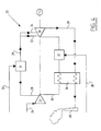
- FIG. 1 shows a system 1 for generating energy.
- the system 1 comprises a compressor unit 2 driven via a shaft 3 by a gas expansion turbine 4, which also drives a generator 5.
- the compressor unit 2 is provided with a (medium) air inlet 6 and an outlet 7 for compressed air.
- atomising means 8 are included for atomising evaporation agent, in this case water is supplied via water supply 9, into the air.
- the atomising means 8 comprise a casing containing a ring through which the air flows that is to be compressed. This ring contains a large number of (known) flash atomisation units spaced over the circumference at short distances from each other, each connected to the water supply 9.
- the flash atomisation units are constructed as swirl atomisers (see FIG.
- the compressed and heated gas After passing though a recuperator 10, the compressed and heated gas is brought, via outlet 7, into the combustion unit 11, to which fuel is fed via the fuel inlet.
- the flue gas is cleaned in unit 13, whereby the ashes are removed via outlet 14.
- the cleaned flue gas drives gas turbine 4. After passing the gas turbine, the gas passes the recuperator 10 and a heat exchanger 16 via line 15 and leaves the system 1 via the stack 17.
- the dried biomass originating from the heat exchanger 16 is pressurised in unit 18.
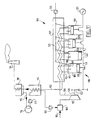
- FIG. 2 shows a similar system 20, for the generating of energy. Identical units are indicated by identical reference numbers.
- the evaporation agent (water) is supplied via water supply 9 prior and to the various compression stages of the compressor unit 2.
- the compressor unit 2 comprises a number of atomising means, each mounted with flash atomisation units.
- quasi-isothermal cooling is obtained.
- the gas that leaving gas turbine 4 via line 15 is removed via line 22.
- FIG. 3 shows a system 23 for compression for air separation.
- the air supplied via inlet 6 is pressurised.
- the air is cooled with water that is added to the atomising means 8, of which at least one contains a flash atomisation unit, via line 9.
- the pressurised air is supplied to the conventional air separator 26.
- atomising the, via a flash atomisation unit by flash atomisation in the air supplied via inlet 6.
- the air (29 kg/s) is compressed quasi-isothermally under flash atomisation of water (100 bar at 200°C).
- the air is heated from 15°C to 83°C. It is subsequently cooled to 25°C.
- the compression work is 5.3 MW.
- the cooling capacity is 6.9 MW. If adiabatic compression was applied (5 bar at 200°C), followed by cooling to 25°C, the compression work is 5.6 MW and the cooling capacity 5.9 MW.
- the energy consumption is reduced with 5.5%.
- the capacity of the compressor 24 increases by approximately 10%.
- the cooling capacity increases notably, as a result of the presence of water in the air and the fact that the increased capacity is caused by condensation of the water.
- the state of the art uses multi-stage compressors with intermediate intercoolers.
- oxygen 32 kg/s
- the oxygen is adiabatically compressed in a first compressor stage to 4 bar (temperature 175°C) and subsequently cooled down to 40 °C, whereby the pressure is reduced to 3.8 bar.
- the compression work is 4.7 MW and the cooling capacity 4 MW.
- the oxygen is compressed to 8 bar (at 214°C) and subsequently cooled to 25 °C.
- the compression work is 5.8 MW and the cooling capacity 5.5 MW.
- the total amount of compressor energy is 10.5 MW and the total cooling capacity 9.5 MW.
- FIG. 4 shows a system 25 for generating energy.
- System 25 comprises a compressor 27 mounted with an air inlet 26, and an outlet 28 for compressed air, which connects to the inlet 29 for the cooling air of turbine 30.
- the air inlet 29 is mounted with a flash atomisation unit 31, in which evaporation agent - water, in this instance - supplied via line 32 is sprayed in the compressed air and supplied to turbine 30 via two inlets 33 and 34.
- evaporation agent - water in this instance - supplied via line 32 is sprayed in the compressed air and supplied to turbine 30 via two inlets 33 and 34.
- the existing rotor air coolers and optionally the booster compressor may be reduced in number or size or replaced by the flash atomisation unit described.
- compressed air is also supplied to the combustion unit 37, via the outlet 35 and the heat exchanger 36.
- Fuel is supplied to the combustion unit 37 via line 38.
- An outlet 39 for exhaust from the turbine also passes the heat exchanger 36 and is carried away via stack 40.
- the capacity of the gas turbine may be increased by applying the flash atomisation unit, e.g. from 58.7 MW to 60.8 MW or even 61.3 MW (in the latter instance the booster compressor is shut down as well).
- the flash atomisation unit e.g. from 58.7 MW to 60.8 MW or even 61.3 MW (in the latter instance the booster compressor is shut down as well).
- FIG. 5 shows a diesel engine 41, mounted with a turbocharger 42. Via inlet 43 diesel oil is supplied to six cylinders 44, to which the inlets for compressed air are connected as well. The air compression takes place in a compressor 46, which is connected to the main inlet and mounted with an air inlet 47. Water supplied via line 48 is brought under pressure by pump 50 and is heated in heat exchanger 49 before being supplied to the flash atomisation unit 51, by which means very finely distributed water droplets are sprayed into compressor 46.
- the exhaust of the diesel engine 41 is carried off via line 52 and passes the turbine 53, the heat exchanger 49 and the valve 54 and exits the system via the stack 56, By using the flash atomisation units 51, cooler and moister compressed air is supplied to the cylinders of diesel engine 41, thus reducing the NO 2 emission.
- flash atomisation units 57 may also be utilised in each cylinder 44 for the atomisation of diesel oil.
- the diesel oil is supplied via line 43 and heated up by passing it via the heat exchanger 58 and if necessary by exchanging heat with the cylinder.
- the diesel oil has to be brought at such temperature as to enable the flash atomisation to take place at an accepted cylinder pressure, e.g. approximately 40 bar.
- an accepted cylinder pressure e.g. approximately 40 bar.
- the injection pressure may be reduced from approximately 1000 bar or more to e.g. 200 bar.
- Fuels like diesel oil have a boiling range. By temperatures of 350 °C, a significant flash effect will already occur for diesel oil. This may be lower for kerosene/gasoline (250/150 °C) and higher for slow speed ship diesel engines - up to 400 °C. Because the combustion of much smaller droplets is much more efficient, a more homogeneous combustion will take place, which results in a lower emission of soot.
- FIG. 7 shows a swirl atomiser 59, as known in the state of the art.
- the evaporation agent 61 is tangentially supplied to a swirl chamber 63 via an inlet 62.
- the evaporation agent attains a swirling movement 64 and leaves swirl chamber 63 via outlet 65.
- the swirling evaporation agent enters the space in which gaseous medium is present in the shape of a cone.
- the thickness of the layer of evaporation agent is reduced and ends up in very tiny droplets as the result of fragmentation. It may clearly be observed that the thickness of the layer of evaporation agent is less than the diameter of the outlet passage 65 of the swirl chamber 63. Because of the smaller size and relatively simple construction of the swirl atomiser 59, large numbers of such swirl atomisers may be applied for the flash atomisation of the liquid evaporation agent in the gaseous medium being or to be compressed.
- FIG. 8 shows a system 66 for generating energy.
- This system 66 comprises a compressor 67, connected to a turbine 69 by a shaft 68.
- Turbine 69 drives a generator 70.
- From a vessel 71 water at 15° C is pumped via a heat exchanger 73 by a pump 71.
- heat exchanger 73 the water is heated to 140-250° C by exchanging heat with the exhaust 74 of turbine 69.
- This warm and pressurised water is supplied to the flash atomisation unit 75, in which the water is atomised in air 76 of 15°C.
- the compressed air is supplied to a combustion unit 77, after which the exhaust gases are supplied to turbine 69 via the line 78.
- FIG. 9 shows a system 79 for generating energy.
- water 80 is supplied to the vessel 71 but carbon dioxide 81 as well.
- the water in the vessel 71 is saturated with carbon dioxide.
- This water is supplied under pressure to the flash atomisation unit 75 by means of pump 72 in order to cool the air 76 by generating very small water droplets.
- the moistened air is subsequently compressed in the compressor 67 while water droplets are evaporated.
- the exhaust is carried off via the exhaust outlet 82 via turbine 69 which drives the generator 70.
- FIG. 10 shows another system 83 for generating energy according to the invention, in accordance with the so-called TOPHAT principle.
- Air 85 is moistened and cooled in a flash atomisation unit 84 by means of water 86 supplied by means of flash atomisation.
- the air is supplied to a compressor 87 connected by a shaft 88 to a gas turbine 89 which drives a generator 90.
- the cool, compressed air passes a heat exchanger 92 via a line 91 and is supplied to the combustion unit 93, to which fuel is supplied via the line 94.
- the exhaust of gas turbine 89 passes the heat exchanger 92 via line 95 to be brought in heat exchanging contact with the cool, compressed air from the compressor 87.
- the exhaust passes a heat exchanger 97 and the condenser 98 on its way to the stack 99.
- water is condensed from the exhaust and pumped under pressure by pump 99 to the heat exchanger 97, after which the water 86, now under pressure and at the right temperature, reaches the flash atomisation unit 84. If necessary, water may be added to the condense water from the condenser 98 via line 100.
- FIG. 11 finally, shows a system 101 according to the invention for generating energy in accordance with the TOPHACE principle.
- Water at 140-250°C and 150 bar is pumped by pump 102 to a flash atomisation unit 103 to which air is supplied via line 104 (at 15°C). From the flash atomisation unit 103 the air reaches a compressor 105 which works with an efficiency of 0.8.
- the compressed air (now 140°C) is supplied via line 106 to a heat exchanger 107 to exchange heat with the exhaust gases of a combustion engine 108.
- the combustion engine comprises four cylinders 109 from which an air inlet 110 connects to the line 106 via a valve 111. From each of the cylinders 109 an exhaust pipe 112 passes the heat exchanger 107 and is led via a heat exchanger 114 via the line 113 and ends up via the condenser 98 in the stack 99.
- condenser 98 condense 115 is formed which after passing a water purifier 116 and after being brought under pressure by a pump 123 is added to the pump 102 via the heat exchanger 114.
- Fuel is supplied to each of the cylinders by the pump 124 via line 125 and the valves (not shown).
- the air is heated from 140°C to 377°C, whereas the exhaust from the cylinders 109 is cooled down from 465° C to 210°C.
- the air is supplied to the cylinders 108 and atomised fuel is injected.
- the cylinders 109 are also mounted with an ignitor 117 for igniting the mixture in each of the cylinders 109.
- the cylinders 109 are all mounted with a piston 118 connected to a shaft 119 which in turn is connected to the shaft 120 of the compressor 105 at one end and with the generator 121 on the other, via a 1:5 gear assembly 122.
- system 101 provides a power of 226 kW at 64% efficiency.
- a known device according to the Atkinson principle provides power of only 170 kW at 48% efficiency.
Landscapes
- Engineering & Computer Science (AREA)
- Mechanical Engineering (AREA)
- General Engineering & Computer Science (AREA)
- Chemical & Material Sciences (AREA)
- Combustion & Propulsion (AREA)
- Thermal Sciences (AREA)
- Physics & Mathematics (AREA)
- Health & Medical Sciences (AREA)
- Public Health (AREA)
- Water Supply & Treatment (AREA)
- Engine Equipment That Uses Special Cycles (AREA)
- Vaporization, Distillation, Condensation, Sublimation, And Cold Traps (AREA)
- Separation By Low-Temperature Treatments (AREA)
- Processing Of Solid Wastes (AREA)
Priority Applications (1)
| Application Number | Priority Date | Filing Date | Title |
|---|---|---|---|
| DK99929945T DK1007832T3 (da) | 1998-06-24 | 1999-06-18 | Apparat til komprimering af et gasformigt medium og systemer, som omfatter et sådant apparat |
Applications Claiming Priority (5)
| Application Number | Priority Date | Filing Date | Title |
|---|---|---|---|
| NL1009484 | 1998-06-24 | ||
| NL1009484A NL1009484C2 (nl) | 1998-06-24 | 1998-06-24 | Inrichting voor het comprimeren van een gasvormig medium en systemen die een dergelijke inrichting omvatten. |
| NL1011383 | 1999-02-24 | ||
| NL1011383A NL1011383C2 (nl) | 1998-06-24 | 1999-02-24 | Inrichting voor het comprimeren van een gasvormig medium en systemen die een dergelijke inrichting omvatten. |
| PCT/NL1999/000380 WO1999067519A1 (en) | 1998-06-24 | 1999-06-18 | Device for compressing a gaseous medium and systems comprising such device |
Publications (2)
| Publication Number | Publication Date |
|---|---|
| EP1007832A1 EP1007832A1 (en) | 2000-06-14 |
| EP1007832B1 true EP1007832B1 (en) | 2004-09-01 |
Family
ID=26642832
Family Applications (1)
| Application Number | Title | Priority Date | Filing Date |
|---|---|---|---|
| EP99929945A Expired - Lifetime EP1007832B1 (en) | 1998-06-24 | 1999-06-18 | Device for compressing a gaseous medium and systems comprising such device |
Country Status (13)
| Country | Link |
|---|---|
| US (1) | US6453659B1 (da) |
| EP (1) | EP1007832B1 (da) |
| JP (1) | JP4368526B2 (da) |
| KR (1) | KR100593854B1 (da) |
| AT (1) | ATE275238T1 (da) |
| AU (1) | AU745993B2 (da) |
| CA (1) | CA2301036C (da) |
| DE (1) | DE69919821T2 (da) |
| DK (1) | DK1007832T3 (da) |
| ES (1) | ES2223175T3 (da) |
| NL (1) | NL1011383C2 (da) |
| PT (1) | PT1007832E (da) |
| WO (1) | WO1999067519A1 (da) |
Cited By (1)
| Publication number | Priority date | Publication date | Assignee | Title |
|---|---|---|---|---|
| CN103080502A (zh) * | 2010-08-27 | 2013-05-01 | 株式会社日立制作所 | 利用太阳热燃气轮机系统 |
Families Citing this family (65)
| Publication number | Priority date | Publication date | Assignee | Title |
|---|---|---|---|---|
| WO1998048159A1 (en) * | 1997-04-22 | 1998-10-29 | Hitachi, Ltd. | Gas turbine equipment |
| US6470667B1 (en) | 1998-07-24 | 2002-10-29 | General Electric Company | Methods and apparatus for water injection in a turbine engine |
| US6467252B1 (en) * | 1998-07-24 | 2002-10-22 | General Electric Company | Nozzles for water injection in a turbine engine |
| US6484508B2 (en) | 1998-07-24 | 2002-11-26 | General Electric Company | Methods for operating gas turbine engines |
| GB2382848A (en) | 2001-12-06 | 2003-06-11 | Alstom | Gas turbine wet compression |
| GB2382847A (en) | 2001-12-06 | 2003-06-11 | Alstom | Gas turbine wet compression |
| AU2003205939A1 (en) * | 2002-02-19 | 2003-09-09 | Alstom Technology Ltd | Turboblower and method for operating such a turboblower |
| DE10207197A1 (de) * | 2002-02-21 | 2003-09-04 | Alstom Switzerland Ltd | Hochdruckeinspritzdüse, insbesondere für den Einsatz als Explosionszerstäuber |
| AU2003257385A1 (en) * | 2002-07-14 | 2004-02-09 | Rerum Cognitio Gesellschaft Fur Marktintegration Deutscher Innovation Und Forschungsprodukte Mbh | Method for compressing the working fluid during a water/steam combination process |
| US20040050055A1 (en) * | 2002-09-13 | 2004-03-18 | Spraying Systems, Co. | Gas turbine power augmenting spray nozzle assembly |
| DE10256193A1 (de) | 2002-12-02 | 2004-06-09 | Alstom Technology Ltd | Verfahren zur Steuerung der Flüssigkeitseinspritzung in einen Zuströmkanal einer Kraft- oder Arbeitsmaschine |
| KR100900401B1 (ko) * | 2002-12-24 | 2009-06-02 | 재단법인 포항산업과학연구원 | 배열 발전시스템 |
| US6681748B1 (en) * | 2003-03-17 | 2004-01-27 | Hsiang-Lan Chiu | Secondary cooling system for a vehicular intake booster |
| US20050056313A1 (en) * | 2003-09-12 | 2005-03-17 | Hagen David L. | Method and apparatus for mixing fluids |
| EP1682750B1 (de) | 2003-10-30 | 2012-11-28 | Alstom Technology Ltd | Kraftwerksanlage |
| EP1704313B1 (de) | 2003-10-30 | 2016-03-30 | Alstom Technology Ltd | Verfahren zum betrieb einer kraftwerksanlage |
| US7033135B2 (en) * | 2003-11-10 | 2006-04-25 | General Electric Company | Method and apparatus for distributing fluid into a turbomachine |
| DE10357711A1 (de) * | 2003-12-09 | 2005-07-14 | Abb Turbo Systems Ag | Kühlungsverfahren |
| EP1557539A1 (de) * | 2004-01-21 | 2005-07-27 | Siemens Aktiengesellschaft | Verfahren und Anordnung zur Leistungs- und Wirkungsgraderhöhung in einer Gasturbinenanlage, sowie Gasturbinenanlage |
| DE102004028224A1 (de) * | 2004-06-09 | 2006-01-05 | Man B & W Diesel Ag | Verfahren zum Betreiben eines Turboladers sowie Turbolader |
| US7093446B2 (en) * | 2004-09-15 | 2006-08-22 | General Electric Company | Gas turbine engine having improved core system |
| US7096674B2 (en) * | 2004-09-15 | 2006-08-29 | General Electric Company | High thrust gas turbine engine with improved core system |
| CA2606756C (en) * | 2005-05-02 | 2013-10-08 | Vast Power Portfolio, Llc | Wet compression apparatus and method |
| DE102005032556B4 (de) * | 2005-07-11 | 2007-04-12 | Atlas Copco Energas Gmbh | Anlage und Verfahren zur Nutzung eines Gases |
| JP2008175149A (ja) * | 2007-01-19 | 2008-07-31 | Hitachi Ltd | 圧縮機の吸気噴霧装置 |
| DE102007015309B4 (de) | 2007-03-27 | 2023-01-05 | Ansaldo Energia Switzerland AG | Betriebsverfahren für eine Turbogruppe |
| EP1990578A1 (de) * | 2007-05-08 | 2008-11-12 | ALSTOM Technology Ltd | Gasturbine mit Wassereinspritzung |
| US8677744B2 (en) | 2008-04-09 | 2014-03-25 | SustaioX, Inc. | Fluid circulation in energy storage and recovery systems |
| US8250863B2 (en) | 2008-04-09 | 2012-08-28 | Sustainx, Inc. | Heat exchange with compressed gas in energy-storage systems |
| EP2280841A2 (en) | 2008-04-09 | 2011-02-09 | Sustainx, Inc. | Systems and methods for energy storage and recovery using compressed gas |
| US8479505B2 (en) | 2008-04-09 | 2013-07-09 | Sustainx, Inc. | Systems and methods for reducing dead volume in compressed-gas energy storage systems |
| US8037678B2 (en) | 2009-09-11 | 2011-10-18 | Sustainx, Inc. | Energy storage and generation systems and methods using coupled cylinder assemblies |
| US8225606B2 (en) | 2008-04-09 | 2012-07-24 | Sustainx, Inc. | Systems and methods for energy storage and recovery using rapid isothermal gas expansion and compression |
| US8359856B2 (en) | 2008-04-09 | 2013-01-29 | Sustainx Inc. | Systems and methods for efficient pumping of high-pressure fluids for energy storage and recovery |
| US8474255B2 (en) * | 2008-04-09 | 2013-07-02 | Sustainx, Inc. | Forming liquid sprays in compressed-gas energy storage systems for effective heat exchange |
| US20100006073A1 (en) * | 2008-07-10 | 2010-01-14 | Jayant Jatkar | Increasing effeciency of internal combustion engines to increase mileage of vehicles |
| US8038952B2 (en) * | 2008-08-28 | 2011-10-18 | General Electric Company | Surface treatments and coatings for flash atomization |
| KR101036592B1 (ko) * | 2008-11-28 | 2011-05-24 | 세메스 주식회사 | 처리액 공급 유닛과, 이를 이용한 기판 처리 장치 |
| US8104274B2 (en) | 2009-06-04 | 2012-01-31 | Sustainx, Inc. | Increased power in compressed-gas energy storage and recovery |
| US8857383B2 (en) * | 2009-06-30 | 2014-10-14 | Cummins Power Generation Ip, Inc. | Apparatus, systems, and methods to address evaporative cooling and wet compression for engine thermal management |
| US8171728B2 (en) | 2010-04-08 | 2012-05-08 | Sustainx, Inc. | High-efficiency liquid heat exchange in compressed-gas energy storage systems |
| US8191362B2 (en) | 2010-04-08 | 2012-06-05 | Sustainx, Inc. | Systems and methods for reducing dead volume in compressed-gas energy storage systems |
| US8495872B2 (en) | 2010-08-20 | 2013-07-30 | Sustainx, Inc. | Energy storage and recovery utilizing low-pressure thermal conditioning for heat exchange with high-pressure gas |
| WO2012042628A1 (ja) * | 2010-09-30 | 2012-04-05 | 株式会社日立製作所 | ガスタービン発電装置、ガスタービン発電システムおよびその制御方法 |
| JP5422057B2 (ja) * | 2010-09-30 | 2014-02-19 | 株式会社日立製作所 | ガスタービンシステム及びその制御方法 |
| US8978386B2 (en) * | 2010-09-30 | 2015-03-17 | Mitsubishi Hitachi Power Systems, Ltd. | Gas turbine system, control device for gas turbine system, and control method for gas turbine system |
| CN103080503B (zh) * | 2010-09-30 | 2016-06-08 | 三菱日立电力系统株式会社 | 太阳热利用联合循环发电站 |
| JPWO2012120555A1 (ja) * | 2011-03-07 | 2014-07-07 | 株式会社日立製作所 | 太陽熱利用ガスタービンシステム |
| JP2014522460A (ja) | 2011-05-17 | 2014-09-04 | サステインエックス, インコーポレイテッド | 圧縮空気エネルギー貯蔵システムにおける効率的二相熱移送のためのシステムおよび方法 |
| CH705181A1 (de) | 2011-06-16 | 2012-12-31 | Alstom Technology Ltd | Verfahren zum Kühlen einer Gasturbinenanlage sowie Gasturbinenanlage zur Durchführung des Verfahrens. |
| US10222120B2 (en) | 2011-09-20 | 2019-03-05 | Linde Aktiengesellschaft | Method and device for generating two purified partial air streams |
| US20130091836A1 (en) | 2011-10-14 | 2013-04-18 | Sustainx, Inc. | Dead-volume management in compressed-gas energy storage and recovery systems |
| FR2984474A1 (fr) * | 2011-12-16 | 2013-06-21 | Air Liquide | Procede et appareil de separation d'air par distillation cryogenique |
| US20130199192A1 (en) * | 2012-02-07 | 2013-08-08 | General Electric Company | System and method for gas turbine nox emission improvement |
| US20150033760A1 (en) * | 2012-02-24 | 2015-02-05 | Mitsubishi Httachi Power Systems, Ltd. | Solar Assisted Gas Turbine System |
| JP2014029118A (ja) | 2012-07-31 | 2014-02-13 | Hitachi Ltd | 噴霧装置 |
| RU2529289C1 (ru) * | 2013-03-12 | 2014-09-27 | Федеральное государственное бюджетное образовательное учреждение высшего профессионального образования "Казанский государственный энергетический университет" (ФГБОУ ВПО "КГЭУ") | Способ повышения эффективности работы осевого многоступенчатого компрессора |
| US20140182561A1 (en) * | 2013-09-25 | 2014-07-03 | Eghosa Gregory Ibizugbe, JR. | Onboard CNG/CFG Vehicle Refueling and Storage Systems and Methods |
| DE102013223784A1 (de) * | 2013-11-21 | 2015-05-21 | Siemens Aktiengesellschaft | Verfahren und Vorrichtung zur Handhabung von Gas |
| JP6303700B2 (ja) * | 2014-03-28 | 2018-04-04 | 東京電力ホールディングス株式会社 | ガスタービンプラント及びガスタービンプラントの吸気冷却方法 |
| US9932856B2 (en) * | 2014-11-22 | 2018-04-03 | General Electric Company | Cooling apparatus for turbomachinery with method of installation |
| JP2018509559A (ja) * | 2015-03-26 | 2018-04-05 | エクソンモービル アップストリーム リサーチ カンパニー | 圧縮機システムを制御する方法及び圧縮機システム |
| DE102016200678A1 (de) * | 2016-01-20 | 2017-07-20 | Siemens Aktiengesellschaft | Gasturbine mit Wet-Compression-Einrichtung zur Einbringung einer tensidischen Flüssigkeitsmischung |
| JP7085198B2 (ja) * | 2018-06-25 | 2022-06-16 | 株式会社いけうち | 吸気冷却装置および吸気冷却方法 |
| US11193421B2 (en) | 2019-06-07 | 2021-12-07 | Saudi Arabian Oil Company | Cold recycle process for gas turbine inlet air cooling |
Family Cites Families (21)
| Publication number | Priority date | Publication date | Assignee | Title |
|---|---|---|---|---|
| NL39361C (da) * | 1900-01-01 | |||
| GB384667A (en) * | 1930-06-14 | 1932-12-05 | Homestead Valve Mfg Co | Improvements in or relating to a method of and apparatus for partially vaporizing and |
| US3885390A (en) * | 1974-02-12 | 1975-05-27 | Glen R Evans | Internal combustion and steam pressure generator with powered expansion engine |
| US3973395A (en) * | 1974-12-18 | 1976-08-10 | United Technologies Corporation | Low emission combustion chamber |
| US3964263A (en) * | 1974-12-31 | 1976-06-22 | Tibbs Robert C | Six cycle combustion and fluid vaporization engine |
| FR2404737A1 (fr) * | 1977-09-28 | 1979-04-27 | Uniscrew Ltd | Machine motrice a injection d'eau |
| US4189914A (en) * | 1978-06-19 | 1980-02-26 | The United States Of America As Represented By The Administrator Of The National Aeronautics And Space Administration | Supercritical fuel injection system |
| DE2925091A1 (de) * | 1979-06-21 | 1981-01-08 | Vinko Dipl Ing Mucic | Verbrennungskraftmaschine |
| DE2931178A1 (de) * | 1979-08-01 | 1981-02-19 | Maschf Augsburg Nuernberg Ag | Gasturbinen-energiewandlungs-verfahren und vorrichtung zu seiner durchfuehrung |
| US4383645A (en) * | 1980-12-15 | 1983-05-17 | Allied Corporation | Vapor sprayer and process for providing a volatile fluid as a vapor spray |
| US4478553A (en) * | 1982-03-29 | 1984-10-23 | Mechanical Technology Incorporated | Isothermal compression |
| JPS59160032A (ja) | 1983-03-01 | 1984-09-10 | Agency Of Ind Science & Technol | ガスタ−ビン |
| US4991391A (en) | 1989-01-27 | 1991-02-12 | Westinghouse Electric Corp. | System for cooling in a gas turbine |
| DE4114678A1 (de) * | 1991-05-06 | 1992-11-12 | Hans Christoph Dr Ing Pohl | Quasi-isotherme verdichtung kompressor mit einspritzung |
| US5282726A (en) * | 1991-06-21 | 1994-02-01 | Praxair Technology, Inc. | Compressor supercharger with evaporative cooler |
| AU657189B2 (en) * | 1992-01-23 | 1995-03-02 | Air Products And Chemicals Inc. | Internal combustion engine with cooling of intake air using refrigeration of liquefied fuel gas |
| DE4237664A1 (de) * | 1992-11-07 | 1994-05-11 | Asea Brown Boveri | Verfahren zum Betrieb eines Turboverdichters |
| US5622044A (en) * | 1992-11-09 | 1997-04-22 | Ormat Industries Ltd. | Apparatus for augmenting power produced from gas turbines |
| US5669217A (en) * | 1995-09-25 | 1997-09-23 | Anderson; J. Hilbert | Method and apparatus for intercooling gas turbines |
| JP2877098B2 (ja) * | 1995-12-28 | 1999-03-31 | 株式会社日立製作所 | ガスタービン,コンバインドサイクルプラント及び圧縮機 |
| EP0821137A1 (en) | 1996-07-22 | 1998-01-28 | N.V. Kema | System for power generation |
-
1999
- 1999-02-24 NL NL1011383A patent/NL1011383C2/nl not_active IP Right Cessation
- 1999-06-18 KR KR1020007001857A patent/KR100593854B1/ko not_active Expired - Fee Related
- 1999-06-18 DK DK99929945T patent/DK1007832T3/da active
- 1999-06-18 JP JP2000556145A patent/JP4368526B2/ja not_active Expired - Fee Related
- 1999-06-18 AU AU46577/99A patent/AU745993B2/en not_active Ceased
- 1999-06-18 CA CA002301036A patent/CA2301036C/en not_active Expired - Fee Related
- 1999-06-18 WO PCT/NL1999/000380 patent/WO1999067519A1/en not_active Ceased
- 1999-06-18 EP EP99929945A patent/EP1007832B1/en not_active Expired - Lifetime
- 1999-06-18 ES ES99929945T patent/ES2223175T3/es not_active Expired - Lifetime
- 1999-06-18 US US09/486,133 patent/US6453659B1/en not_active Expired - Lifetime
- 1999-06-18 PT PT99929945T patent/PT1007832E/pt unknown
- 1999-06-18 AT AT99929945T patent/ATE275238T1/de active
- 1999-06-18 DE DE69919821T patent/DE69919821T2/de not_active Expired - Lifetime
Cited By (2)
| Publication number | Priority date | Publication date | Assignee | Title |
|---|---|---|---|---|
| CN103080502A (zh) * | 2010-08-27 | 2013-05-01 | 株式会社日立制作所 | 利用太阳热燃气轮机系统 |
| CN103080502B (zh) * | 2010-08-27 | 2016-03-23 | 三菱日立电力系统株式会社 | 利用太阳热燃气轮机系统 |
Also Published As
| Publication number | Publication date |
|---|---|
| WO1999067519A1 (en) | 1999-12-29 |
| AU745993B2 (en) | 2002-04-11 |
| NL1011383C2 (nl) | 1999-12-27 |
| KR100593854B1 (ko) | 2006-06-28 |
| EP1007832A1 (en) | 2000-06-14 |
| KR20010023228A (ko) | 2001-03-26 |
| JP4368526B2 (ja) | 2009-11-18 |
| PT1007832E (pt) | 2004-12-31 |
| AU4657799A (en) | 2000-01-10 |
| DE69919821D1 (de) | 2004-10-07 |
| CA2301036A1 (en) | 1999-12-29 |
| US6453659B1 (en) | 2002-09-24 |
| DE69919821T2 (de) | 2005-09-29 |
| ES2223175T3 (es) | 2005-02-16 |
| CA2301036C (en) | 2008-04-22 |
| DK1007832T3 (da) | 2005-01-10 |
| JP2002519558A (ja) | 2002-07-02 |
| ATE275238T1 (de) | 2004-09-15 |
Similar Documents
| Publication | Publication Date | Title |
|---|---|---|
| EP1007832B1 (en) | Device for compressing a gaseous medium and systems comprising such device | |
| US6688108B1 (en) | Power generating system comprising a combustion unit that includes an explosion atomizing unit for combusting a liquid fuel | |
| CA2088947C (en) | Hydrogen fuelled gas turbine | |
| US5718194A (en) | In-cylinder water injection engine | |
| US6263661B1 (en) | System for power generation | |
| US7089743B2 (en) | Method for operating a power plant by means of a CO2 process | |
| US4949544A (en) | Series intercooler | |
| US20090158739A1 (en) | Gas turbine systems and methods employing a vaporizable liquid delivery device | |
| US6845738B2 (en) | Method for operating an internal combustion engine | |
| JPH11324710A (ja) | ガスタービン発電プラント | |
| EP1155225B1 (en) | Combustion unit for combusting a liquid fuel and a power generating system comprising such combustion unit | |
| RU2232912C2 (ru) | Способ работы и устройство поршневого двигателя внутреннего сгорания с комплексной системой глубокой утилизации теплоты и снижения вредных выбросов в атмосферу | |
| RU2232913C2 (ru) | Способ работы и устройство поршневого двигателя внутреннего сгорания с газопаровым рабочим телом | |
| GB2086483A (en) | Plant vaporizing a secondary fluid using heat of compression of a primary fluid. | |
| AU2002300172B2 (en) | Device for compressing a gaseous medium and systems comprising such device | |
| US20130167532A1 (en) | Power generator and related engine systems | |
| CN1201865A (zh) | 一种内燃蒸气发动机 | |
| US20140216045A1 (en) | Gas turbine with improved power output | |
| NL1012936C2 (nl) | Verbrandingseenheid voor het verbranden van een vloeibare brandstof en een energie-opwekkingssysteem dat een dergelijke verbrandingseenheid omvat. | |
| MXPA97001886A (es) | Motor de inyeccion de agua en el cilindro |
Legal Events
| Date | Code | Title | Description |
|---|---|---|---|
| PUAI | Public reference made under article 153(3) epc to a published international application that has entered the european phase |
Free format text: ORIGINAL CODE: 0009012 |
|
| 17P | Request for examination filed |
Effective date: 20000221 |
|
| AK | Designated contracting states |
Kind code of ref document: A1 Designated state(s): AT BE CH CY DE DK ES FI FR GB GR IE IT LI LU MC NL PT SE |
|
| GRAP | Despatch of communication of intention to grant a patent |
Free format text: ORIGINAL CODE: EPIDOSNIGR1 |
|
| GRAS | Grant fee paid |
Free format text: ORIGINAL CODE: EPIDOSNIGR3 |
|
| GRAA | (expected) grant |
Free format text: ORIGINAL CODE: 0009210 |
|
| AK | Designated contracting states |
Kind code of ref document: B1 Designated state(s): AT BE CH CY DE DK ES FI FR GB GR IE IT LI LU MC NL PT SE |
|
| PG25 | Lapsed in a contracting state [announced via postgrant information from national office to epo] |
Ref country code: FI Free format text: LAPSE BECAUSE OF FAILURE TO SUBMIT A TRANSLATION OF THE DESCRIPTION OR TO PAY THE FEE WITHIN THE PRESCRIBED TIME-LIMIT Effective date: 20040901 |
|
| REG | Reference to a national code |
Ref country code: GB Ref legal event code: FG4D |
|
| REG | Reference to a national code |
Ref country code: CH Ref legal event code: NV Representative=s name: ARNOLD & SIEDSMA AG Ref country code: CH Ref legal event code: EP |
|
| REG | Reference to a national code |
Ref country code: SE Ref legal event code: TRGR |
|
| REG | Reference to a national code |
Ref country code: IE Ref legal event code: FG4D |
|
| REF | Corresponds to: |
Ref document number: 69919821 Country of ref document: DE Date of ref document: 20041007 Kind code of ref document: P |
|
| REG | Reference to a national code |
Ref country code: GR Ref legal event code: EP Ref document number: 20040403805 Country of ref document: GR |
|
| REG | Reference to a national code |
Ref country code: PT Ref legal event code: SC4A Free format text: AVAILABILITY OF NATIONAL TRANSLATION Effective date: 20041104 |
|
| REG | Reference to a national code |
Ref country code: ES Ref legal event code: FG2A Ref document number: 2223175 Country of ref document: ES Kind code of ref document: T3 |
|
| REG | Reference to a national code |
Ref country code: GB Ref legal event code: 732E |
|
| PG25 | Lapsed in a contracting state [announced via postgrant information from national office to epo] |
Ref country code: LU Free format text: LAPSE BECAUSE OF NON-PAYMENT OF DUE FEES Effective date: 20050618 Ref country code: CY Free format text: LAPSE BECAUSE OF FAILURE TO SUBMIT A TRANSLATION OF THE DESCRIPTION OR TO PAY THE FEE WITHIN THE PRESCRIBED TIME-LIMIT Effective date: 20050618 |
|
| PG25 | Lapsed in a contracting state [announced via postgrant information from national office to epo] |
Ref country code: MC Free format text: LAPSE BECAUSE OF NON-PAYMENT OF DUE FEES Effective date: 20050630 |
|
| PLBE | No opposition filed within time limit |
Free format text: ORIGINAL CODE: 0009261 |
|
| STAA | Information on the status of an ep patent application or granted ep patent |
Free format text: STATUS: NO OPPOSITION FILED WITHIN TIME LIMIT |
|
| RAP2 | Party data changed (patent owner data changed or rights of a patent transferred) |
Owner name: STORK THERMEQ B.V. |
|
| ET | Fr: translation filed | ||
| 26N | No opposition filed |
Effective date: 20050602 |
|
| NLT2 | Nl: modifications (of names), taken from the european patent patent bulletin |
Owner name: STORK THERMEQ B.V. Effective date: 20050713 |
|
| REG | Reference to a national code |
Ref country code: CH Ref legal event code: PUE Owner name: STORK THERMEQ B.V. Free format text: N.V. KEMA#UTRECHTSEWEG 310#6812 AR ARNHEM (NL) -TRANSFER TO- STORK THERMEQ B.V.#LANGELERMAATWEG 12#7553 JD HENGELO (NL) |
|
| NLS | Nl: assignments of ep-patents |
Owner name: STORK THERMEQ B.V. Effective date: 20051103 |
|
| REG | Reference to a national code |
Ref country code: FR Ref legal event code: TP |
|
| REG | Reference to a national code |
Ref country code: NL Ref legal event code: PLED Effective date: 20130220 |
|
| REG | Reference to a national code |
Ref country code: NL Ref legal event code: PLED Effective date: 20130708 |
|
| REG | Reference to a national code |
Ref country code: FR Ref legal event code: PLFP Year of fee payment: 17 |
|
| PGFP | Annual fee paid to national office [announced via postgrant information from national office to epo] |
Ref country code: SE Payment date: 20150626 Year of fee payment: 17 Ref country code: CH Payment date: 20150624 Year of fee payment: 17 Ref country code: DK Payment date: 20150630 Year of fee payment: 17 Ref country code: ES Payment date: 20150625 Year of fee payment: 17 Ref country code: PT Payment date: 20150526 Year of fee payment: 17 Ref country code: GB Payment date: 20150626 Year of fee payment: 17 |
|
| PGFP | Annual fee paid to national office [announced via postgrant information from national office to epo] |
Ref country code: IE Payment date: 20150625 Year of fee payment: 17 Ref country code: GR Payment date: 20150624 Year of fee payment: 17 Ref country code: BE Payment date: 20150624 Year of fee payment: 17 Ref country code: AT Payment date: 20150630 Year of fee payment: 17 |
|
| PGFP | Annual fee paid to national office [announced via postgrant information from national office to epo] |
Ref country code: NL Payment date: 20150630 Year of fee payment: 17 |
|
| PGFP | Annual fee paid to national office [announced via postgrant information from national office to epo] |
Ref country code: DE Payment date: 20150630 Year of fee payment: 17 |
|
| PGFP | Annual fee paid to national office [announced via postgrant information from national office to epo] |
Ref country code: FR Payment date: 20150630 Year of fee payment: 17 |
|
| REG | Reference to a national code |
Ref country code: NL Ref legal event code: RC Free format text: DETAILS LICENCE OR PLEDGE: PANDRECHT, GEVESTIGD, INDIENING PANDAKTE OP 13 NOVEMBER 2015 DOOR EXTER POLAK & CHARLOUIS B.V. TE RIJSWIJK. PANDGEVER IS STORK THERMEQ B.V. TE HENGELO. PANDHOUDER IS COOEPERATIEVE CENTRALE RAIFFEISEN-BOERENLEENBANK B.A. TE UTRECHT. ZIE VERDER DE AKTE. Name of requester: COOEPERATIEVE CENTRALE RAIFFEISEN-BOERENLEENBANK B Effective date: 20151013 |
|
| PGFP | Annual fee paid to national office [announced via postgrant information from national office to epo] |
Ref country code: IT Payment date: 20150626 Year of fee payment: 17 |
|
| PG25 | Lapsed in a contracting state [announced via postgrant information from national office to epo] |
Ref country code: BE Free format text: LAPSE BECAUSE OF NON-PAYMENT OF DUE FEES Effective date: 20160630 |
|
| REG | Reference to a national code |
Ref country code: DE Ref legal event code: R119 Ref document number: 69919821 Country of ref document: DE |
|
| REG | Reference to a national code |
Ref country code: DK Ref legal event code: EBP Effective date: 20160630 |
|
| REG | Reference to a national code |
Ref country code: CH Ref legal event code: PL Ref country code: SE Ref legal event code: EUG |
|
| REG | Reference to a national code |
Ref country code: NL Ref legal event code: MM Effective date: 20160701 |
|
| REG | Reference to a national code |
Ref country code: AT Ref legal event code: MM01 Ref document number: 275238 Country of ref document: AT Kind code of ref document: T Effective date: 20160618 |
|
| PG25 | Lapsed in a contracting state [announced via postgrant information from national office to epo] |
Ref country code: SE Free format text: LAPSE BECAUSE OF NON-PAYMENT OF DUE FEES Effective date: 20160619 Ref country code: PT Free format text: LAPSE BECAUSE OF NON-PAYMENT OF DUE FEES Effective date: 20161219 |
|
| GBPC | Gb: european patent ceased through non-payment of renewal fee |
Effective date: 20160618 |
|
| REG | Reference to a national code |
Ref country code: GR Ref legal event code: ML Ref document number: 20040403805 Country of ref document: GR Effective date: 20170109 |
|
| REG | Reference to a national code |
Ref country code: IE Ref legal event code: MM4A |
|
| REG | Reference to a national code |
Ref country code: FR Ref legal event code: ST Effective date: 20170228 |
|
| PG25 | Lapsed in a contracting state [announced via postgrant information from national office to epo] |
Ref country code: FR Free format text: LAPSE BECAUSE OF NON-PAYMENT OF DUE FEES Effective date: 20160630 Ref country code: DE Free format text: LAPSE BECAUSE OF NON-PAYMENT OF DUE FEES Effective date: 20170103 Ref country code: LI Free format text: LAPSE BECAUSE OF NON-PAYMENT OF DUE FEES Effective date: 20160630 Ref country code: GR Free format text: LAPSE BECAUSE OF NON-PAYMENT OF DUE FEES Effective date: 20170109 Ref country code: CH Free format text: LAPSE BECAUSE OF NON-PAYMENT OF DUE FEES Effective date: 20160630 |
|
| PG25 | Lapsed in a contracting state [announced via postgrant information from national office to epo] |
Ref country code: AT Free format text: LAPSE BECAUSE OF NON-PAYMENT OF DUE FEES Effective date: 20160618 Ref country code: IE Free format text: LAPSE BECAUSE OF NON-PAYMENT OF DUE FEES Effective date: 20160618 Ref country code: GB Free format text: LAPSE BECAUSE OF NON-PAYMENT OF DUE FEES Effective date: 20160618 Ref country code: NL Free format text: LAPSE BECAUSE OF NON-PAYMENT OF DUE FEES Effective date: 20160701 |
|
| PG25 | Lapsed in a contracting state [announced via postgrant information from national office to epo] |
Ref country code: IT Free format text: LAPSE BECAUSE OF NON-PAYMENT OF DUE FEES Effective date: 20160618 |
|
| PG25 | Lapsed in a contracting state [announced via postgrant information from national office to epo] |
Ref country code: DK Free format text: LAPSE BECAUSE OF NON-PAYMENT OF DUE FEES Effective date: 20160630 |
|
| PG25 | Lapsed in a contracting state [announced via postgrant information from national office to epo] |
Ref country code: ES Free format text: LAPSE BECAUSE OF NON-PAYMENT OF DUE FEES Effective date: 20160619 |
|
| REG | Reference to a national code |
Ref country code: ES Ref legal event code: FD2A Effective date: 20181126 |