EP1007846B1 - Reaktives polymergelbetägtigtes pumpsystem - Google Patents
Reaktives polymergelbetägtigtes pumpsystem Download PDFInfo
- Publication number
- EP1007846B1 EP1007846B1 EP98939946A EP98939946A EP1007846B1 EP 1007846 B1 EP1007846 B1 EP 1007846B1 EP 98939946 A EP98939946 A EP 98939946A EP 98939946 A EP98939946 A EP 98939946A EP 1007846 B1 EP1007846 B1 EP 1007846B1
- Authority
- EP
- European Patent Office
- Prior art keywords
- gel
- chamber
- pumping system
- volume
- fluid
- Prior art date
- Legal status (The legal status is an assumption and is not a legal conclusion. Google has not performed a legal analysis and makes no representation as to the accuracy of the status listed.)
- Expired - Lifetime
Links
- 238000005086 pumping Methods 0.000 title claims description 30
- 229920013730 reactive polymer Polymers 0.000 title claims description 6
- 239000012530 fluid Substances 0.000 claims description 33
- 239000004020 conductor Substances 0.000 claims description 11
- 230000005672 electromagnetic field Effects 0.000 claims description 6
- 230000003247 decreasing effect Effects 0.000 claims description 3
- 239000013528 metallic particle Substances 0.000 claims description 3
- 239000000203 mixture Substances 0.000 claims description 2
- QNILTEGFHQSKFF-UHFFFAOYSA-N n-propan-2-ylprop-2-enamide Chemical compound CC(C)NC(=O)C=C QNILTEGFHQSKFF-UHFFFAOYSA-N 0.000 claims description 2
- XLYOFNOQVPJJNP-UHFFFAOYSA-N water Substances O XLYOFNOQVPJJNP-UHFFFAOYSA-N 0.000 claims description 2
- 238000007599 discharging Methods 0.000 claims 2
- 239000003999 initiator Substances 0.000 claims 1
- 230000008961 swelling Effects 0.000 claims 1
- 230000000903 blocking effect Effects 0.000 description 4
- 230000008602 contraction Effects 0.000 description 4
- 230000005611 electricity Effects 0.000 description 4
- 238000001816 cooling Methods 0.000 description 2
- 238000010438 heat treatment Methods 0.000 description 2
- 239000007788 liquid Substances 0.000 description 2
- 238000010276 construction Methods 0.000 description 1
- 230000007613 environmental effect Effects 0.000 description 1
- 239000000463 material Substances 0.000 description 1
- 239000002184 metal Substances 0.000 description 1
- 239000003505 polymerization initiator Substances 0.000 description 1
- 230000000750 progressive effect Effects 0.000 description 1
- 229920000208 temperature-responsive polymer Polymers 0.000 description 1
Images
Classifications
-
- F—MECHANICAL ENGINEERING; LIGHTING; HEATING; WEAPONS; BLASTING
- F04—POSITIVE - DISPLACEMENT MACHINES FOR LIQUIDS; PUMPS FOR LIQUIDS OR ELASTIC FLUIDS
- F04B—POSITIVE-DISPLACEMENT MACHINES FOR LIQUIDS; PUMPS
- F04B43/00—Machines, pumps, or pumping installations having flexible working members
- F04B43/08—Machines, pumps, or pumping installations having flexible working members having tubular flexible members
- F04B43/09—Pumps having electric drive
-
- E—FIXED CONSTRUCTIONS
- E21—EARTH OR ROCK DRILLING; MINING
- E21B—EARTH OR ROCK DRILLING; OBTAINING OIL, GAS, WATER, SOLUBLE OR MELTABLE MATERIALS OR A SLURRY OF MINERALS FROM WELLS
- E21B43/00—Methods or apparatus for obtaining oil, gas, water, soluble or meltable materials or a slurry of minerals from wells
- E21B43/12—Methods or apparatus for controlling the flow of the obtained fluid to or in wells
- E21B43/121—Lifting well fluids
- E21B43/128—Adaptation of pump systems with down-hole electric drives
-
- F—MECHANICAL ENGINEERING; LIGHTING; HEATING; WEAPONS; BLASTING
- F04—POSITIVE - DISPLACEMENT MACHINES FOR LIQUIDS; PUMPS FOR LIQUIDS OR ELASTIC FLUIDS
- F04B—POSITIVE-DISPLACEMENT MACHINES FOR LIQUIDS; PUMPS
- F04B17/00—Pumps characterised by combination with, or adaptation to, specific driving engines or motors
Definitions
- This invention relates in general to a pumping system comprising a pump, particularly a submersible well pump.
- prior art well pumps there are a variety of prior art well pumps in use.
- One of the most popular types of prior art well pumps comprises a reciprocating rod system which is primarily used for low volume flow rates. If higher volume flow rates are required, electrical submersible pumps are more appropriate.
- Another type of prior art well pump is the progressive cavity pump which utilizes a rotating helical rod within an elastomeric sleeve to move fluids.
- US 5 288 214 refers to a micropump comprising a housing for defining a pump chamber, an inlet valve means disposed in an inlet flow passage connected to the pump chamber, an outlet valve means disposed in an outlet flow passage connected to the pump chamber, and an actuator for changing a volume of the pump chamber.
- the inlet valve means and the outlet valve means respectively comprise a valve body defining a valve chamber, a blocking means disposed in the valve chamber, and a deviating means for deviating resiliently the blocking valve means in a direction for closing a flow passage.
- the actuator is made of a thermo-responsive polymer gel material.
- the actuator is decreasing in volume when heated resulting in increasing the volume of and reducing the pressure within the pump chamber so as to draw the blocking means of the inlet valve means in a valve opening direction against an action of the deviating means of the inlet valve means to permit liquid to flow into the pump chamber through the inlet flow passage.
- the actuator is increasing in volume when cooled resulting in decreasing the volume of and increasing the pressure within the pump chamber so as to move the blocking means of the outlet valve means toward an opening direction against an action of the deviating means of the outlet valve means to permit liquid to discharge from the pump chamber through the outlet flow passage.
- a subsurface well system contains well bore fluid and a pumping system which is lowered into the well bore on a conduit.
- the pumping system is supplied with electrical power through an insulated conductor which extends from the surface.
- the pumping system has an outer chamber, a discharge valve, and an intake valve for admitting the well bore fluid into the chamber.
- the chamber contains a reservoir or bladder.
- the reservoir is filled with an environmentally reactive polymer gel that undergoes a significant change in volume in response to environmental changes, such as an electrical or magnetic stimulus.
- the conductor is in electrical contact with the gel: Passing electrical current through the gel causes it to expand in volume significantly.
- the gel is stimulated by the electrical current, the gel and the reservoir expand, thereby forcibly expelling the well bore fluid within the chamber through the discharge valve.
- the gel is not stimulated, the gel and the reservoir contract or collapse, thereby drawing fluid into the chamber through the intake valve.
- electrical current is oscillated through the gel, the expansions and contractions are repeated so that a pumping action of well bore fluid is achieved.
- the gel is formulated to react to the presence of an AC or DC electromagnetic field.
- the gel of this embodiment contains metallic particles which increase in temperature when exposed to the magnetic field. The temperature increase significantly increases the volume of the gel.
- a length of the lower end of the conductor is formed into a coil which surrounds the reservoir. Applying electrical current to the coil causes a magnetic field to pass through the gel, thereby increasing its volume. When electrical current is oscillated. through the coil, the gel expands and contracts so that a pumping action of well bore fluid is achieved.
- This pump system has no submerged reciprocating seals, no moving components exposed to the well casing, and much simpler surface equipment than all other forms of lift. Because of its simplicity, this pump system is more reliable and less expensive than prior art low volume pump alternatives.
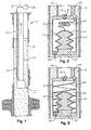
- a subsurface well system 11 having a well bore 13 containing well bore fluid 15 and a pumping system 17 is shown.
- Pumping system 17 is lowered into well bore 13 on a conduit 21.
- Pumping system 17 is supplied with electrical power through an insulated conductor 23 which extends from the surface.
- Conductor 23 is secured and sealed to pumping system 17 at an upper end.
- a power supply 25 and a switch 27 control the electricity and are located at the surface.
- Power supply 25 may be DC or AC, and is preferably single phase.
- Switch 27 is an automatically timed on/off switch which preferably variable.
- pumping system 17 comprises an outer chamber 31, a discharge valve 33, and an intake valve 35 for admitting well bore fluid 15 into chamber 31.
- the interior of chamber 31 communicates with an interior of conduit 21 through discharge valve 33.
- Intake valve 35 is located on a lower end 37 of chamber 31.
- valves 33, 35 comprise check valves.
- Chamber 31 contains an inner, variable volume reservoir 41 which is secured to lower end 37 of chamber 31.
- reservoir 41 is an elastomeric bellows or bladder.
- Reservoir 41 is filled with an environmentally reactive polymer gel 43 that undergoes a significant change in volume in response to an electrical stimulus.
- gel 43 is a mixture of N-isopropylacrylamide, water, an appropriate polymerization initiator and an accelerator. (Gel Sciences, Bedford, Massachusetts.) Reservoir 41 protects gel 43 from contact with well fluid 15.
- a short length of the lower end of conductor 23 is formed into a flexible insulated lead 45.
- Lead 45 extends downward from the upper end of chamber 31 and extends sealingly into an upper end of reservoir 41 in electrical contact with gel 43.
- Chamber 31 is fabricated from an electrically conductive metal.
- Lower end 37 of chamber 31 is also in contact with gel 43 and acts as a ground. Passing electrical current through gel 43 causes it to expand in volume significantly.
- Gel 43 and, thus, reservoir 41 have two states: an unstimulated, contracted state wherein a relatively small volume of chamber 31 is filled, and a stimulated, expanded state wherein a relatively large volume of chamber 31 is filled.
- power supply 25 alternatively passes electricity through gel 43 from conductor 23 to the ground at lower end 37.
- gel 43 and reservoir 41 expand, thereby forcibly expelling the well bore fluid 15 within chamber 31 through discharge valve 33.
- Intake valve 35 is in a closed position and discharge valve 33 is in an open position while gel 43 and reservoir 41 are expanding.
- gel 43 and reservoir 41 contract or collapse, thereby drawing fluid 15 into chamber 31 through intake valve 35.
- Intake valve 35 is in an open position and discharge valve 33 is in a closed position while gel 43 and reservoir 41 are contracting.
- FIG. 3 An alternate embodiment of the invention is shown in Figure 3.
- the gel is formulated to react to the presence of an AC or DC electromagnetic field.
- a pumping system 47 is similar to pumping system 17.
- Pumping system 47 comprises an outer chamber 51, a discharge valve 53, and an intake valve 55 for admitting well bore fluid 15 into chamber 51.
- the interior of chamber 51 communicates with an interior of a conduit 49 through discharge valve 53.
- Intake valve 55 is located on a lower end 57 of chamber 51.
- valves 53, 55 comprise check valves.
- Chamber 51 contains an inner, variable volume bladder or reservoir 61 which is secured to lower end 57 of chamber 51.
- Reservoir 61 is filled with an reactive polymer gel 63 that undergoes a significant change in volume in response to a magnetic field stimulus.
- reservoir 61 is a thin flexible bladder.
- Gel 63 contains metallic particles which increase in temperature when exposed to the magnetic field. The temperature increase significantly increases the volume of gel 63. Gel 63 does not come into contact with well bore fluid 15.
- An insulated electrical conductor 64 extends downward from the surface to chamber 51. A length of the lower end of conductor 64 is formed into a coil 65 with an outer diameter that is approximately equal to an inner diameter of chamber 51.
- Coil 65 extends downward from the upper end of chamber 51 to the lower end 57 of chamber 51 and surrounds reservoir 61. Applying electrical current to coil 65 causes a magnetic field to pass through gel 63, thereby increasing its volume. Gel 63 and, thus, reservoir 61 have two states: an unstimulated, contracted state wherein a relatively small volume of chamber 51 is filled, and a stimulated, expanded state wherein a relatively large volume of chamber 51 is filled.
- a power supply selectively passes electrical current through conductor 64 to produce a magnetic field by coil 65.
- gel 63 and reservoir 61 expand, thereby forcibly expelling the well bore fluid 15 within chamber 51 through discharge valve 53.
- Intake valve 55 is in a closed position and discharge valve 53 is in an open position while gel 63 and reservoir 61 are expanding.
- gel 63 and reservoir 61 contract or collapse, thereby drawing fluid 15 into chamber 51 through intake valve 55.
- Intake valve 55 is in an open position and discharge valve 53 is in a closed position while gel 63 and reservoir 61 are contracting.
- a simple seal section chamber comprising a bag type or labyrinth chamber of commercial types used with electrical centrifugal submersible pumps can be located above it.
- the expansion and contraction of gel 43 would cycle the oil contained within the seal section in and out similar to a motor thermal cycle.
- the well bore fluid 15 discharged into the seal section head as the gel expands would pass through a check valve.
- the seal section chamber drain valve would be left open and contain another check valve. Well bore fluid would be drawn into this check valve as the gel contracts.
- the seal section would have no dynamic seals.
Landscapes
- Engineering & Computer Science (AREA)
- Mechanical Engineering (AREA)
- General Engineering & Computer Science (AREA)
- Mining & Mineral Resources (AREA)
- Life Sciences & Earth Sciences (AREA)
- Geology (AREA)
- Fluid Mechanics (AREA)
- Environmental & Geological Engineering (AREA)
- Physics & Mathematics (AREA)
- General Life Sciences & Earth Sciences (AREA)
- Geochemistry & Mineralogy (AREA)
- Reciprocating Pumps (AREA)
- Electromagnetic Pumps, Or The Like (AREA)
- Details Of Reciprocating Pumps (AREA)
- Soft Magnetic Materials (AREA)
Claims (10)
- Pumpsystem (17)mit einer Pumpe, die eine Kammer (31), ein Einlassventil (35) für die Zuführung eines Fluids in die Kammer (31) und ein Auslassventil (33) zum Abführen von Fluid aus der Kammer (31) hat,mit einem reaktiven polymeren Gel (43), das in der Kammer (31) enthalten ist, dessen Volumen zunimmt, wenn es einem elektrischen Strom ausgesetzt wird, und dessen Volumen abnimmt, wenn der elektrische Strom aufgehoben wird, undmit einer Stromeinspeisung (25), die elektrisch an das Gel (43) angeschlossen ist, um alternativ einen elektrischen Strom durch das Gel (43) hindurchzuführen, wodurch das Gel (43) zum Expandieren und das Fluid in der Kammer (31) zum Entweichen durch das Auslassventil (33) gebracht wird, und um dem Gel (43), wenn der elektrische Strom aufgehoben ist, das Kontraktieren zu ermöglichen, um mehr Fluid durch das Einlassventil (35) in die Kammer (31) zu ziehen.
- Pumpsystem nach Anspruch 1, welches weiterhin einen elektrischen Leiter (23, 45), der von der Stromeinspeisung (25) wegführt und mit dem Gel (43) in einem Speicher (41) mit variablem Volumen verbunden ist, und eine elektrische Masse (37) aufweist, die mit dem Gel (43) in dem Speicher (41) verbunden ist.
- Pumpsystem (47)mit einer Pumpe, die eine Kammer (51), ein Einlassventil (55) für die Zuführung eines Fluids in die Kammer (51) und ein Auslassventil (53) zum Abführen des Fluids (43) aus der Kammer (51) hat,mit einem reaktiven polymeren Gel (63), das in der Kammer (51) enthalten ist, wobei das Gel (63), wenn es einem elektromagnetischen Feld ausgesetzt ist, ein erstes Volumen und, wenn das elektromagnetische Feld aufgehoben wird, ein zweites Volumen hat, wobei sich das erste Volumen beträchtlich von dem zweiten Volumen unterscheidet, undmit einer elektromagnetischen Wicklung (65), die das Gel (63) umgibt und mit einer Stromquelle (25) verbunden ist, die das Gel (63) einem elektromagnetischen Feld selektiv und alternativ aussetzt, um das Gel (63) zum Expandieren und zum Austreiben eines Teils des Fluids in der Kammer (51) durch das Auslassventil (53) zu bringen.
- Pumpsystem nach Anspruch 3, bei welchem das erste Volumen größer ist als das zweite Volumen ist.
- Pumpsystem nach Anspruch 3 oder 4, bei welchem das elektromagnetische Feld ein Wechselstrom- oder Gleichstromfeld ist.
- Pumpsystem nach einem der Ansprüche 3 bis 5, bei welchem das Gel (63) metallische Teilchen enthält.
- Pumpsystem nach einem der Ansprüche 3 bis 6, bei welchem die Wicklung (65) sich in der Kammer (51) befindet und einen Speicher (61) mit variablem Volumen umgibt, der das Gel (63) einschließt.
- Pumpsystem nach einem der vorhergehenden Ansprüche, bei welchem das Gel (43, 63) eine Mischung aus N-lsopropylacrylamid, Wasser, einem geeigneten Polymerisationsinitiator und einem Beschleuniger ist.
- Pumpsystem nach einem der vorhergehenden Ansprüche, welches weiterhin einen Speicher (41, 61), eine flexible Blase oder einen elastomeren Balg aufweist, der/die das Gel (43, 63) einschließt.
- Pumpsystem nach einem der vorhergehenden Ansprüche zum Pumpen eines Bohrlochfluids in ein Bohrloch, wobei die Pumpe in das Bohrloch abgesenkt ist und durch entsprechendes Aufschwellen und Schrumpfen des Gels (43, 63) als Tauchpumpe arbeitet.
Applications Claiming Priority (3)
| Application Number | Priority Date | Filing Date | Title |
|---|---|---|---|
| US918978 | 1992-07-24 | ||
| US08/918,978 US6015266A (en) | 1997-08-27 | 1997-08-27 | Reactive material reciprocating submersible pump |
| PCT/US1998/016867 WO1999010653A1 (en) | 1997-08-27 | 1998-08-12 | Reactive polymer gel actuated pumping system |
Publications (2)
| Publication Number | Publication Date |
|---|---|
| EP1007846A1 EP1007846A1 (de) | 2000-06-14 |
| EP1007846B1 true EP1007846B1 (de) | 2002-11-20 |
Family
ID=25441269
Family Applications (1)
| Application Number | Title | Priority Date | Filing Date |
|---|---|---|---|
| EP98939946A Expired - Lifetime EP1007846B1 (de) | 1997-08-27 | 1998-08-12 | Reaktives polymergelbetägtigtes pumpsystem |
Country Status (7)
| Country | Link |
|---|---|
| US (1) | US6015266A (de) |
| EP (1) | EP1007846B1 (de) |
| AU (1) | AU8829398A (de) |
| CA (1) | CA2302052C (de) |
| DE (1) | DE69809565T2 (de) |
| GB (1) | GB2342960B (de) |
| WO (1) | WO1999010653A1 (de) |
Families Citing this family (11)
| Publication number | Priority date | Publication date | Assignee | Title |
|---|---|---|---|---|
| US6679324B2 (en) | 1999-04-29 | 2004-01-20 | Shell Oil Company | Downhole device for controlling fluid flow in a well |
| SE9902474D0 (sv) * | 1999-06-30 | 1999-06-30 | Amersham Pharm Biotech Ab | Polymer valves |
| US6321845B1 (en) * | 2000-02-02 | 2001-11-27 | Schlumberger Technology Corporation | Apparatus for device using actuator having expandable contractable element |
| US6433991B1 (en) | 2000-02-02 | 2002-08-13 | Schlumberger Technology Corp. | Controlling activation of devices |
| US6681849B2 (en) * | 2001-08-22 | 2004-01-27 | Baker Hughes Incorporated | Downhole packer system utilizing electroactive polymers |
| US7198474B2 (en) * | 2003-04-07 | 2007-04-03 | Hewlett-Packard Development Company, L.P. | Pump having shape memory actuator and fuel cell system including the same |
| US7559358B2 (en) * | 2005-08-03 | 2009-07-14 | Baker Hughes Incorporated | Downhole uses of electroactive polymers |
| CN101784792B (zh) * | 2007-07-20 | 2013-06-12 | 普拉德研究及开发股份有限公司 | 具有冗余轴密封的泵用电动机保护器 |
| US9145885B2 (en) * | 2011-04-18 | 2015-09-29 | Saudi Arabian Oil Company | Electrical submersible pump with reciprocating linear motor |
| EP3052805B1 (de) | 2013-10-02 | 2019-05-01 | Saudi Arabian Oil Company | Peristaltische tauchpumpe |
| GB2608743B (en) | 2020-03-31 | 2024-07-10 | Schlumberger Technology Bv | Electric submersible pump systems |
Family Cites Families (12)
| Publication number | Priority date | Publication date | Assignee | Title |
|---|---|---|---|---|
| GB1151058A (en) * | 1968-01-26 | 1969-05-07 | Mullard Ltd | A device for Pumping Electrically Heated Liquid. |
| US3702067A (en) * | 1969-11-04 | 1972-11-07 | Stewart Research | Force transmission and apparatus |
| US4018547A (en) * | 1975-08-28 | 1977-04-19 | Rogen Neil E | Pumping by wire elongation |
| SU962671A1 (ru) * | 1981-02-18 | 1982-09-30 | За витель п В.С.Крючков | Гидропривод объемного насоса |
| US4472113A (en) * | 1982-01-22 | 1984-09-18 | Rogen Neil E | Pumping by martensitic transformation utilization |
| DE68913894T2 (de) * | 1988-10-21 | 1994-09-22 | Canon Kk | Verfahren zur Herstellung eines Polymergels, Polymergel und Stellglied, das dieses benutzt. |
| US5288214A (en) * | 1991-09-30 | 1994-02-22 | Toshio Fukuda | Micropump |
| JPH05104737A (ja) * | 1991-10-17 | 1993-04-27 | Minolta Camera Co Ltd | インクジエツト記録装置 |
| US5284330A (en) * | 1992-06-18 | 1994-02-08 | Lord Corporation | Magnetorheological fluid devices |
| US5334629A (en) * | 1992-08-27 | 1994-08-02 | The United States Of America As Represented By The Secretary Of The Navy | Control of continuous phase pH using visible light to activate pH-dependent fibers and gels in a controlled and reversible manner |
| US5534186A (en) * | 1993-12-15 | 1996-07-09 | Gel Sciences, Inc. | Gel-based vapor extractor and methods |
| WO1996002276A2 (en) * | 1994-07-18 | 1996-02-01 | Gel Sciences, Inc. | Novel polymer gel networks and methods of use |
-
1997
- 1997-08-27 US US08/918,978 patent/US6015266A/en not_active Expired - Fee Related
-
1998
- 1998-08-12 AU AU88293/98A patent/AU8829398A/en not_active Abandoned
- 1998-08-12 DE DE69809565T patent/DE69809565T2/de not_active Expired - Fee Related
- 1998-08-12 GB GB0004697A patent/GB2342960B/en not_active Expired - Fee Related
- 1998-08-12 CA CA002302052A patent/CA2302052C/en not_active Expired - Fee Related
- 1998-08-12 EP EP98939946A patent/EP1007846B1/de not_active Expired - Lifetime
- 1998-08-12 WO PCT/US1998/016867 patent/WO1999010653A1/en not_active Ceased
Also Published As
| Publication number | Publication date |
|---|---|
| GB2342960A (en) | 2000-04-26 |
| GB0004697D0 (en) | 2000-04-19 |
| DE69809565T2 (de) | 2003-07-17 |
| GB2342960B (en) | 2002-04-10 |
| CA2302052A1 (en) | 1999-03-04 |
| AU8829398A (en) | 1999-03-16 |
| CA2302052C (en) | 2002-01-08 |
| EP1007846A1 (de) | 2000-06-14 |
| US6015266A (en) | 2000-01-18 |
| DE69809565D1 (de) | 2003-01-02 |
| WO1999010653A1 (en) | 1999-03-04 |
Similar Documents
| Publication | Publication Date | Title |
|---|---|---|
| US11268520B2 (en) | Centrifugal pump with adaptive pump stages | |
| US5554897A (en) | Downhold motor cooling and protection system | |
| US7387500B2 (en) | Hydro elastic pump which pumps using non-rotary bladeless and valveless operations | |
| US6015266A (en) | Reactive material reciprocating submersible pump | |
| JP6890588B2 (ja) | 可変圧力容器 | |
| GB2364750A (en) | Reactive polymer gel actuated pumping system | |
| CN109944777A (zh) | 记忆合金弹簧驱动的微小型隔膜泵及采用其的装置、方法 | |
| CN210135058U (zh) | 记忆合金弹簧驱动的微小型隔膜泵及采用其的装置 | |
| SU1724933A1 (ru) | Перистальтический насос | |
| KR100337772B1 (ko) | 수중 모터 펌프의 오일 챔버내 압력 감쇄장치 | |
| KR20010046717A (ko) | 디퓨져/노즐 펌프 | |
| JPH03100376A (ja) | ポンプ | |
| SU909290A1 (ru) | Электромагнитный скважинный насос | |
| RU2065530C1 (ru) | Погружной диафрагменный электронасос для подъема жидкости из скважины | |
| SU688689A1 (ru) | Объемный насос | |
| RU2802907C1 (ru) | Гидроштанговый привод погружного объемного насоса (варианты) | |
| SU1245752A1 (ru) | Плунжерный насос | |
| SU785559A1 (ru) | Электрогидравлический насос | |
| SU1370301A1 (ru) | Привод возвратно-поступательного действи поршневого скважинного насоса | |
| SU1714191A1 (ru) | Насос с тепловым приводом | |
| SU1239399A1 (ru) | Объемный насос | |
| US20040168437A1 (en) | Vapor over liquid diaphragm engine | |
| SU709831A1 (ru) | Электромагнитный объемный насос | |
| SU954606A1 (ru) | Объемный насос | |
| RU2171399C1 (ru) | Насосный агрегат |
Legal Events
| Date | Code | Title | Description |
|---|---|---|---|
| PUAI | Public reference made under article 153(3) epc to a published international application that has entered the european phase |
Free format text: ORIGINAL CODE: 0009012 |
|
| 17P | Request for examination filed |
Effective date: 20000320 |
|
| AK | Designated contracting states |
Kind code of ref document: A1 Designated state(s): AT BE CH CY DE DK ES FI FR GB GR IE IT LI LU MC NL PT SE Kind code of ref document: A1 Designated state(s): DE FR |
|
| 17Q | First examination report despatched |
Effective date: 20010508 |
|
| GRAG | Despatch of communication of intention to grant |
Free format text: ORIGINAL CODE: EPIDOS AGRA |
|
| GRAG | Despatch of communication of intention to grant |
Free format text: ORIGINAL CODE: EPIDOS AGRA |
|
| GRAH | Despatch of communication of intention to grant a patent |
Free format text: ORIGINAL CODE: EPIDOS IGRA |
|
| RBV | Designated contracting states (corrected) |
Designated state(s): DE FR |
|
| GRAH | Despatch of communication of intention to grant a patent |
Free format text: ORIGINAL CODE: EPIDOS IGRA |
|
| GRAA | (expected) grant |
Free format text: ORIGINAL CODE: 0009210 |
|
| AK | Designated contracting states |
Kind code of ref document: B1 Designated state(s): DE FR |
|
| REF | Corresponds to: |
Ref document number: 69809565 Country of ref document: DE Date of ref document: 20030102 |
|
| ET | Fr: translation filed | ||
| PLBE | No opposition filed within time limit |
Free format text: ORIGINAL CODE: 0009261 |
|
| STAA | Information on the status of an ep patent application or granted ep patent |
Free format text: STATUS: NO OPPOSITION FILED WITHIN TIME LIMIT |
|
| 26N | No opposition filed |
Effective date: 20030821 |
|
| PGFP | Annual fee paid to national office [announced via postgrant information from national office to epo] |
Ref country code: DE Payment date: 20071001 Year of fee payment: 10 |
|
| PGFP | Annual fee paid to national office [announced via postgrant information from national office to epo] |
Ref country code: FR Payment date: 20070817 Year of fee payment: 10 |
|
| REG | Reference to a national code |
Ref country code: FR Ref legal event code: ST Effective date: 20090430 |
|
| PG25 | Lapsed in a contracting state [announced via postgrant information from national office to epo] |
Ref country code: FR Free format text: LAPSE BECAUSE OF NON-PAYMENT OF DUE FEES Effective date: 20080901 Ref country code: DE Free format text: LAPSE BECAUSE OF NON-PAYMENT OF DUE FEES Effective date: 20090303 |