EP1007905B1 - Verfahren zum messen der orientierung einer oberfläche - Google Patents
Verfahren zum messen der orientierung einer oberfläche Download PDFInfo
- Publication number
- EP1007905B1 EP1007905B1 EP97951412A EP97951412A EP1007905B1 EP 1007905 B1 EP1007905 B1 EP 1007905B1 EP 97951412 A EP97951412 A EP 97951412A EP 97951412 A EP97951412 A EP 97951412A EP 1007905 B1 EP1007905 B1 EP 1007905B1
- Authority
- EP
- European Patent Office
- Prior art keywords
- line
- light
- detector
- relative
- lines
- Prior art date
- Legal status (The legal status is an assumption and is not a legal conclusion. Google has not performed a legal analysis and makes no representation as to the accuracy of the status listed.)
- Expired - Lifetime
Links
- 238000000034 method Methods 0.000 title claims abstract description 19
- 230000005855 radiation Effects 0.000 claims abstract description 19
- 239000000758 substrate Substances 0.000 claims description 5
- 238000001514 detection method Methods 0.000 claims 1
- 238000005259 measurement Methods 0.000 description 10
- 238000005096 rolling process Methods 0.000 description 2
- 239000000446 fuel Substances 0.000 description 1
- 239000011159 matrix material Substances 0.000 description 1
- 230000003287 optical effect Effects 0.000 description 1
- 238000010408 sweeping Methods 0.000 description 1
Images

Classifications
-
- G—PHYSICS
- G01—MEASURING; TESTING
- G01B—MEASURING LENGTH, THICKNESS OR SIMILAR LINEAR DIMENSIONS; MEASURING ANGLES; MEASURING AREAS; MEASURING IRREGULARITIES OF SURFACES OR CONTOURS
- G01B11/00—Measuring arrangements characterised by the use of optical techniques
- G01B11/26—Measuring arrangements characterised by the use of optical techniques for measuring angles or tapers; for testing the alignment of axes
- G01B11/275—Measuring arrangements characterised by the use of optical techniques for measuring angles or tapers; for testing the alignment of axes for testing wheel alignment
-
- G—PHYSICS
- G01—MEASURING; TESTING
- G01B—MEASURING LENGTH, THICKNESS OR SIMILAR LINEAR DIMENSIONS; MEASURING ANGLES; MEASURING AREAS; MEASURING IRREGULARITIES OF SURFACES OR CONTOURS
- G01B11/00—Measuring arrangements characterised by the use of optical techniques
- G01B11/26—Measuring arrangements characterised by the use of optical techniques for measuring angles or tapers; for testing the alignment of axes
-
- G—PHYSICS
- G01—MEASURING; TESTING
- G01B—MEASURING LENGTH, THICKNESS OR SIMILAR LINEAR DIMENSIONS; MEASURING ANGLES; MEASURING AREAS; MEASURING IRREGULARITIES OF SURFACES OR CONTOURS
- G01B2210/00—Aspects not specifically covered by any group under G01B, e.g. of wheel alignment, caliper-like sensors
- G01B2210/10—Wheel alignment
- G01B2210/20—Vehicle in a state of translatory motion
-
- G—PHYSICS
- G01—MEASURING; TESTING
- G01B—MEASURING LENGTH, THICKNESS OR SIMILAR LINEAR DIMENSIONS; MEASURING ANGLES; MEASURING AREAS; MEASURING IRREGULARITIES OF SURFACES OR CONTOURS
- G01B2210/00—Aspects not specifically covered by any group under G01B, e.g. of wheel alignment, caliper-like sensors
- G01B2210/10—Wheel alignment
- G01B2210/24—Specially developed for using with trucks or other heavy-duty vehicles
-
- G—PHYSICS
- G01—MEASURING; TESTING
- G01B—MEASURING LENGTH, THICKNESS OR SIMILAR LINEAR DIMENSIONS; MEASURING ANGLES; MEASURING AREAS; MEASURING IRREGULARITIES OF SURFACES OR CONTOURS
- G01B2210/00—Aspects not specifically covered by any group under G01B, e.g. of wheel alignment, caliper-like sensors
- G01B2210/10—Wheel alignment
- G01B2210/30—Reference markings, reflector, scale or other passive device
- G01B2210/306—Mirror, prism or other reflector
Definitions
- the present invention relates to a method of measuring the orientation of a surface relative to a geometric reference, such as an axis or a plane, comprising the following steps: projecting by means of a radiation source a first line of light onto the surface; and detecting by means of a first detector the position of the first line of light projected on the surface relative to the position of a first reference line on the surface, detecting the angle between the first line of light projected onto the surface and the first reference line ; projecting, by means of the radiation source (5), a second line of light (8) onto the surface; detecting, by means of the first detector, the position of the second line of light projected onto the surface relative to the position of a second reference line on the surface; and detecting the angle between the second line of light projected onto the surface and the second reference line.
- US-A-5 463 463 describes an apparatus for determining the position of an object, such as a car wheel on an actuator assembly, with respect to a reference system.
- a target is attached to the wheel, which is rotated.
- a projector directs two lines of light onto the target surface.
- a detector determines the position of the two lines projected onto the target relative to the position of respective reference lines and computes the angular orientation of the wheel.
- the measurement is carried out on a vehicle rolling on a substrate.
- the projector and the detector are provided in a measuring head which is mounted in a fixed relationship to the vehicle.
- the purpose of the present invention is to provide touch less measurement of the orientation of a rotating surface relative to a geometric reference which allows an accurate measurement to be rapidly obtained.
- the measurement provides values for the angle of the surface and its distance relative to a geometric reference. Based on these values, the angle and distance of the surface relative to the geometric reference can be adjusted, if so desired.
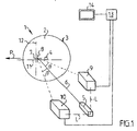
- Fig. 1 shows a measuring device I according to the present invention for touchless measurement of the orientation of a surface 2 relative to a geometric reference, such as an axis or a plane.
- a geometric reference such as an axis or a plane.
- the angles are measured at which a rotating disc 3 is oriented relative to an imaginary reference axis in space.
- the disc 3 can, at the same time as it rotates, also roll in the direction of the arrow P. If the angle or angles of the disc 3 are measured, the direction of the rotational axis 4 of the disc 3 can be determined. And if so desired, the disc 3 can be set so that its rotational axis 4 coincides with the reference axis.
- the measuring device 1 comprises a radiation source 5 in the form of at least one laser, which is arranged, by means of a light beam 6 in the form of laser rays, to project first and second lines of light 7 and 8, respectively, in the form of laser lines on the surface 2.
- First and second detectors 9 and 10, respectively, are arranged to detect the first and second laser line 7, 8 on the surface 2.
- the first detector 9 is arranged so that the angle ⁇ between the light beam 6 emitted by the radiation source 5 and the aiming direction of the first detector 9 towards the surface 2 is non-zero.
- the angle ⁇ is preferably in the interval 20°- 60°, but even angles outside this interval are conceivable.
- the other detector 10 as well is arranged so that the angle ⁇ between the light beam 6 emitted by the radiation source 5 and the aiming direction of the second detector 10 towards the surface 2 is non-zero.
- the angle ⁇ is preferably selected to be the same angle as ⁇ but can be different. If the first and second laser lines 7, 8 intersect or orthogonally to form a cross, the first and second detectors 9, 10 should be arranged at right angles with the radiation source 5 at the corner of the angle, as indicated by the dashed line L in Fig. 1.
- the radiation source 5 comprises at least one laser which, by means of an optical device (not shown), produces the first and second laser lines 7, 8.
- the radiation source 5 can also comprise a plurality of lasers, one for each laser line 7, 8.
- the first and second detectors 9, 10 can each be a common video camera of CCD-type, but in order to increase the accuracy of the measurement, preferably a smart image sensor of the type MAPP (Matrix Array Picture Processor) is used.
- MAPP Microx Array Picture Processor
- the method of measuring the orientation of the surface 2 relative to the geometric reference comprises the steps of projecting from the radiation source 5 in the form of a laser first and second lines of light 7, 8 in the form of two laser lines formed on the surface 2.
- the first and second detectors 9, 10 thereafter detect, sequentially or simultaneously, the positions and angles of the laser lines 7, 8 projected on the surface relative to the positions of first and second reference lines 11 and 12, respectively, on the surface.
- the first and second laser lines 7, 8 intersect orthogonally, but this is no precondition for carrying out the measurement.
- the laser lines 7, 8 can intersect at an angle different from 90°.
- the laser lines 7, 8 can also be projected at different locations on the surface 2, so that they do not need to intersect.
- the detected positions and angles for the first and second laser lines 7, 8 are sent to a processor 13 which processes the detected information and, after processing, presents the orientation of the surface 2 relative to the geometric reference.
- This information can be presented on a monitor 14, for example.
- the method and device according to the invention can, in accordance with a first embodiment, be used to reduce vehicle tyre wear arising as a result of wheel misalignment and/or trailer misplacement and to achieve the smallest projected width of the vehicle in the driving direction to thereby minimize air drag and fuel consumption.
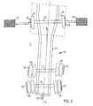
- Fig. 2 shows schematically a view from above of a vehicle 15 travelling forward in the direction F with the wheels 16 rolling on a substrate U between at least two measuring units 17, 18 standing free from the vehicle 15.
- Each measuring unit 17, 18 comprises a radiation source 5' in the form of a laser which, as the vehicle 15 passes the measuring unit 17, 18, projects first and second laser lines onto the outside of each wheel 16, i.e. the side of the wheel facing away from the vehicle 15.
- a reflecting means 19 has been mounted on the outside of each wheel 16. The laser lines from each radiation source 5' are projected on this reflecting means 19.
- the information detected by the detector 9' is processed in a processor 13' which provides values for the alignment of the rotational axis of each wheel 16, the distance of each wheel 16 to its respective measuring unit 17, 18, the distance between the respective wheels 16 on either side of the vehicle 15 and the longitudinal geometrical centerline C of the vehicle 15.
- the measured values for the alignment of the rotational axis of each wheel 16 are compared with predetermined ideal values for the alignment of the rotational axes of the wheels 16.
- the wheels 16 are adjusted so that the differences between the measured values for the alignment of the rotational axis of each wheel 16 and the ideal values for the alignment of the rotational axis of each wheel 16 are as small as possible.
- two detectors are disposed at each measuring unit, with the first detector detecting the first laser line and the second detector detecting the second laser line.
- the time it takes for the wheels 16 to pass each measuring unit 17, 18 is measured.
- the speed of the vehicle 15 is known, the distance between each wheel 16 on each side of the vehicle 15 can be computed.
- a speedometer (not shown) in the form of a laser for example, can be arranged in front of or above the vehicle 15. The laser sends a measuring ray towards the vehicle 15 when it passes the measuring unit 17, 18, and the speed of the vehicle 15 can be measured.
- the speedometer can be coupled to the processor 13' which computes the distance between the respective wheel 16 on each side of the vehicle 15 based on the known speed and the time it takes for the wheels 16 to pass the measuring units 17, 18.
- Fig. 3 shows a schematic view of a vehicle 15 as seen from behind, passing three measuring units 17, 18, 22.
- a measuring unit 22 is arranged above the vehicle 15 and comprises a radiation source 5' in the form of a laser, which projects first and second laser lines on the towing hitch 23 of the vehicle 15.
- a reflecting means 24 is mounted on the towing hitch 23 of the vehicle 15, and laser lines from the radiation source 5' are projected on the reflecting means 24.
- the information detected by the detector 9' is processed in the processor 13' showing how far the towing hitch 23 is remote from the longitudinal geometrical centerline C of the vehicle 15 and how high above the road surface U the towing hitch is situated.
- the result of the measurement can be presented on the monitor 14', for example.
- the towing hitch 23 is moved or the frame 25 of the vehicle 15 is adjusted so that the towing hitch 23 is placed on the longitudinal geometric centerline C of the vehicle 15.
- the reflecting means 19, 24 can be a flat disc mounted on the outside of each wheel 16 and on the towing hitch 23.
- the laser lines can be projected directly on the tyre side or rim (not shown) of each wheel 16 and directly on the towing hitch 23.
Landscapes
- Physics & Mathematics (AREA)
- General Physics & Mathematics (AREA)
- Length Measuring Devices By Optical Means (AREA)
Claims (7)
- Verfahren zum Messen der Ausrichtung einer Oberfläche (2) in Bezug auf eine geometrische Referenz, wie eine Achse oder eine Ebene, umfassend die folgenden Schritte:dadurch gekennzeichnet, dassProjizieren einer ersten Lichtlinie (7) mit einer Strahlungsquelle (5) auf die Oberfläche; undErfassen der Position der auf der Oberfläche (2) projizierten, ersten Lichtlinie (7) mittels eines ersten Detektors (9) in Bezug auf die Position einer ersten Referenzlinie (11) auf der Oberfläche (2),Erfassen des Winkels zwischen der auf die Oberfläche (2) projizierten, ersten Lichtlinie (7) und der ersten Referenzlinie (11);Projizieren einer zweiten Lichtlinie (8) mittels einer Strahlungsquelle (5) auf die Oberfläche (2);Erfassen der Position der auf die Oberfläche (2) projizierten, zweiten Lichtlinie (8) mittels des ersten Detektors (9) in Bezug auf die Position einer zweiten Referenzlinie (12) auf der Oberfläche (2); undErfassen des Winkels der zwischen der auf die Oberfläche (2) projizierten, zweiten Lichtlinie (8) und der zweiten Referenzlinie (12),die Erfassung der Position der ersten und der zweiten Lichtlinie (7, 8) vorgenommen wird, wenn die Oberfläche (2) rotiert und auf einem Substrat (U) in einer Richtung (P) rollt, die die Strahlungsquelle (5) und den ersten Detektor (9) passiert.
- Verfahren nach Anspruch 1, dadurch gekennzeichnet, dass die erste und die zweite Lichtlinie (7, 8) einander schneiden.
- Verfahren nach Anspruch 1 oder 2, dadurch gekennzeichnet, dass die erste und die zweite Lichtlinie (7, 8) einander orthogonal schneiden.
- Verfahren nach einem oder mehreren der vorhergehenden Ansprüche, dadurch gekennzeichnet, dass die zweite Lichtlinie (7, 8) durch einen zweiten Detektor (10) erfasst wird, wenn die Oberfläche (2) rotiert und auf einem Substrat (U) in einer Richtung (P) rollt, welche den zweiten Detektor (10) passiert.
- Verfahren nach einem oder mehreren der vorhergehenden Ansprüche, dadurch gekennzeichnet, dass die erfassten Positionen und Winkel der ersten und der zweiten Lichtlinie (7, 8) weiter zu einem Prozessor (13) geschickt werden, der die erfasste Information verarbeitet und der nach der Verarbeitung die Ausrichtung der Oberfläche (2) in Bezug auf die geometrische Referenz bereitstellt.
- Verfahren nach Anspruch 5, dadurch gekennzeichnet, dass eine Reflektiereinrichtung mittels einer ebenen Scheibe (19) an der Oberfläche (2) montiert ist.
- Verfahren nach Anspruch 6, dadurch gekennzeichnet, dass ein Ausgleich eines Winkelfehlers zwischen einer Normalen zu der Scheibe (19) und einer Rotationsachse der rotierenden Oberfläche (12) in dem Prozessor (13) vorgenommen wird.
Applications Claiming Priority (3)
| Application Number | Priority Date | Filing Date | Title |
|---|---|---|---|
| SE9604742 | 1996-12-20 | ||
| SE9604742A SE510343C2 (sv) | 1996-12-20 | 1996-12-20 | Förfarande för att mäta orienteringen av en yta i förhållande till en geometrisk referens |
| PCT/SE1997/002192 WO1998028594A1 (en) | 1996-12-20 | 1997-12-19 | Device and method for measuring the orientation of a surface |
Publications (2)
| Publication Number | Publication Date |
|---|---|
| EP1007905A1 EP1007905A1 (de) | 2000-06-14 |
| EP1007905B1 true EP1007905B1 (de) | 2005-06-29 |
Family
ID=20405099
Family Applications (1)
| Application Number | Title | Priority Date | Filing Date |
|---|---|---|---|
| EP97951412A Expired - Lifetime EP1007905B1 (de) | 1996-12-20 | 1997-12-19 | Verfahren zum messen der orientierung einer oberfläche |
Country Status (5)
| Country | Link |
|---|---|
| EP (1) | EP1007905B1 (de) |
| AU (1) | AU5506198A (de) |
| DE (1) | DE69733672T2 (de) |
| SE (1) | SE510343C2 (de) |
| WO (1) | WO1998028594A1 (de) |
Families Citing this family (1)
| Publication number | Priority date | Publication date | Assignee | Title |
|---|---|---|---|---|
| ITMI991103A1 (it) | 1999-05-19 | 2000-11-19 | Gieffe Immobiliare S N C Di Gi | Procedimento ed apparecchiatura per la musica degli angoli di assettodi un autoveicolo in particolare di convergenza e campanatura delle ru |
Family Cites Families (6)
| Publication number | Priority date | Publication date | Assignee | Title |
|---|---|---|---|---|
| US4745469A (en) * | 1987-02-18 | 1988-05-17 | Perceptron, Inc. | Vehicle wheel alignment apparatus and method |
| DK183089D0 (da) * | 1989-04-14 | 1989-04-14 | Oedegaard & Danneskiold Samsoe | Anlaeg til sporbaseret maaling af hjulprofilen paa j ernbanehjul |
| GB2280259A (en) * | 1993-07-24 | 1995-01-25 | British Aerospace | Detecting angular displacement. |
| US5463463A (en) * | 1994-01-25 | 1995-10-31 | Mts System Corporation | Optical motion sensor |
| DE4419584A1 (de) * | 1994-06-03 | 1995-12-07 | Daimler Benz Aerospace Ag | Verfahren zur berührungslosen, dynamischen meßtechnischen Erfassung von Winkellagen eines rotierenden Rotationskörpers |
| US5600435A (en) * | 1995-05-24 | 1997-02-04 | Fori Automation, Inc. | Intelligent sensor method and apparatus for an optical wheel alignment machine |
-
1996
- 1996-12-20 SE SE9604742A patent/SE510343C2/sv not_active IP Right Cessation
-
1997
- 1997-12-19 DE DE69733672T patent/DE69733672T2/de not_active Expired - Fee Related
- 1997-12-19 EP EP97951412A patent/EP1007905B1/de not_active Expired - Lifetime
- 1997-12-19 AU AU55061/98A patent/AU5506198A/en not_active Abandoned
- 1997-12-19 WO PCT/SE1997/002192 patent/WO1998028594A1/en not_active Ceased
Also Published As
| Publication number | Publication date |
|---|---|
| DE69733672D1 (de) | 2005-08-04 |
| SE510343C2 (sv) | 1999-05-17 |
| WO1998028594A1 (en) | 1998-07-02 |
| AU5506198A (en) | 1998-07-17 |
| SE9604742L (sv) | 1998-06-21 |
| SE9604742D0 (sv) | 1996-12-20 |
| EP1007905A1 (de) | 2000-06-14 |
| DE69733672T2 (de) | 2006-05-04 |
Similar Documents
| Publication | Publication Date | Title |
|---|---|---|
| JP4248264B2 (ja) | 車両の特徴的姿勢パラメータの測定装置及びシステム | |
| JP4406506B2 (ja) | 自動車のホイールアラインメントおよびアクスルアラインメントを求めるための装置 | |
| US5532816A (en) | Laser tracking wheel alignment measurement apparatus and method | |
| US4402603A (en) | Four wheel alignment apparatus and method | |
| US6915228B2 (en) | Method and device for calibrating an image sensor system in a motor vehicle | |
| US10848316B1 (en) | Non-contact vehicle measurement system | |
| US6397164B1 (en) | Device for determining the wheel and/or axle geometry of motor vehicles | |
| KR101423348B1 (ko) | 바퀴 조립체 배향 결정 장치 및 차량 바퀴 정렬 위치 결정 방법 | |
| US5519489A (en) | Vehicle alignment system | |
| EP0749563B1 (de) | Bestimmung der kraftfahrradpositionen und orientierungen | |
| US6657711B1 (en) | Vehicle wheel alignment measuring apparatus | |
| JP3197529B2 (ja) | 車輪アライメント特性の非接触式測定方法とその測定装置 | |
| EP1216396B1 (de) | Verfahren und vorrichtung zur messung des abrollradius eines fahrzeugrades | |
| US5818574A (en) | Method and apparatus for vehicle wheel alignment testing | |
| EP0946857B1 (de) | Verfahren und vorrichtung zur ausrichtung von fahrzeugrädern | |
| KR19980033400A (ko) | 차량바퀴의 캠버와 캐스터의 비접촉측정방법과 장치 | |
| JP2003508743A (ja) | 車両のヘッドライト又は距離センサのための調節機器を備えた調節装置 | |
| JPH04295710A (ja) | 角度の光学的測定方法および装置 | |
| EP0943890A2 (de) | Verfahren und Apparat zum Messen der karakteristischen Positionswinkel eines Fahrzeugs | |
| EP0611948B1 (de) | System zum Messen des Radstands eines Kraftfahrzeugrahmens und des Quer- und Längsversatzes seiner lenkbaren Räder | |
| EP1007905A1 (de) | Vorrichtung und verfahren zum messen der orientation eines oberfläches | |
| CN114111606A (zh) | 测量车辆参数的系统和测量车辆参数的方法 | |
| JP2021148465A (ja) | 検知装置、センサ調整システム、車両、及びセンサの調整方法 | |
| JP2001249004A (ja) | 車輪計測装置 | |
| EP0819910A1 (de) | Verfahren und System zur Spurmessung an Rädern von Kraftfahrzeugen |
Legal Events
| Date | Code | Title | Description |
|---|---|---|---|
| PUAI | Public reference made under article 153(3) epc to a published international application that has entered the european phase |
Free format text: ORIGINAL CODE: 0009012 |
|
| 17P | Request for examination filed |
Effective date: 19990628 |
|
| AK | Designated contracting states |
Kind code of ref document: A1 Designated state(s): DE FR GB IT NL SE |
|
| 17Q | First examination report despatched |
Effective date: 20040507 |
|
| GRAP | Despatch of communication of intention to grant a patent |
Free format text: ORIGINAL CODE: EPIDOSNIGR1 |
|
| GRAP | Despatch of communication of intention to grant a patent |
Free format text: ORIGINAL CODE: EPIDOSNIGR1 |
|
| RTI1 | Title (correction) |
Free format text: METHOD FOR MEASURING THE ORIENTATION OF A SURFACE |
|
| GRAS | Grant fee paid |
Free format text: ORIGINAL CODE: EPIDOSNIGR3 |
|
| GRAA | (expected) grant |
Free format text: ORIGINAL CODE: 0009210 |
|
| AK | Designated contracting states |
Kind code of ref document: B1 Designated state(s): DE FR GB IT NL SE |
|
| REG | Reference to a national code |
Ref country code: GB Ref legal event code: FG4D |
|
| RIN1 | Information on inventor provided before grant (corrected) |
Inventor name: ASTRAND, ERIK Inventor name: ASTROEM, ANDERS |
|
| REF | Corresponds to: |
Ref document number: 69733672 Country of ref document: DE Date of ref document: 20050804 Kind code of ref document: P |
|
| REG | Reference to a national code |
Ref country code: SE Ref legal event code: TRGR |
|
| ET | Fr: translation filed | ||
| PLBE | No opposition filed within time limit |
Free format text: ORIGINAL CODE: 0009261 |
|
| STAA | Information on the status of an ep patent application or granted ep patent |
Free format text: STATUS: NO OPPOSITION FILED WITHIN TIME LIMIT |
|
| 26N | No opposition filed |
Effective date: 20060330 |
|
| PGFP | Annual fee paid to national office [announced via postgrant information from national office to epo] |
Ref country code: NL Payment date: 20071203 Year of fee payment: 11 |
|
| PGFP | Annual fee paid to national office [announced via postgrant information from national office to epo] |
Ref country code: IT Payment date: 20071220 Year of fee payment: 11 |
|
| PGFP | Annual fee paid to national office [announced via postgrant information from national office to epo] |
Ref country code: SE Payment date: 20071205 Year of fee payment: 11 |
|
| PGFP | Annual fee paid to national office [announced via postgrant information from national office to epo] |
Ref country code: GB Payment date: 20071219 Year of fee payment: 11 Ref country code: FR Payment date: 20071210 Year of fee payment: 11 |
|
| PGFP | Annual fee paid to national office [announced via postgrant information from national office to epo] |
Ref country code: DE Payment date: 20071213 Year of fee payment: 11 |
|
| EUG | Se: european patent has lapsed | ||
| GBPC | Gb: european patent ceased through non-payment of renewal fee |
Effective date: 20081219 |
|
| NLV4 | Nl: lapsed or anulled due to non-payment of the annual fee |
Effective date: 20090701 |
|
| REG | Reference to a national code |
Ref country code: FR Ref legal event code: ST Effective date: 20090831 |
|
| PG25 | Lapsed in a contracting state [announced via postgrant information from national office to epo] |
Ref country code: DE Free format text: LAPSE BECAUSE OF NON-PAYMENT OF DUE FEES Effective date: 20090701 |
|
| PG25 | Lapsed in a contracting state [announced via postgrant information from national office to epo] |
Ref country code: NL Free format text: LAPSE BECAUSE OF NON-PAYMENT OF DUE FEES Effective date: 20090701 Ref country code: GB Free format text: LAPSE BECAUSE OF NON-PAYMENT OF DUE FEES Effective date: 20081219 |
|
| PG25 | Lapsed in a contracting state [announced via postgrant information from national office to epo] |
Ref country code: FR Free format text: LAPSE BECAUSE OF NON-PAYMENT OF DUE FEES Effective date: 20081231 |
|
| PG25 | Lapsed in a contracting state [announced via postgrant information from national office to epo] |
Ref country code: SE Free format text: LAPSE BECAUSE OF NON-PAYMENT OF DUE FEES Effective date: 20081220 |
|
| PG25 | Lapsed in a contracting state [announced via postgrant information from national office to epo] |
Ref country code: IT Free format text: LAPSE BECAUSE OF NON-PAYMENT OF DUE FEES Effective date: 20081219 |