EP1008291B1 - Attachement pour machine de récolte - Google Patents
Attachement pour machine de récolte Download PDFInfo
- Publication number
- EP1008291B1 EP1008291B1 EP99123632A EP99123632A EP1008291B1 EP 1008291 B1 EP1008291 B1 EP 1008291B1 EP 99123632 A EP99123632 A EP 99123632A EP 99123632 A EP99123632 A EP 99123632A EP 1008291 B1 EP1008291 B1 EP 1008291B1
- Authority
- EP
- European Patent Office
- Prior art keywords
- conveyance
- cross
- aforementioned
- conveyor
- attachment according
- Prior art date
- Legal status (The legal status is an assumption and is not a legal conclusion. Google has not performed a legal analysis and makes no representation as to the accuracy of the status listed.)
- Expired - Lifetime
Links
- 241001124569 Lycaenidae Species 0.000 title description 2
- 238000012546 transfer Methods 0.000 claims description 10
- 238000003306 harvesting Methods 0.000 claims description 9
- 230000002093 peripheral effect Effects 0.000 claims description 3
- 239000000463 material Substances 0.000 description 8
- 238000011161 development Methods 0.000 description 6
- 230000018109 developmental process Effects 0.000 description 6
- 240000008042 Zea mays Species 0.000 description 4
- 235000005824 Zea mays ssp. parviglumis Nutrition 0.000 description 4
- 235000002017 Zea mays subsp mays Nutrition 0.000 description 4
- 235000005822 corn Nutrition 0.000 description 4
- 238000013461 design Methods 0.000 description 4
- 230000001133 acceleration Effects 0.000 description 2
- 239000000969 carrier Substances 0.000 description 2
- 238000012545 processing Methods 0.000 description 2
- TVEXGJYMHHTVKP-UHFFFAOYSA-N 6-oxabicyclo[3.2.1]oct-3-en-7-one Chemical compound C1C2C(=O)OC1C=CC2 TVEXGJYMHHTVKP-UHFFFAOYSA-N 0.000 description 1
- 241000196324 Embryophyta Species 0.000 description 1
- 230000015572 biosynthetic process Effects 0.000 description 1
- 238000007373 indentation Methods 0.000 description 1
- 238000004519 manufacturing process Methods 0.000 description 1
- 238000000034 method Methods 0.000 description 1
- 238000012549 training Methods 0.000 description 1
Images


Classifications
-
- A—HUMAN NECESSITIES
- A01—AGRICULTURE; FORESTRY; ANIMAL HUSBANDRY; HUNTING; TRAPPING; FISHING
- A01D—HARVESTING; MOWING
- A01D43/00—Mowers combined with apparatus performing additional operations while mowing
- A01D43/08—Mowers combined with apparatus performing additional operations while mowing with means for cutting up the mown crop, e.g. forage harvesters
- A01D43/081—Mowers combined with apparatus performing additional operations while mowing with means for cutting up the mown crop, e.g. forage harvesters specially adapted for ensilage of maize
- A01D43/082—Gathering units
Definitions
- the invention relates to an attachment for harvesting machines for picking up and carrying on stalky crops the preamble of claim 1.
- the external receiving elements give this from the inside harvested crop to the inner one Recording elements from which the current of Pass on the crop to the deflection conveyor.
- the receiving elements have a very large diameter to an appropriate working width to bridge. This leads to high peripheral speeds of the crop on the receiving element, whereby transverse to Directional guide elements are required, to counter the crop in the receiving elements Keep centrifugal forces.
- the object of the invention is therefore a front attachment to propose, on the one hand, if necessary, with smaller ones Receiving elements and thus with less Circumferential speeds can be worked, and also an increase in the total working width without problems is made possible.
- the invention is characterized in that at least one independent of the receiving elements in Direction of travel behind the receiving elements Cross conveyor is provided to harvest crop from at least one Take up the receiving element and the deflection conveyor unit supply.
- Such a cross conveyor is able to harvest crops from one or more receiving elements, due to their spatial arrangement of the crop no longer directly Deflection conveyor unit can pass and record Deflect conveyor unit.
- additional cross conveyor it is therefore possible to get an almost provide any number of receiving elements, whereby the size of the receiving elements at the same Total working width of the front attachment can be reduced.
- the overall working width is due to a certain extent modular Addition of the individual building components without further ado enlarge.
- two or more transverse conveyor segments are provided, the the crop at a transfer point, Driving direction of the harvester is conveyed to each other to hand over.
- the direction of the flow of material not changed, i.e. redirection processes and related Flow disturbances are avoided.
- the deflection conveyor with which the crop in Feed direction, that is from the transverse direction in Direction of travel redirected and possibly also from the upright position is pivoted into an end region a cross conveyor integrated. This will create a additional deflection conveyor unnecessary, which the Manufacturing expenses reduced.
- the deflection conveyor unit is independent of whether it is in the Cross conveyor integrated or as a separate conveyor unit is provided, preferably designed so that the crop swung out of the upright position with the foot of the Crop stalks ahead in an inclined position Feed is fed with appropriate feed rollers.
- a cross conveyor according to the invention comprises in one advantageous embodiment around deflection wheels and / or Deflecting rollers rotating circulation elements and / or side by side arranged rotation elements.
- the crop flow passes through the pick-up through the receiving elements up to the indentation Upward movement, since in conventional harvesters the Feed gap is higher than the pick-up of the crop takes place, which naturally must be cut close to the ground.
- This difference in height is one of the deflection unit comprehensive cross conveyor advantageously thereby bridged that at least one in the transfer area for moving in axis of rotation of the harvesting machine transverse to the direction of travel is inclined. This will be in the area of this axis of rotation Conveyed material diverted from the transverse direction in the direction of travel easily raised during the redirection.
- guide and / or support elements are provided, which in Deflection area from the transverse direction in the direction of travel Harvest crop from the upright position to at least one tilt or put it in a lying position.
- the feed into the feed gap or between the harvesting machine's feed rollers are simplified.
- the scope of the deflection area is larger at the bottom than at the top.
- the Circulating elements of at least one cross conveyor as a traction device formed in parallel to each other in at least two Levels are arranged at different heights. hereby on the one hand it is guaranteed that the stalky crop in two different heights captured by the cross conveyors and can thus be held in an upright position. To the another is through the use of multiple traction devices for example an inclined arrangement of the axes of rotation or also different diameters z. B. on different Height of the planet gears possible by the length of the different traction means is adjusted accordingly.
- Traction means are advantageously provided with drivers, the that between the traction means and possibly provided at least partially parallel to this trending guiding elements located crop take.
- the above larger diameter in the bottom area be caused that the ground traction means around a deflection wheel is deflected with a larger diameter than that above traction devices located. It can be used instead of individual deflection wheels also a frustoconical deflection roller for several traction devices can be used.
- the Traction means formed by chains and / or belts.
- Such Types have already been used in other applications Crop machines have proven themselves and are comparatively easy to use realize.
- a Cross conveyor from a number of arranged side by side Conveyor drums are formed, which have driving tines. each these conveyor drums give the crop to the following, which in turn results in a cross conveyor over the total necessary working width.
- the use of Conveyor drums result in a particularly low wear Embodiment.
- the Transfer and deflection area facing the feeder Conveyor drum frusto-conical, whereby again a stronger one in the foot area of the crop stem Acceleration results in higher areas, so that the placing of the crop stem in a lying Position is supported.
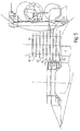
- the attachment 1 is on its front with a Provided with a plurality of guide fingers 2 and divider tips 3, through which the crop does not move as the Harvester shown in the direction of arrow F is carried out first. Then several follow Pick-up elements 4, 5, 6, 7 for recording the crop.
- the front attachment 1 is symmetrical with respect to the central axis built in the direction of travel 11, so that each other corresponding components with the same reference numerals are provided.
- the recording elements comprise different levels of sprocket-like carriers 8, 9, 10, such as in particular with reference to FIGS. 2 and 3. Below this driver 8, 9, 10 is a knife disk 11 arranged, which entering the drivers 8, 9, 10 Crop stalk cuts.
- a cross conveyor 12 consisting of two transverse conveyor segments 13, 14, constructed.
- Guide elements 15, 16, 17 guide the flow of material from the Receiving elements 4, 5, 6, 7 to the cross conveyor segments 13, 14.
- Parallel guides 18, 19 ensure that the Crops on the cross conveyor segments 13, 14.
- Each cross conveyor segment 13, 14 comprises in the form of chains or Belt trained traction means 20, 21 and 22, 23, 24.
- driving elements 25 are attached to the Traction means 20 to 24, driving elements 25 are attached.
- the traction means 20 to 24 run over frustoconical Deflection rollers 26, 27, the axis of rotation 28, 29 through an angle ⁇ or ⁇ is inclined from the vertical.
- a feeder 30 is located behind the cross conveyor 12 indicated feed rollers 31, 32.
- the entire header 1 is rotatable about the axis of rotation 33 on the harvester stored.
- the header 1 works in the following manner. With the Hitting the receiving elements 4 to 7 are the Stems of the crop, for example corn stalks, by means of the knife disc 11 cut and are in the drivers 8, 9, 10 caught. By rotating the receiving elements 4 to 7 the stems are removed sideways and get into the area of the guide elements 15 to 17 the corn stalks in the further rotation of the receiving elements 4 to 7 targeted to the cross conveyor segments 13 to 14.
- the outer receiving element 7 transfers the material flow in an oblique conveying movement to the inner one Receiving element 6 and there with that of the receiving element 6 harvested crop combined into one stream.
- This Gutstrom is fed to the cross conveyor segment 13.
- the one from the Receiving elements 4, 5 conveyed material flows are via the Guide elements 15, 16 fed to the conveyor segment 14.
- the cross conveyor segment 13 comprises two traction means 20, 21 and thus offers the crop two support points, which for the in Outside area of header 1 occurring crop flow is sufficient.
- the cross conveyor segment 14 operates in the area of inside the deflection roller 26 as a deflection conveyor unit or transfer unit in the feeder 30.
- a deflection conveyor unit or transfer unit in the feeder 30 Through the inclined Arrangement of the axis of rotation 28 of this deflection roller 26 is on simple way a height difference (see. Fig. 2 and 3) to Introduction of the crop stem in the feed 30 overcome.
- the conveyor drums 35 to 39 of a cross conveyor 34 rotate in same sense of rotation and can, for example, over a Belt or chain 48 are driven together.
- the conveyor drums 35, 39 can be different be formed.
- the outer Conveyor drums 35, 36 with fewer levels of Driving elements 40 to 47 are provided.
- the angle too the axis of rotation of the individual conveyor drums 36, 39 in relation to the vertical can, depending on the design of the Driving elements 40 to 47 vary.
- the shape the conveyor drums in addition to the cylindrical shape shown have a truncated cone shape, as in the Introduction to the description.
- the shape of the Conveyor drums 35 to 39 can also be different be trained.
- the internal conveyor drum 39 also serves as a deflection and transfer conveyor unit, recommends the advantageous variant with inclined axis of rotation and frustoconical formation, um on the one hand to overcome the difference in height from moving in and on the other hand, the desired feed position of the To accomplish harvest angel.
- front attachments 1 of the type described can be any many receiving elements 4 to 7 are provided. she only need an appropriately dimensioned Cross conveyor 12, 34 on its back. Accordingly can the individual recording elements 4 to 7 with a be provided much smaller diameter than it was previously the case with such attachments, whereby those caught in the carriers 8 to 10 Reduced centrifugal forces acting on plant stem are. Furthermore, with the combination according to the invention of receiving elements 4 to 7 and cross conveyors 12, 34 a almost any working width of an attachment 14 will be realized. Accordingly, it is essential according to the Invention that behind the receiving elements 4 to 7 one of this receiving elements 4 to 7 independent cross conveyor 12, 34 is provided.
Landscapes
- Life Sciences & Earth Sciences (AREA)
- Environmental Sciences (AREA)
- Harvesting Machines For Root Crops (AREA)
Claims (14)
- Outil frontal pour machine agricole de récolte, pour ramasser et transporter des produits de récolte à tiges, avec au moins deux éléments de ramassage disposés transversalement à la direction de déplacement pour ramasser et transporter le produit récolté et au moins un convoyeur de changement de direction disposé derrière les éléments de ramassage pour prendre en charge le produit récolté et l'acheminer vers une alimentation de la machine de récolte, au moins un convoyeur transversal (12, 34) séparé des éléments dé ramassage (4 à 7) étant prévu derrière lesdits éléments de ramassage (4 à 7), vu dans la direction déplacement, pour prendre en charge le produit récolté par les éléments de ramassage (4 à 7) et le transférer dans le convoyeur de changement de direction (26, 39), caractérisé en ce qu'un convoyeur transversal (12) comporte deux ou plusieurs segments de convoyeur transversal (13, 14) et un point de transfert pour le transfert du produit récolté d'un segment de convoyeur transversal (13, 36) au segment de convoyeur transversal (14, 37) suivant.
- Outil frontal selon la revendication 1, caractérisé en ce que le convoyeur de changement de direction (26, 39) dans la région terminale du convoyeur transversal (12 , 34) est intégré à celui-ci.
- Outil frontal selon une des revendications précédentes, caractérisé en ce que le convoyeur transversal (12, 34) comporte des éléments circulant en continu (20 à 24) qui se déplacent sur des roues ou des tambours de renvoi (26, 27) et/ou des éléments tournants (35 à 39) disposés les uns à côté des autres.
- Outil frontal selon une des revendications précédentes, caractérisé en ce qu'il est prévu au moins un axe de rotation incliné dans le convoyeur transversal (12, 34) dans la région du convoyeur de changement de direction (26, 39).
- Outil frontal selon une des revendications précédentes, caractérisé en ce qu'il est prévu des éléments de guidage et/ou de transport (25) dans le convoyeur de changement de direction (26, 39) pour amener le produit récolté d'une position verticale dans une position au moins inclinée ou couchée.
- Outil frontal selon une des revendications précédentes, caractérisé en ce que la circonférence du convoyeur de changement de direction (26, 39) est plus grande dans la région du pied du produit récolté que dans les parties situées plus haut.
- Outil frontal selon une des revendications précédentes, caractérisé en ce que dans un convoyeur transversal (12) avec des éléments circulant en continu, des moyens d'entraínement sans fin (20 à 24) sont disposés dans au moins deux plans parallèles.
- Outil frontal selon une des revendications précédentes, caractérisé en ce que différents segments de convoyeur transversal (13, 14) sont pourvus d'un nombre différent de moyens d'entraínement sans fin (20 à 24).
- Outil frontal selon une des revendications précédentes, caractérisé en ce que les segments de convoyeur transversal (13) plus proches de l'alimentation (30) présentent un nombre de moyens d'entraínement sans fin (22 à 24) plus grand que les segments de convoyeur transversal (14) situés plus à l'extérieur.
- Outil frontal selon une des revendications précédentes, caractérisé en ce que les moyens d'entraínement sans fin (22 à 24) sont des courroies ou des chaínes.
- Outil frontal selon une des revendications précédentes, caractérisé en ce qu'un convoyeur transversal (34) comprend plusieurs tambours de convoyeur (35 à 39) avec des éléments d'entraínement (40 à 47).
- Outil frontal selon une des revendications précédentes, caractérisé en ce que les éléments d'entraínement (40 à 47) d'un tambour de convoyeur (35 à 39) sont disposés coaxialement les uns avec les autres dans plusieurs plans.
- Outil frontal selon une des revendications précédentes, caractérisé en ce qu'au moins le tambour de convoyeur (39) tourné vers l'alimentation (30) est conformé en tronc de cône.
- Outil frontal selon une des revendications précédentes, caractérisé en ce qu'au moins le tambour de convoyeur (39) tourné vers l'alimentation (30) présente un axe de rotation incliné dans la direction de déplacement ou dans la direction transversale.
Applications Claiming Priority (2)
| Application Number | Priority Date | Filing Date | Title |
|---|---|---|---|
| DE19856444 | 1998-12-08 | ||
| DE19856444A DE19856444A1 (de) | 1998-12-08 | 1998-12-08 | Vorsatzgerät für Erntemaschinen |
Publications (2)
| Publication Number | Publication Date |
|---|---|
| EP1008291A1 EP1008291A1 (fr) | 2000-06-14 |
| EP1008291B1 true EP1008291B1 (fr) | 2004-02-25 |
Family
ID=7890283
Family Applications (1)
| Application Number | Title | Priority Date | Filing Date |
|---|---|---|---|
| EP99123632A Expired - Lifetime EP1008291B1 (fr) | 1998-12-08 | 1999-11-27 | Attachement pour machine de récolte |
Country Status (2)
| Country | Link |
|---|---|
| EP (1) | EP1008291B1 (fr) |
| DE (2) | DE19856444A1 (fr) |
Families Citing this family (20)
| Publication number | Priority date | Publication date | Assignee | Title |
|---|---|---|---|---|
| DE50206637D1 (de) | 2001-10-26 | 2006-06-08 | Kemper Gmbh Maschf | Maschine zum Mähen von stängelartigem Erntegut |
| DE10249458B4 (de) | 2001-10-26 | 2010-01-28 | Maschinenfabrik Kemper Gmbh & Co. Kg | Maschine zum Mähen von stängelartigem Erntegut |
| EP1317879B1 (fr) | 2001-12-05 | 2006-12-27 | Maschinenfabrik Kemper GmbH & Co. KG | Machine pour faucher des plantes à tiges |
| DE10222310A1 (de) * | 2001-12-05 | 2003-09-25 | Kemper Gmbh Maschf | Maschine zum Mähen von stängelartigem Erntegut |
| DE10204950A1 (de) * | 2002-02-07 | 2003-09-18 | Kemper Gmbh Maschf | Maschine zum Mähen von stängelartigem Erntegut |
| DE50305564D1 (de) | 2003-04-02 | 2006-12-14 | Kemper Gmbh Maschf | Maschine zum Mähen von stängelartigem Erntegut |
| DE10330669A1 (de) | 2003-07-08 | 2005-02-17 | Maschinenfabrik Kemper Gmbh & Co. Kg | Maschine zum Mähen von stängelartigem Erntegut |
| DE10351858B4 (de) | 2003-11-06 | 2010-04-22 | Maschinenfabrik Kemper Gmbh & Co. Kg | Maschine zum Mähen von stängelartigem Erntegut |
| EP1543714B1 (fr) * | 2003-12-17 | 2011-05-25 | CLAAS Saulgau GmbH | Dispositif de recolte de maize |
| DE10359091B4 (de) * | 2003-12-17 | 2011-05-05 | Maschinenfabrik Kemper Gmbh & Co. Kg | Maschine zum Mähen stängelartigen Ernteguts |
| DE102005004004A1 (de) | 2005-01-27 | 2006-08-17 | Maschinenfabrik Bernard Krone Gmbh | Selbstfahrende landwirtschaftliche Erntemaschine |
| DE102005009939B4 (de) * | 2005-03-04 | 2013-02-07 | Maschinenfabrik Kemper Gmbh & Co. Kg | Erntevorsatz für landwirtschaftliche Erntemaschinen |
| DE102008035191A1 (de) | 2008-07-28 | 2010-02-04 | Claas Saulgau Gmbh | Vorsatzgerät zum Ernten von stängeligem Erntegut |
| DE202008010116U1 (de) | 2008-07-28 | 2009-02-12 | Claas Saulgau Gmbh | Vorsatzgerät zum Ernten von stängeligem Erntegut |
| DE102013212174A1 (de) | 2013-06-26 | 2014-12-31 | Maschinenfabrik Kemper Gmbh & Co. Kg | Maschine zum Mähen von stängelartigem Erntegut mit sukzessive ansteigender Querfördergeschwindigkeit |
| DE102015206845B4 (de) | 2015-04-16 | 2024-08-22 | Maschinenfabrik Kemper Gmbh & Co. Kg | Schneidwerk zur Ganzpflanzenernte |
| ITUB20152931A1 (it) * | 2015-08-06 | 2017-02-06 | Stw S R L | Macchina agricola per la mietitura di una coltura comprendente una barra raccoglitrice ed un sistema di trasporto di detta coltura su detta barra raccoglitrice, e relativo sistema di trasporto |
| DE102022124860A1 (de) | 2022-09-27 | 2024-03-28 | Deere & Company | Erntevorsatz zur Ernte stängelartiger Pflanzen |
| DE102022128070A1 (de) * | 2022-10-24 | 2024-04-25 | Claas Saulgau Gmbh | Maisgebiss für einen Feldhäcksler und Feldhäcksler mit einem solchen Maisgebiss |
| DE102022128071A1 (de) * | 2022-10-24 | 2024-04-25 | Claas Saulgau Gmbh | Maisgebiss für einen Feldhäcksler und Feldhäcksler mit einem solchen Maisgebiss |
Family Cites Families (9)
| Publication number | Priority date | Publication date | Assignee | Title |
|---|---|---|---|---|
| DE2020129A1 (de) * | 1970-04-24 | 1971-11-04 | Brenner Walter Gustav Dr Ing | Feldhaecksler mit einer Mais-Maehvorrichtung |
| AT378890B (de) * | 1978-01-12 | 1985-10-10 | Poettinger Ohg Alois | Vorrichtung zum aufnehmen sowie abtrennen und zum weiterfùhren mehrerer reihen stengeligen erntegutes, insbesondere mais |
| DE3419516A1 (de) * | 1984-05-25 | 1985-11-28 | Alois Pöttinger Landmaschinen-Gesellschaft mbH, 8900 Augsburg | Rotationseinzug fuer feldhaecksler |
| HU201202B (en) * | 1988-03-28 | 1990-10-28 | Bekescsabai Mezoegazdasagi Gep | Wide-cutting harvesting adapter of rough fodder |
| US5040362A (en) * | 1990-06-20 | 1991-08-20 | Morgan Forage Harvesting | Harvesting implement |
| DE4111981A1 (de) | 1991-04-12 | 1992-10-15 | Kemper Gmbh Maschf | Maschine zum maehen und haeckseln von mais und dgl. stengelartigem erntegut |
| NL9101845A (nl) * | 1991-11-05 | 1993-06-01 | Zweegers & Zonen P J | Maishakselaar. |
| DE19531918B4 (de) * | 1995-08-30 | 2005-02-24 | Maschinenfabrik Kemper Gmbh & Co. Kg | Maschine zum reihenunabhängigen Mähen und Häckseln von Mais u. dgl. stengelartigem Erntegut |
| ATE178185T1 (de) * | 1995-09-30 | 1999-04-15 | Kemper Gmbh Maschf | Mähvorrichtung |
-
1998
- 1998-12-08 DE DE19856444A patent/DE19856444A1/de not_active Ceased
-
1999
- 1999-11-27 EP EP99123632A patent/EP1008291B1/fr not_active Expired - Lifetime
- 1999-11-27 DE DE59908639T patent/DE59908639D1/de not_active Expired - Lifetime
Also Published As
| Publication number | Publication date |
|---|---|
| EP1008291A1 (fr) | 2000-06-14 |
| DE19856444A1 (de) | 2000-06-15 |
| DE59908639D1 (de) | 2004-04-01 |
Similar Documents
| Publication | Publication Date | Title |
|---|---|---|
| EP1008291B1 (fr) | Attachement pour machine de récolte | |
| EP0099527B1 (fr) | Faucheuse- hacheuse de mais et autres récoltes, à longue tige, similaires | |
| DE3712507C1 (de) | Maehvorrichtung | |
| EP0508189B1 (fr) | Machine pour faucher et hacher le mais et les plantes à tige similaires | |
| DE19734747B4 (de) | Maisernte-Vorsatz zum Anbau an eine selbstfahrende Erntemaschine | |
| EP1106049B1 (fr) | Dispositif d'introduction et de cueillage avec un dispositif de hachage | |
| EP1106048B1 (fr) | Dispositif d'introduction et de cueillage d'un dispositif de chargement de récoltes | |
| EP2255610B1 (fr) | Tête pour récolter des plantes en forme de tige | |
| DE2848450A1 (de) | Reihenschneid-anbaugeraet | |
| EP1010363B1 (fr) | Machine pour faucher et hacher le mais et les plantes à tiges similaires | |
| EP1106047A1 (fr) | Dispositif d'introduction et de cueillage et machine de récolte | |
| DE4002344C2 (fr) | ||
| DE10153198A1 (de) | Einzugs- und Pflückeinrichtung | |
| EP3007540B1 (fr) | Dispositif à cueillir | |
| EP2545762B1 (fr) | Appareil adaptable pour une moissonneuse-batteuse autotractée destinée à la récolte de produits agricoles en forme de tiges | |
| DE10351858B4 (de) | Maschine zum Mähen von stängelartigem Erntegut | |
| DE10257776A1 (de) | Einzugs- und Pflückeinrichtung | |
| EP1317879A1 (fr) | Machine pour faucher des plantes à tiges | |
| DE10330669A1 (de) | Maschine zum Mähen von stängelartigem Erntegut | |
| EP2923556B1 (fr) | Appareil frontal pour une moissonneuse-batteuse auto-tractée destinée à la récolte de maïs | |
| DE3226876A1 (de) | Maschine zum maehen und haeckseln von mais oder aehnlichem stengelartigen erntegut | |
| DE102013106198A1 (de) | Erntemaschine zum Mähen stängeliger Pflanzen | |
| DE10204950A1 (de) | Maschine zum Mähen von stängelartigem Erntegut | |
| EP1129610B1 (fr) | Dispositif d'introduction et de cueillage pour une machine de récolte | |
| EP0685149A1 (fr) | Machine pour faucher et hacher le mais et les plantes à tige similaires |
Legal Events
| Date | Code | Title | Description |
|---|---|---|---|
| PUAI | Public reference made under article 153(3) epc to a published international application that has entered the european phase |
Free format text: ORIGINAL CODE: 0009012 |
|
| AK | Designated contracting states |
Kind code of ref document: A1 Designated state(s): BE DE FR IT |
|
| AX | Request for extension of the european patent |
Free format text: AL;LT;LV;MK;RO;SI |
|
| 17P | Request for examination filed |
Effective date: 20001214 |
|
| AKX | Designation fees paid |
Free format text: BE DE FR IT |
|
| 17Q | First examination report despatched |
Effective date: 20021107 |
|
| GRAH | Despatch of communication of intention to grant a patent |
Free format text: ORIGINAL CODE: EPIDOS IGRA |
|
| GRAS | Grant fee paid |
Free format text: ORIGINAL CODE: EPIDOSNIGR3 |
|
| GRAA | (expected) grant |
Free format text: ORIGINAL CODE: 0009210 |
|
| AK | Designated contracting states |
Kind code of ref document: B1 Designated state(s): BE DE FR IT |
|
| PG25 | Lapsed in a contracting state [announced via postgrant information from national office to epo] |
Ref country code: IT Free format text: LAPSE BECAUSE OF FAILURE TO SUBMIT A TRANSLATION OF THE DESCRIPTION OR TO PAY THE FEE WITHIN THE PRESCRIBED TIME-LIMIT;WARNING: LAPSES OF ITALIAN PATENTS WITH EFFECTIVE DATE BEFORE 2007 MAY HAVE OCCURRED AT ANY TIME BEFORE 2007. THE CORRECT EFFECTIVE DATE MAY BE DIFFERENT FROM THE ONE RECORDED. Effective date: 20040225 |
|
| REF | Corresponds to: |
Ref document number: 59908639 Country of ref document: DE Date of ref document: 20040401 Kind code of ref document: P |
|
| PGFP | Annual fee paid to national office [announced via postgrant information from national office to epo] |
Ref country code: BE Payment date: 20041008 Year of fee payment: 6 |
|
| ET | Fr: translation filed | ||
| PLBE | No opposition filed within time limit |
Free format text: ORIGINAL CODE: 0009261 |
|
| STAA | Information on the status of an ep patent application or granted ep patent |
Free format text: STATUS: NO OPPOSITION FILED WITHIN TIME LIMIT |
|
| 26N | No opposition filed |
Effective date: 20041126 |
|
| PG25 | Lapsed in a contracting state [announced via postgrant information from national office to epo] |
Ref country code: BE Free format text: LAPSE BECAUSE OF NON-PAYMENT OF DUE FEES Effective date: 20051130 |
|
| BERE | Be: lapsed |
Owner name: *CLAAS SAULGAU G.M.B.H. Effective date: 20051130 |
|
| PGFP | Annual fee paid to national office [announced via postgrant information from national office to epo] |
Ref country code: FR Payment date: 20101130 Year of fee payment: 12 |
|
| REG | Reference to a national code |
Ref country code: FR Ref legal event code: ST Effective date: 20120731 |
|
| PG25 | Lapsed in a contracting state [announced via postgrant information from national office to epo] |
Ref country code: FR Free format text: LAPSE BECAUSE OF NON-PAYMENT OF DUE FEES Effective date: 20111130 |
|
| PGFP | Annual fee paid to national office [announced via postgrant information from national office to epo] |
Ref country code: DE Payment date: 20131121 Year of fee payment: 15 |
|
| REG | Reference to a national code |
Ref country code: DE Ref legal event code: R119 Ref document number: 59908639 Country of ref document: DE |
|
| PG25 | Lapsed in a contracting state [announced via postgrant information from national office to epo] |
Ref country code: DE Free format text: LAPSE BECAUSE OF NON-PAYMENT OF DUE FEES Effective date: 20150602 |