EP1008313A2 - Dispositif de verrouillage à encliquetage - Google Patents
Dispositif de verrouillage à encliquetage Download PDFInfo
- Publication number
- EP1008313A2 EP1008313A2 EP99124570A EP99124570A EP1008313A2 EP 1008313 A2 EP1008313 A2 EP 1008313A2 EP 99124570 A EP99124570 A EP 99124570A EP 99124570 A EP99124570 A EP 99124570A EP 1008313 A2 EP1008313 A2 EP 1008313A2
- Authority
- EP
- European Patent Office
- Prior art keywords
- anchor plate
- slide member
- locking tongue
- wheel
- circumferential portion
- Prior art date
- Legal status (The legal status is an assumption and is not a legal conclusion. Google has not performed a legal analysis and makes no representation as to the accuracy of the status listed.)
- Withdrawn
Links
- 239000000463 material Substances 0.000 claims description 11
- 238000001746 injection moulding Methods 0.000 claims description 5
- 229920002994 synthetic fiber Polymers 0.000 claims description 4
- 238000000926 separation method Methods 0.000 abstract description 3
- 238000010276 construction Methods 0.000 description 3
- 239000002184 metal Substances 0.000 description 3
- 230000003993 interaction Effects 0.000 description 2
- 239000000243 solution Substances 0.000 description 2
- 239000012876 carrier material Substances 0.000 description 1
- 230000005489 elastic deformation Effects 0.000 description 1
- 230000002349 favourable effect Effects 0.000 description 1
- 238000004519 manufacturing process Methods 0.000 description 1
- 239000004753 textile Substances 0.000 description 1
- XLYOFNOQVPJJNP-UHFFFAOYSA-N water Substances O XLYOFNOQVPJJNP-UHFFFAOYSA-N 0.000 description 1
Images



Classifications
-
- F—MECHANICAL ENGINEERING; LIGHTING; HEATING; WEAPONS; BLASTING
- F41—WEAPONS
- F41C—SMALLARMS, e.g. PISTOLS, RIFLES; ACCESSORIES THEREFOR
- F41C33/00—Means for wearing or carrying smallarms
- F41C33/02—Holsters, i.e. cases for pistols having means for being carried or worn, e.g. at the belt or under the arm
- F41C33/04—Special attachments therefor
- F41C33/041—Special attachments therefor for connecting a holster to a belt, webbing or other object
-
- A—HUMAN NECESSITIES
- A44—HABERDASHERY; JEWELLERY
- A44B—BUTTONS, PINS, BUCKLES, SLIDE FASTENERS, OR THE LIKE
- A44B11/00—Buckles; Similar fasteners for interconnecting straps or the like, e.g. for safety belts
- A44B11/25—Buckles; Similar fasteners for interconnecting straps or the like, e.g. for safety belts with two or more separable parts
- A44B11/258—Buckles; Similar fasteners for interconnecting straps or the like, e.g. for safety belts with two or more separable parts fastening by superposing one part on top of the other
- A44B11/2584—Buckles; Similar fasteners for interconnecting straps or the like, e.g. for safety belts with two or more separable parts fastening by superposing one part on top of the other followed by sliding in the main plane of the buckle
-
- A—HUMAN NECESSITIES
- A45—HAND OR TRAVELLING ARTICLES
- A45F—TRAVELLING OR CAMP EQUIPMENT: SACKS OR PACKS CARRIED ON THE BODY
- A45F5/00—Holders or carriers for hand articles; Holders or carriers for use while travelling or camping
- A45F5/02—Fastening articles to the garment
-
- A—HUMAN NECESSITIES
- A45—HAND OR TRAVELLING ARTICLES
- A45F—TRAVELLING OR CAMP EQUIPMENT: SACKS OR PACKS CARRIED ON THE BODY
- A45F5/00—Holders or carriers for hand articles; Holders or carriers for use while travelling or camping
- A45F5/1516—Holders or carriers for portable handheld communication devices, e.g. pagers or smart phones
-
- F—MECHANICAL ENGINEERING; LIGHTING; HEATING; WEAPONS; BLASTING
- F41—WEAPONS
- F41C—SMALLARMS, e.g. PISTOLS, RIFLES; ACCESSORIES THEREFOR
- F41C33/00—Means for wearing or carrying smallarms
- F41C33/02—Holsters, i.e. cases for pistols having means for being carried or worn, e.g. at the belt or under the arm
- F41C33/04—Special attachments therefor
- F41C33/041—Special attachments therefor for connecting a holster to a belt, webbing or other object
- F41C33/045—Special attachments therefor for connecting a holster to a belt, webbing or other object for connection in more than one rotational position around an axle, e.g. by using a rotatable connection
-
- A—HUMAN NECESSITIES
- A45—HAND OR TRAVELLING ARTICLES
- A45F—TRAVELLING OR CAMP EQUIPMENT: SACKS OR PACKS CARRIED ON THE BODY
- A45F5/00—Holders or carriers for hand articles; Holders or carriers for use while travelling or camping
- A45F5/02—Fastening articles to the garment
- A45F2005/025—Fastening articles to the garment with a holder or item rotatably connected to the fastening device, e.g. having a rotation axis perpendicular to the garment
- A45F2005/026—Fastening articles to the garment with a holder or item rotatably connected to the fastening device, e.g. having a rotation axis perpendicular to the garment with a pin having an enlarged head detachably connected to a fastening device, e.g. to a pin receiving slot
Definitions
- the invention relates to a snap-in locking device for securing holding elements for flashlights, mobile telephones, pistol holsters or similar special equipment in special articles of clothing, such as, for example, jackets, vests, trousers for craftsman, police, border guards, watch personnel or the like, with an anchor plate securable to the article of clothing and a slide member movable at the anchor plate from a locking position into an unlocking position approximately parallel to the principal plane of the anchor plate, wherein the slide member is fixedly connected to the holding element.
- the invention is based on the object of further developing the device of the above-mentioned type in such a way that the disadvantages mentioned above are eliminated and an unintentional separation of the slide member with the holding element from the anchor plate is prevented.
- the device according to the invention in which this object is met is essentially characterized in that the anchor plate is provided with a locking tongue which limits the release path for the slide member and includes a stop edge, wherein the locking tongue is elastically deformable into a slide member release position when a force is applied on the locking tongue.
- the slide member When an external force acts on the holding element and, thus, on the slide member, the slide member can move out of the locking position into the unlocking position, wherein the slide member has to overcome a constriction of the slide path. However, the slide member then makes contact with the stop edge of the locking tongue which safely prevents an uncontrolled separation of the slide member from the anchor plate.
- the locking tongue which limits the slide path could be constructed as a structural component of the anchor plate which laterally protrudes into the slide path.
- the locking tongue is constructed in the form of a tab which is elastically deformable transversely of its plane into the locking member release position.
- the slide member could be constructed in the form of a polygon which is mounted in a guide path provided on the anchor plate.
- a solution has been found useful in which the slide member is constructed in the form of a wheel which has a first circumferential portion with a diameter which corresponds to a distance between guide edges which define a middle recess of the anchor plate, and a second circumferential portion which has a comparatively larger diameter and which interacts with the stop edge of the locking tongue which protrudes into the slide path.
- a symmetrical configuration results in a particularly advantageous manner if the anchor plate is formed in the shape of an isosceles triangle of synthetic material and is provided in the areas of the three rounded corners with a recess each which includes a bore each for securing to an article of clothing, for example, by means of a rivet formed, for example, by injection molding.
- a particularly secure snap-in locking device which still facilitates a flat construction, is obtained if the locking tongue with its stop edge extends at a distance from the surface of the anchor plate which ensures that the wheel forming the slide member impinges with its second circumferential portion on the stop edge, and that, on both sides of the guide edges which define the middle recess of the anchor plate and through which the first circumferential portion of the wheel extends, a step is indented in the surface with a width which corresponds at least to the diameter of the second circumferential portion, and with a depth which corresponds at least to the thickness of the second circumferential portion of the wheel minus the distance of the anchor plate surface from the stop edge of the locking tongue, and with a length which ensures that the wheel can be inserted with its second circumferential portion into the step and can be moved parallel to the surface of the anchor plate beyond the stop edge of the locking tongue.
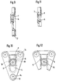
- the snap-in locking device illustrated in the drawing which serves for securing holding elements for flashlights, mobile telephones, pistol holsters or similar special equipment in special articles of clothing, such as, for example, jackets, vests, trousers for craftsmen, police, border guards, watch personnel of the like, includes an anchor plate 1 securable to the article of clothing and a slide member 2 movable approximately parallel to the principal plane of the anchor plate 1, wherein the slide member 2 is fixedly connected to the holding element, not shown, for special equipment.
- the slide member 2 is constructed in the form of a wheel which has a first circumferential portion 3 with a diameter d1 which corresponds to the distance a between guide edges 5 defining a middle recess 4 of the anchor plate 1, i.e., the diameter d1 is somewhat smaller than the distance a. Furthermore, the wheel 2 has a second circumferential portion 6 with a comparatively larger diameter d2.
- This second circumferential portion 6 interacts with the stop edge 7 of a locking tongue 8 protruding into the slide path, wherein the locking tongue 8 is constructed as a fixed structural unit with the anchor plate 1 in the form of a tab which is elastically deformable transversely of its plane in order to reach a released position of the slide member when a force is applied on the tab.
- a constriction 9 is provided in the area of the guide edges 5, wherein the constriction 9 separates the end portion provided in the middle recess 4 of the anchor plate 1, in which the wheel is located when in a locking position, from the adjacent portion in which, after overcoming the constriction, the wheel is located in the unlocking position and could be removed from the anchor plate if the locking tongue 8 with its stop edge 7 would not limit the movement of the wheel.
- a step 10 is indented into the surface on both sides of the guide edges 5 which define the middle recess of the anchor plate 1 and through which the first circumferential portion 3 of the wheel extends.
- the step 10 has a width b which corresponds at least to the diameter d2 of the second circumferential portion 6 of the wheel.
- the step 10 has a depth t which corresponds at least to the width s of the second circumferential portion 6 of the wheel minus the distance c of the anchor plate surface from the stop edge 7 of the locking tongue 8.
- Figs. 13 and 14 show how the anchor plate 1 is secured to the support material 11 in the form of a prefabricated ribbon which can later be sewn to the article of clothing.
- the anchor plate 1 constructed in the form of an isosceles triangle of synthetic material is provided in the areas of the three rounded corners each with a recess 12.
- Each recess 12 has a bore 14 for securing the anchor plate 1 to an article of clothing, for example, by means of a rivet 13 which may also be formed by injection molding.
- the slide member 2 in the form of the wheel which, for securing to the support material of the holding element, is provided with a central bore 15, which serves for receiving a rivet shaft of synthetic material so as to enclose the support material between the wheel and the rivet head. Also in this case, it is possible to provide the rivet connection with the support material by injection molding instead of with a metal rivet.
Landscapes
- Engineering & Computer Science (AREA)
- General Engineering & Computer Science (AREA)
- Slide Fasteners, Snap Fasteners, And Hook Fasteners (AREA)
- Clamps And Clips (AREA)
- Professional, Industrial, Or Sporting Protective Garments (AREA)
- Details Of Garments (AREA)
- Telephone Set Structure (AREA)
Applications Claiming Priority (2)
| Application Number | Priority Date | Filing Date | Title |
|---|---|---|---|
| DE19857318A DE19857318A1 (de) | 1998-12-11 | 1998-12-11 | Rastverschlußvorrichtung |
| DE19857318 | 1998-12-11 |
Publications (2)
| Publication Number | Publication Date |
|---|---|
| EP1008313A2 true EP1008313A2 (fr) | 2000-06-14 |
| EP1008313A3 EP1008313A3 (fr) | 2001-09-26 |
Family
ID=7890821
Family Applications (1)
| Application Number | Title | Priority Date | Filing Date |
|---|---|---|---|
| EP99124570A Withdrawn EP1008313A3 (fr) | 1998-12-11 | 1999-12-09 | Dispositif de verrouillage à encliquetage |
Country Status (3)
| Country | Link |
|---|---|
| EP (1) | EP1008313A3 (fr) |
| DE (1) | DE19857318A1 (fr) |
| TR (1) | TR199903084A3 (fr) |
Cited By (8)
| Publication number | Priority date | Publication date | Assignee | Title |
|---|---|---|---|---|
| WO2003061429A1 (fr) * | 2002-01-24 | 2003-07-31 | Rivet Pty Ltd | Systeme de fixation de dispositif personnel |
| WO2006076753A1 (fr) * | 2005-01-20 | 2006-07-27 | Edgar Lill | Dispositif de port pour une arme a feu de poing |
| GB2457271A (en) * | 2008-02-08 | 2009-08-12 | Stephen Robert Martin | A wallet retention clip |
| WO2021123786A3 (fr) * | 2019-12-19 | 2021-07-22 | Convatec Limited | Supports de courroie pour appareils de stomie |
| USD954546S1 (en) | 2020-06-18 | 2022-06-14 | Vista Outdoor Operations Llc | Attachment device |
| CN114867436A (zh) * | 2019-12-19 | 2022-08-05 | 康沃特克有限公司 | 用于造口术器具的条带安装座 |
| US11781831B2 (en) | 2020-06-12 | 2023-10-10 | Vista Outdoor Operations Llc | Thumb-actuated locking holster system |
| US12295875B2 (en) | 2020-02-20 | 2025-05-13 | Convatec Limited | Ostomy appliance coupling assembly |
Family Cites Families (4)
| Publication number | Priority date | Publication date | Assignee | Title |
|---|---|---|---|---|
| US1428358A (en) * | 1919-09-20 | 1922-09-05 | Walter J Burbery | Fastener |
| US1519380A (en) * | 1924-05-02 | 1924-12-16 | Kochanski Joseph | Garment fastener |
| GB2276658A (en) * | 1993-03-31 | 1994-10-05 | Yih Bai Enterprise Co Ltd | Wireless telephone holder with a belt suspender |
| US5622296A (en) * | 1995-12-06 | 1997-04-22 | Pirhonen; Ilkka | Releasable swivel holder for personal articles |
-
1998
- 1998-12-11 DE DE19857318A patent/DE19857318A1/de not_active Withdrawn
-
1999
- 1999-12-09 EP EP99124570A patent/EP1008313A3/fr not_active Withdrawn
- 1999-12-13 TR TR1999/03084A patent/TR199903084A3/tr unknown
Non-Patent Citations (1)
| Title |
|---|
| None |
Cited By (11)
| Publication number | Priority date | Publication date | Assignee | Title |
|---|---|---|---|---|
| WO2003061429A1 (fr) * | 2002-01-24 | 2003-07-31 | Rivet Pty Ltd | Systeme de fixation de dispositif personnel |
| EP1474015A4 (fr) * | 2002-01-24 | 2008-01-23 | Rivet Pty Ltd | Systeme de fixation de dispositif personnel |
| WO2006076753A1 (fr) * | 2005-01-20 | 2006-07-27 | Edgar Lill | Dispositif de port pour une arme a feu de poing |
| GB2457271A (en) * | 2008-02-08 | 2009-08-12 | Stephen Robert Martin | A wallet retention clip |
| WO2021123786A3 (fr) * | 2019-12-19 | 2021-07-22 | Convatec Limited | Supports de courroie pour appareils de stomie |
| CN114867436A (zh) * | 2019-12-19 | 2022-08-05 | 康沃特克有限公司 | 用于造口术器具的条带安装座 |
| JP2023511498A (ja) * | 2019-12-19 | 2023-03-20 | コンバテック リミティド | ストーマ装具用ベルトマウント |
| US12295875B2 (en) | 2020-02-20 | 2025-05-13 | Convatec Limited | Ostomy appliance coupling assembly |
| US11781831B2 (en) | 2020-06-12 | 2023-10-10 | Vista Outdoor Operations Llc | Thumb-actuated locking holster system |
| USD954546S1 (en) | 2020-06-18 | 2022-06-14 | Vista Outdoor Operations Llc | Attachment device |
| USD996961S1 (en) | 2020-06-18 | 2023-08-29 | Vista Outdoor Operations Llc | Attachment device |
Also Published As
| Publication number | Publication date |
|---|---|
| TR199903084A2 (xx) | 2001-07-23 |
| DE19857318A1 (de) | 2000-06-15 |
| EP1008313A3 (fr) | 2001-09-26 |
| TR199903084A3 (tr) | 2001-07-23 |
Similar Documents
| Publication | Publication Date | Title |
|---|---|---|
| US4727630A (en) | Plastic buckle | |
| EP0570814B1 (fr) | Dispositif de blocage de corde | |
| US5850954A (en) | Holder assembly for cellular phones | |
| US5564166A (en) | Badge clip assembly including a spring-biased clip member | |
| JP3240559B2 (ja) | バックル・アセンブリ | |
| EP1262115A3 (fr) | Curseur pour fermeture à glissière incluant un dispositif de verrouillage | |
| JPH0650514U (ja) | スライドファスナー用スライダーの引手連結具および挟持止具 | |
| CA2107247A1 (fr) | Dispositif de fixation a pression | |
| JPH0591905A (ja) | バツクル | |
| EP3648627A1 (fr) | Système de fixation | |
| US4107823A (en) | Belt holding clips, particularly for keys, tools and the like | |
| CN109152454A (zh) | 绳扣 | |
| WO2019186665A1 (fr) | Boucle | |
| EP1236413A3 (fr) | Butée d'arrêt supérieure pour fermeture à glissière | |
| US20200288806A1 (en) | Attachment system | |
| EP1247704A3 (fr) | Boucle de ceinture de sécurité avec détecteur de tension | |
| US10070713B1 (en) | Clip holder for holding a tape measure and other tools | |
| GB1578302A (en) | Adjustable fastening device | |
| EP1020651A3 (fr) | Elément de fixation à saillies de retenue et saillies de prépositionnement de la goupille | |
| JP3476150B2 (ja) | 装身具用ピンの係止機構 | |
| US6647599B2 (en) | Positioning mechanism of a zipper slide | |
| EP1008313A3 (fr) | Dispositif de verrouillage à encliquetage | |
| HK126497A (en) | Fastener assembly | |
| US4847955A (en) | Key holder | |
| US7117566B1 (en) | Manually releasable clip holder |
Legal Events
| Date | Code | Title | Description |
|---|---|---|---|
| PUAI | Public reference made under article 153(3) epc to a published international application that has entered the european phase |
Free format text: ORIGINAL CODE: 0009012 |
|
| AK | Designated contracting states |
Kind code of ref document: A2 Designated state(s): AT BE CH CY DE DK ES FI FR GB GR IE IT LI LU MC NL PT SE |
|
| AX | Request for extension of the european patent |
Free format text: AL;LT;LV;MK;RO;SI |
|
| PUAL | Search report despatched |
Free format text: ORIGINAL CODE: 0009013 |
|
| AK | Designated contracting states |
Kind code of ref document: A3 Designated state(s): AT BE CH CY DE DK ES FI FR GB GR IE IT LI LU MC NL PT SE |
|
| AX | Request for extension of the european patent |
Free format text: AL;LT;LV;MK;RO;SI |
|
| AKX | Designation fees paid | ||
| REG | Reference to a national code |
Ref country code: DE Ref legal event code: 8566 |
|
| STAA | Information on the status of an ep patent application or granted ep patent |
Free format text: STATUS: THE APPLICATION IS DEEMED TO BE WITHDRAWN |
|
| 18D | Application deemed to be withdrawn |
Effective date: 20020327 |