EP1008421A2 - Outil à main électrique - Google Patents
Outil à main électrique Download PDFInfo
- Publication number
- EP1008421A2 EP1008421A2 EP99811100A EP99811100A EP1008421A2 EP 1008421 A2 EP1008421 A2 EP 1008421A2 EP 99811100 A EP99811100 A EP 99811100A EP 99811100 A EP99811100 A EP 99811100A EP 1008421 A2 EP1008421 A2 EP 1008421A2
- Authority
- EP
- European Patent Office
- Prior art keywords
- supply cable
- handle
- hook part
- handheld device
- cylindrical
- Prior art date
- Legal status (The legal status is an assumption and is not a legal conclusion. Google has not performed a legal analysis and makes no representation as to the accuracy of the status listed.)
- Granted
Links
Images

Classifications
-
- B—PERFORMING OPERATIONS; TRANSPORTING
- B25—HAND TOOLS; PORTABLE POWER-DRIVEN TOOLS; MANIPULATORS
- B25B—TOOLS OR BENCH DEVICES NOT OTHERWISE PROVIDED FOR, FOR FASTENING, CONNECTING, DISENGAGING OR HOLDING
- B25B21/00—Portable power-driven screw or nut setting or loosening tools; Attachments for drilling apparatus serving the same purpose
-
- B—PERFORMING OPERATIONS; TRANSPORTING
- B25—HAND TOOLS; PORTABLE POWER-DRIVEN TOOLS; MANIPULATORS
- B25F—COMBINATION OR MULTI-PURPOSE TOOLS NOT OTHERWISE PROVIDED FOR; DETAILS OR COMPONENTS OF PORTABLE POWER-DRIVEN TOOLS NOT PARTICULARLY RELATED TO THE OPERATIONS PERFORMED AND NOT OTHERWISE PROVIDED FOR
- B25F5/00—Details or components of portable power-driven tools not particularly related to the operations performed and not otherwise provided for
-
- B—PERFORMING OPERATIONS; TRANSPORTING
- B25—HAND TOOLS; PORTABLE POWER-DRIVEN TOOLS; MANIPULATORS
- B25H—WORKSHOP EQUIPMENT, e.g. FOR MARKING-OUT WORK; STORAGE MEANS FOR WORKSHOPS
- B25H3/00—Storage means or arrangements for workshops facilitating access to, or handling of, work tools or instruments
- B25H3/006—Storage means specially adapted for one specific hand apparatus, e.g. an electric drill
-
- H—ELECTRICITY
- H02—GENERATION; CONVERSION OR DISTRIBUTION OF ELECTRIC POWER
- H02G—INSTALLATION OF ELECTRIC CABLES OR LINES, OR OF COMBINED OPTICAL AND ELECTRIC CABLES OR LINES
- H02G11/00—Arrangements of electric cables or lines between relatively-movable parts
Definitions
- the invention relates to an electrically operated handheld device, in particular an electric screwdriver and / or a drilling device according to the preamble of claim 1.
- Electrically operated handheld devices in particular electric screwdrivers, drilling devices, Combi devices and the like have an electrical supply cable that is usually passed through an opening in the handle area.
- a kink protection sleeve is provided, which is in the lead-through area for the cable the housing or handle scales is fixed. Because of the constant kinking movements the supply cable protruding from the housing when working with the handheld device is subject to breakage of the strands in the connection cable despite the kink protection sleeve come. This leads to the handset coming to a standstill and requires an exchange of the Supply cable.
- an electrically operated handheld device for example one Electric screwdriver or a drill
- an electrically operated handheld device for example one Electric screwdriver or a drill
- the handheld device there is always a need for that Put the handheld device out of your hand to unhindered both hands for other activities to be able to use. It can also be used, for example, during assembly work on a Scaffolding or on a ladder may be necessary from the scaffolding or the ladder at short notice climb, for example to get more screws or to get the ladder into the desired position to move.
- the problem for the user is that Put down the electric screwdriver or the drill and secure it against falling.
- the electrical supply cable for the electric screwdriver or the Drill wrapped around a spar of the scaffold or ladder. It is immediate realizes that such a measure is unsuitable and rather the danger of Cable breaks increased.
- the object of the present invention is therefore an electrically operated hand-held device to be improved in such a way that the device can be stored safely if necessary becomes. At the same time, the risk of network line breaks should be reduced.
- the solution to these tasks is an electrically operated hand-held device that has in the characterizing section of claim 1 features.
- a connection device By adjacent to the opening for the supply cable on the outside of the handle a connection device is provided, can be attached to the device housing, especially on the handle, a hook-shaped curved suspension device are connected, which are held captive on the supply cable and on anywhere in the supply cable can be determined.
- the with the device housing or hanging device releasably connected to the handle fulfills two functions. On the one hand, it enables the handheld device to be connected, for example, to a Scaffolding strut or hanging on a ladder rung. On the other hand, it fulfills the Handle connected, hook-shaped suspension device for the supply cable Support function.
- the hook-shaped The suspension device is held captive on the supply cable and on any The position of the cable can be determined by clamping. It also offers the possibility of Suspension device in a section between the handle of the handheld device and the connector.
- the hook-shaped suspension device can then serve, for example, the hanging supply cable on a suitable Place to hang. For example, this may be desirable to prevent the supply cable comes to rest in a puddle.
- the hanger By the hanger held captive and freely movable along the supply cable, it can when storing the hanging device in a transport case, which is usually relative tightly dimensioned and primarily geared to the device housing dimensions, be moved to a point on the supply cable where they can be easily Transport case can be accommodated. After removing the handset from the Carrying case can be pushed back the hanger and with the Connection device can be connected to the handle.
- the suspension device has a hook part and one on it subsequent, essentially cylindrical connector with a feedthrough for the supply cable.
- the inside diameter of the bushing is at least can be reduced in some areas with the aid of a clamping lever.
- the clamping lever is on cylindrical connecting part is articulated and has a protruding into the bushing Eccentric element on.
- the suspension device designed in this way is with one hand accessible and operable. It is with the help of the clamping lever at any point on the Supply cable can be determined.
- the eccentric reduces the inside diameter of the Carrying out the suspension device against one to a sufficient extent automatic shifting, for example by the weight of the hanging Secure cable.
- the clamping is only so strong that the supply cable is not damaged in the pinched area.
- this is Eccentric element arranged on the pivot axis of the clamping lever.
- the pivot axis of the clamping lever is on the cylindrical connector Suspension device can be moved into two storage positions, which differ in the distance Implementation protrude.
- the two storage positions are through a sliding slot interconnected, which preferably has a slightly smaller slot width than the diameter of the axis brackets of the swivel axis, so that the axle brackets cannot slip automatically.
- the hook part of the suspension device is provided with an outer surface, the one has trough-like depression.
- the trough-like depression extends from the hook part adjacent cylindrical connector over a large part of the Longitudinal extension of the hook part.
- the trough-like depression on the outer surface of the The hook part forms a guide for that which is supported on the suspension device Supply cable. This will result in normal operation of the handheld device Relative swiveling of the handheld device better carried the supply cable. On in this way kinking movements of the cable can be avoided.
- the span is in a particularly advantageous embodiment of the invention the hook part of the suspension device changeable.
- the Hook part can be telescopically pulled apart.
- the hook part can be changed with regard to its curvature.
- This is the hook part For example, divided into individual segments, which have snap-in articulated connections are interconnected.
- the hook part can be made of a plastic exist that is plastically deformable by applying a minimum force.
- connection device on the handle can, for example, in the manner of a Dovetail guide can be formed with corresponding counterparts cooperates on the suspension device.
- connection device of a in formed essentially cylindrical collar which is the passage opening for the Supply cable protrudes from the outside of the handle.
- the cylindrical collar is advantageously formed integrally with the handle shell.
- the suspension device on the device housing becomes its cylindrical connecting part simply pushed over the collar and releasably locked with the clamping lever.
- Wells formed which are preferably at a regular angular distance of are arranged about 60 ° or 90 ° along the circumference of the collar.
- the wells serve as a positive receptacle for the eccentric element on the clamping lever.
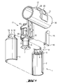
- the reference numeral 1 designates the handle one not in detail shown, electrically operated handheld device, for example an electric screwdriver and / or a drill.
- the handle 1 can, for example, be integral Device housing be molded. In many cases, the handle 1 is also a separate part is screwed to the device housing.
- the handle 1 is usually composed of two handle shells 2, 3, on which Recesses are provided, which in the assembled state have a passage opening 4 for an electrical supply cable, which is usually guided in an anti-kink sleeve 6 40 (Fig. 3) form.
- the provided with a hole 7 for the supply cable Kink protection sleeve 6 is form-fitting in retaining recesses 5 in the handle scales 2, 3 held.
- semi-cylindrical ones protrude from the grip shells Extensions from.
- the extensions form one cylindrical collar 9 which surrounds the passage opening 4.
- the cylindrical collar 9 forms a connection device 8 for a suspension device 11, which consists of a hook part 12 and an adjoining, in essential cylindrical connector 13 with a bushing 14 for the kink protection sleeve 6 or the supply cable 40 is made.
- the inside diameter of the Implementation 14 in the cylindrical connecting part 13 is dimensioned such that the Suspension device 11 can be moved along supply cable 40 as required is and is still held captive.
- To fix the suspension device 11 are in pairs on the frame-shaped, cylindrical connecting part 13 opposite bearing positions 18, 19 recessed, the storage of a Serve pivot axis 16 of a clamping lever 15.
- the bearing positions 18, 19 are of this type arranged that the pivot axis 16 more or less far into the opening cross-section the implementation 14 is displaceable.
- the two storage positions 18, 19 are one Sliding slot 20 connected to each other.
- the slot width is slightly smaller than the outside diameter of the axle brackets.
- depressions 10 are provided, which in an angular distance of, for example, about 60 ° or 90 ° on the circumference of the collar 9 are arranged.
- the recesses 10 serve as a positive receptacle for the Pivot axis 16 of the clamping lever 15 arranged eccentric element 17.
- This is the suspension device 11 can be fixed in a defined angular position on the handle 1.
- a trough-like depression 22 is provided on the outside surface 21 of the hook part 12.
- the recess 22 extends from the cylindrical connecting part 13 over a large part of the Longitudinal extension of the outer surface 21 of the hook part 12.
- the trough-like depression 22 serves to better guide and support the supply cable 40, as shown in FIG. 1 is indicated.
- the hook part 12 of the suspension device 11 is, for example, in a ladder rung or can be hooked into a strut of a scaffold, each with the reference symbol in FIGS. 1-3 30 is indicated.
- groove-like depressions 23 are provided, which are substantially perpendicular to Longitudinal extension of the hook part 12 run.
- the groove-like depressions 23 improve the hold of the suspension device 11 by being in existing bumps or in existing grooves on a strut, a rung or the like Intervene counterpart.
- the groove-like depressions 23 also allow the Suspension 11, for example on a bar or eyelet with a much smaller one Mount diameter as the hook size, and prevent the handheld device falls down.
- the hook width of the hook part 12 changeable and adaptable to the respective conditions.
- the hook part can be telescopically extended.
- the hook part consists of individual segments, which over lockable joints are interconnected.
- the hook part can also be plastic deformable material, which only with a minimum force is deformable, which is greater than the weight of the suspended handheld device.
Landscapes
- Engineering & Computer Science (AREA)
- Mechanical Engineering (AREA)
- Clamps And Clips (AREA)
- Workshop Equipment, Work Benches, Supports, Or Storage Means (AREA)
- Surgical Instruments (AREA)
- Brushes (AREA)
- Arrangements For Transmission Of Measured Signals (AREA)
- Portable Power Tools In General (AREA)
- Connection Of Motors, Electrical Generators, Mechanical Devices, And The Like (AREA)
- Drilling And Boring (AREA)
- Load-Engaging Elements For Cranes (AREA)
- Grinding-Machine Dressing And Accessory Apparatuses (AREA)
- Finish Polishing, Edge Sharpening, And Grinding By Specific Grinding Devices (AREA)
- Installation Of Indoor Wiring (AREA)
- Seal Device For Vehicle (AREA)
- Switches With Compound Operations (AREA)
- Arrangement Or Mounting Of Control Devices For Change-Speed Gearing (AREA)
Applications Claiming Priority (2)
| Application Number | Priority Date | Filing Date | Title |
|---|---|---|---|
| DE19856266 | 1998-12-07 | ||
| DE19856266A DE19856266A1 (de) | 1998-12-07 | 1998-12-07 | Elektrisch betreibbares Handgerät |
Publications (3)
| Publication Number | Publication Date |
|---|---|
| EP1008421A2 true EP1008421A2 (fr) | 2000-06-14 |
| EP1008421A3 EP1008421A3 (fr) | 2003-09-17 |
| EP1008421B1 EP1008421B1 (fr) | 2007-07-25 |
Family
ID=7890161
Family Applications (1)
| Application Number | Title | Priority Date | Filing Date |
|---|---|---|---|
| EP99811100A Expired - Lifetime EP1008421B1 (fr) | 1998-12-07 | 1999-11-30 | Outil à main électrique |
Country Status (9)
| Country | Link |
|---|---|
| US (1) | US6230367B1 (fr) |
| EP (1) | EP1008421B1 (fr) |
| JP (1) | JP4676044B2 (fr) |
| AT (1) | ATE367896T1 (fr) |
| AU (1) | AU752745B2 (fr) |
| CA (1) | CA2290884C (fr) |
| DE (2) | DE19856266A1 (fr) |
| ES (1) | ES2288009T3 (fr) |
| NO (1) | NO311754B1 (fr) |
Families Citing this family (30)
| Publication number | Priority date | Publication date | Assignee | Title |
|---|---|---|---|---|
| US20020117531A1 (en) * | 2001-02-07 | 2002-08-29 | Schell Craig A. | Fastener tool |
| US6612476B2 (en) | 2002-01-14 | 2003-09-02 | Illinois Tool Works Inc. | Fastener driving tool with modular construction |
| US8556148B2 (en) | 2002-01-24 | 2013-10-15 | Black & Decker Inc. | Fastener tool |
| US6722549B2 (en) * | 2002-05-08 | 2004-04-20 | Yury Shkolnikov | Arm member for fastener driving tool |
| US6732627B2 (en) * | 2002-08-22 | 2004-05-11 | Black & Decker Inc. | Carrying mechanism for power tools |
| US20040139835A1 (en) * | 2003-12-22 | 2004-07-22 | Stuart Wright | Band saw with bumpers |
| US20040148786A1 (en) * | 2003-12-22 | 2004-08-05 | Achterberg Nicholas E. | Band saw hook |
| US7306052B2 (en) * | 2004-10-05 | 2007-12-11 | Illinois Tool Works Inc. | Multi-position utility hook assembly for tool |
| US7198188B2 (en) * | 2004-12-14 | 2007-04-03 | Laboratoire Primatech Inc. | Hardwood flooring nailer having an adjustable double handle |
| FR2883217B1 (fr) * | 2005-03-18 | 2007-06-29 | Prospection Et D Inv S Techniq | Appareil a main a poignee de prehension |
| US7231990B2 (en) * | 2005-05-16 | 2007-06-19 | Basso Industry Corp. | Limit structure for a hook of a pneumatic tool |
| US7318487B2 (en) * | 2005-11-07 | 2008-01-15 | Besco Pneumatic Corp. | Pneumatic tool with an adjustable clip |
| USD572563S1 (en) | 2006-03-09 | 2008-07-08 | Black & Decker Inc. | Auxiliary handle for a reciprocating saw |
| US20070209162A1 (en) * | 2006-03-09 | 2007-09-13 | Mcroberts Jason | Auxiliary handle for reciprocating saw |
| USD558018S1 (en) | 2006-03-09 | 2007-12-25 | Black & Decker Inc. | Reciprocating saw |
| JP4844831B2 (ja) | 2006-11-24 | 2011-12-28 | 日立工機株式会社 | 動力工具 |
| JP4844833B2 (ja) * | 2006-11-24 | 2011-12-28 | 日立工機株式会社 | 動力工具 |
| JP5446169B2 (ja) * | 2008-08-22 | 2014-03-19 | 横浜ゴム株式会社 | タイヤ組付け補助具及びそれを用いたタイヤ組付け方法 |
| DE102009017457A1 (de) | 2009-04-06 | 2010-10-07 | C. & E. Fein Gmbh | Zubehörteil für eine handgehaltene Werkzeugmaschine |
| US20120192540A1 (en) * | 2011-01-31 | 2012-08-02 | Macyszyn Witold S | Handle attachment for tools having an elongated shaft |
| US8998057B2 (en) | 2011-08-19 | 2015-04-07 | Techtronic Power Tools Technology Limited | Hook assembly for use with a power tool |
| US9457461B2 (en) * | 2013-08-06 | 2016-10-04 | Robert Bosch Tool Corporation | Dual axis hook assembly for a power tool |
| US9423070B2 (en) * | 2014-04-14 | 2016-08-23 | Wasp Manufacturing Ltd. | Gutter-anchored structure for portable fire sprinklers |
| CN104466598B (zh) * | 2014-11-25 | 2017-01-18 | 宁波江丰生物信息技术有限公司 | 一种用于固定线缆的装置 |
| DE102014225328A1 (de) * | 2014-12-09 | 2016-06-09 | Robert Bosch Gmbh | Werkzeugmaschinengehäusevorrichtung |
| US10215219B1 (en) * | 2018-02-06 | 2019-02-26 | Jeremiah Morley | Multi-function tool and handle hook |
| DE102018104670A1 (de) * | 2018-03-01 | 2019-09-05 | Volkswagen Aktiengesellschaft | Greifvorrichtung für ein Objekt, Laderoboter mit Greifvorrichtung |
| CN108761373B (zh) * | 2018-08-13 | 2024-03-19 | 广东电网有限责任公司 | 测试器 |
| US12404645B2 (en) * | 2022-03-22 | 2025-09-02 | Lisa Johnson | Canine feces rake device |
| US20250235890A1 (en) * | 2024-01-18 | 2025-07-24 | Albion Engineering Company | Structures for retaining accessory tools to a dispensing device |
Family Cites Families (6)
| Publication number | Priority date | Publication date | Assignee | Title |
|---|---|---|---|---|
| US2496612A (en) * | 1946-03-22 | 1950-02-07 | Black & Decker Mfg Co | Suspension device |
| US4247140A (en) * | 1979-08-07 | 1981-01-27 | Gordon Jing R | Universal tool |
| US4369487A (en) * | 1980-09-15 | 1983-01-18 | Carico Corporation | Utility lamp |
| US5172773A (en) * | 1991-04-15 | 1992-12-22 | Ingersoll-Rand Company | Power cord diverter and suspension clamp for a power tool |
| JPH08252784A (ja) * | 1995-03-15 | 1996-10-01 | Makita Corp | 携帯用工具のフック |
| US5810225A (en) * | 1996-11-26 | 1998-09-22 | Andrew; Richard J. | Tool support apparatus |
-
1998
- 1998-12-07 DE DE19856266A patent/DE19856266A1/de not_active Withdrawn
-
1999
- 1999-11-17 AU AU59501/99A patent/AU752745B2/en not_active Ceased
- 1999-11-25 CA CA002290884A patent/CA2290884C/fr not_active Expired - Fee Related
- 1999-11-30 DE DE59914426T patent/DE59914426D1/de not_active Expired - Lifetime
- 1999-11-30 ES ES99811100T patent/ES2288009T3/es not_active Expired - Lifetime
- 1999-11-30 AT AT99811100T patent/ATE367896T1/de active
- 1999-11-30 EP EP99811100A patent/EP1008421B1/fr not_active Expired - Lifetime
- 1999-12-01 US US09/452,301 patent/US6230367B1/en not_active Expired - Lifetime
- 1999-12-06 NO NO19995990A patent/NO311754B1/no not_active IP Right Cessation
- 1999-12-06 JP JP34585899A patent/JP4676044B2/ja not_active Expired - Fee Related
Also Published As
| Publication number | Publication date |
|---|---|
| CA2290884C (fr) | 2007-11-20 |
| ES2288009T3 (es) | 2007-12-16 |
| EP1008421A3 (fr) | 2003-09-17 |
| DE19856266A1 (de) | 2000-06-08 |
| NO995990D0 (no) | 1999-12-06 |
| DE59914426D1 (de) | 2007-09-06 |
| AU5950199A (en) | 2000-06-08 |
| NO995990L (no) | 2000-06-08 |
| AU752745B2 (en) | 2002-09-26 |
| US6230367B1 (en) | 2001-05-15 |
| NO311754B1 (no) | 2002-01-21 |
| EP1008421B1 (fr) | 2007-07-25 |
| JP2000176862A (ja) | 2000-06-27 |
| CA2290884A1 (fr) | 2000-06-07 |
| ATE367896T1 (de) | 2007-08-15 |
| JP4676044B2 (ja) | 2011-04-27 |
Similar Documents
| Publication | Publication Date | Title |
|---|---|---|
| EP1008421B1 (fr) | Outil à main électrique | |
| DE68924820T2 (de) | Flexible Schaftverlängerung für Schraubendreher. | |
| EP1163986A2 (fr) | Dispositif de fixation d'un tuyau de guidage de câbles | |
| EP0379834A1 (fr) | Dispositif d'accouplement, notamment pour disperseur | |
| DE3937928A1 (de) | Reinigungsgeraet zur reinigung eines rundprofiles, insbesondere eines seiles | |
| DE69018097T2 (de) | Handwerkzeug mit zusatzhandgriff. | |
| EP0450135A1 (fr) | Perceuse pour l'élimination des points de soudage | |
| DE2448877A1 (de) | Teleskopartig ausziehbarer stiel mit einem mit dem stiel loesbar verbundenen halter fuer ein werkzeug | |
| DE10243435B4 (de) | Klettergerät für Auf- und Abseilvorgänge | |
| DE3626805C2 (de) | Hubeinrichtung | |
| DE202004000243U1 (de) | Zange | |
| DE19751579C2 (de) | Stabrüttler mit veränderbarer Länge | |
| DE10128337A1 (de) | Vorrichtung zum Bereistellen und Aufbewahren eines flexiblen Mittels | |
| DE2636457C3 (de) | Mastgelenk für ein Segelbrett | |
| DE60214822T2 (de) | Halterungssystem für eine Verlängerungsschnur | |
| DE102024113801B3 (de) | Drahtabzieher | |
| DE2749718B2 (de) | In den Boden eingelassene, als Rohrhülse ausgebildete Steckbuchse | |
| DE19928731C2 (de) | Vorrichtung zum Auf-, Abwickeln und Aufbewahren von länglichen flexiblen Teilen | |
| DE102007013643A1 (de) | Zugentlastung eines Kabels für ein elektromotorisch betriebenes, handgeführtes Arbeitsgerät | |
| DE29811997U1 (de) | Einstiegshilfe zur raschen Kopplung an Einstiegsstellen sowie zum sicheren Ein- und Ausstieg aus denselben | |
| EP4245468A1 (fr) | Poignée latérale pour une machine-outil portative électrique | |
| EP4538495A1 (fr) | Manivelle d'entraînement pour systèmes de rétraction de bâches | |
| EP2664411A2 (fr) | Dispositif de soudage portable | |
| DE8412779U1 (de) | Halterung für Steckdosen | |
| DE1213022B (de) | Seilfuehrungsrollen zum Verlegen von Freileitungen |
Legal Events
| Date | Code | Title | Description |
|---|---|---|---|
| PUAI | Public reference made under article 153(3) epc to a published international application that has entered the european phase |
Free format text: ORIGINAL CODE: 0009012 |
|
| AK | Designated contracting states |
Kind code of ref document: A2 Designated state(s): AT BE CH CY DE DK ES FI FR GB GR IE IT LI LU MC NL PT SE |
|
| AX | Request for extension of the european patent |
Free format text: AL;LT;LV;MK;RO;SI |
|
| PUAL | Search report despatched |
Free format text: ORIGINAL CODE: 0009013 |
|
| AK | Designated contracting states |
Kind code of ref document: A3 Designated state(s): AT BE CH CY DE DK ES FI FR GB GR IE IT LI LU MC NL PT SE |
|
| AX | Request for extension of the european patent |
Extension state: AL LT LV MK RO SI |
|
| 17P | Request for examination filed |
Effective date: 20040317 |
|
| AKX | Designation fees paid |
Designated state(s): AT BE CH CY DE DK ES FI FR GB GR IE IT LI LU MC NL PT SE |
|
| 17Q | First examination report despatched |
Effective date: 20041215 |
|
| GRAP | Despatch of communication of intention to grant a patent |
Free format text: ORIGINAL CODE: EPIDOSNIGR1 |
|
| GRAS | Grant fee paid |
Free format text: ORIGINAL CODE: EPIDOSNIGR3 |
|
| GRAA | (expected) grant |
Free format text: ORIGINAL CODE: 0009210 |
|
| AK | Designated contracting states |
Kind code of ref document: B1 Designated state(s): AT BE CH CY DE DK ES FI FR GB GR IE IT LI LU MC NL PT SE |
|
| REG | Reference to a national code |
Ref country code: GB Ref legal event code: FG4D Free format text: NOT ENGLISH |
|
| REG | Reference to a national code |
Ref country code: CH Ref legal event code: EP |
|
| REG | Reference to a national code |
Ref country code: IE Ref legal event code: FG4D Free format text: LANGUAGE OF EP DOCUMENT: GERMAN |
|
| REF | Corresponds to: |
Ref document number: 59914426 Country of ref document: DE Date of ref document: 20070906 Kind code of ref document: P |
|
| GBT | Gb: translation of ep patent filed (gb section 77(6)(a)/1977) |
Effective date: 20070905 |
|
| REG | Reference to a national code |
Ref country code: SE Ref legal event code: TRGR |
|
| ET | Fr: translation filed | ||
| REG | Reference to a national code |
Ref country code: ES Ref legal event code: FG2A Ref document number: 2288009 Country of ref document: ES Kind code of ref document: T3 |
|
| PG25 | Lapsed in a contracting state [announced via postgrant information from national office to epo] |
Ref country code: PT Free format text: LAPSE BECAUSE OF FAILURE TO SUBMIT A TRANSLATION OF THE DESCRIPTION OR TO PAY THE FEE WITHIN THE PRESCRIBED TIME-LIMIT Effective date: 20071226 Ref country code: NL Free format text: LAPSE BECAUSE OF FAILURE TO SUBMIT A TRANSLATION OF THE DESCRIPTION OR TO PAY THE FEE WITHIN THE PRESCRIBED TIME-LIMIT Effective date: 20070725 |
|
| NLV1 | Nl: lapsed or annulled due to failure to fulfill the requirements of art. 29p and 29m of the patents act | ||
| REG | Reference to a national code |
Ref country code: IE Ref legal event code: FD4D |
|
| PG25 | Lapsed in a contracting state [announced via postgrant information from national office to epo] |
Ref country code: GR Free format text: LAPSE BECAUSE OF FAILURE TO SUBMIT A TRANSLATION OF THE DESCRIPTION OR TO PAY THE FEE WITHIN THE PRESCRIBED TIME-LIMIT Effective date: 20071026 Ref country code: DK Free format text: LAPSE BECAUSE OF FAILURE TO SUBMIT A TRANSLATION OF THE DESCRIPTION OR TO PAY THE FEE WITHIN THE PRESCRIBED TIME-LIMIT Effective date: 20070725 |
|
| PG25 | Lapsed in a contracting state [announced via postgrant information from national office to epo] |
Ref country code: IE Free format text: LAPSE BECAUSE OF FAILURE TO SUBMIT A TRANSLATION OF THE DESCRIPTION OR TO PAY THE FEE WITHIN THE PRESCRIBED TIME-LIMIT Effective date: 20070725 |
|
| PLBE | No opposition filed within time limit |
Free format text: ORIGINAL CODE: 0009261 |
|
| STAA | Information on the status of an ep patent application or granted ep patent |
Free format text: STATUS: NO OPPOSITION FILED WITHIN TIME LIMIT |
|
| BERE | Be: lapsed |
Owner name: HILTI AKTIENGESELLSCHAFT Effective date: 20071130 |
|
| PG25 | Lapsed in a contracting state [announced via postgrant information from national office to epo] |
Ref country code: MC Free format text: LAPSE BECAUSE OF NON-PAYMENT OF DUE FEES Effective date: 20071130 |
|
| 26N | No opposition filed |
Effective date: 20080428 |
|
| PG25 | Lapsed in a contracting state [announced via postgrant information from national office to epo] |
Ref country code: BE Free format text: LAPSE BECAUSE OF NON-PAYMENT OF DUE FEES Effective date: 20071130 |
|
| PG25 | Lapsed in a contracting state [announced via postgrant information from national office to epo] |
Ref country code: CY Free format text: LAPSE BECAUSE OF FAILURE TO SUBMIT A TRANSLATION OF THE DESCRIPTION OR TO PAY THE FEE WITHIN THE PRESCRIBED TIME-LIMIT Effective date: 20070725 |
|
| PG25 | Lapsed in a contracting state [announced via postgrant information from national office to epo] |
Ref country code: LU Free format text: LAPSE BECAUSE OF NON-PAYMENT OF DUE FEES Effective date: 20071130 |
|
| PG25 | Lapsed in a contracting state [announced via postgrant information from national office to epo] |
Ref country code: IT Free format text: LAPSE BECAUSE OF NON-PAYMENT OF DUE FEES Effective date: 20071130 |
|
| PGFP | Annual fee paid to national office [announced via postgrant information from national office to epo] |
Ref country code: FR Payment date: 20131108 Year of fee payment: 15 Ref country code: CH Payment date: 20131112 Year of fee payment: 15 Ref country code: SE Payment date: 20131112 Year of fee payment: 15 Ref country code: DE Payment date: 20131127 Year of fee payment: 15 Ref country code: AT Payment date: 20131028 Year of fee payment: 15 Ref country code: GB Payment date: 20131127 Year of fee payment: 15 |
|
| PGFP | Annual fee paid to national office [announced via postgrant information from national office to epo] |
Ref country code: FI Payment date: 20131112 Year of fee payment: 15 Ref country code: ES Payment date: 20131011 Year of fee payment: 15 |
|
| REG | Reference to a national code |
Ref country code: DE Ref legal event code: R119 Ref document number: 59914426 Country of ref document: DE |
|
| REG | Reference to a national code |
Ref country code: CH Ref legal event code: PL |
|
| REG | Reference to a national code |
Ref country code: AT Ref legal event code: MM01 Ref document number: 367896 Country of ref document: AT Kind code of ref document: T Effective date: 20141130 |
|
| GBPC | Gb: european patent ceased through non-payment of renewal fee |
Effective date: 20141130 |
|
| PG25 | Lapsed in a contracting state [announced via postgrant information from national office to epo] |
Ref country code: SE Free format text: LAPSE BECAUSE OF NON-PAYMENT OF DUE FEES Effective date: 20141201 Ref country code: LI Free format text: LAPSE BECAUSE OF NON-PAYMENT OF DUE FEES Effective date: 20141130 Ref country code: FI Free format text: LAPSE BECAUSE OF NON-PAYMENT OF DUE FEES Effective date: 20141130 Ref country code: CH Free format text: LAPSE BECAUSE OF NON-PAYMENT OF DUE FEES Effective date: 20141130 |
|
| REG | Reference to a national code |
Ref country code: SE Ref legal event code: EUG |
|
| REG | Reference to a national code |
Ref country code: FR Ref legal event code: ST Effective date: 20150731 |
|
| PG25 | Lapsed in a contracting state [announced via postgrant information from national office to epo] |
Ref country code: AT Free format text: LAPSE BECAUSE OF NON-PAYMENT OF DUE FEES Effective date: 20141130 |
|
| PG25 | Lapsed in a contracting state [announced via postgrant information from national office to epo] |
Ref country code: GB Free format text: LAPSE BECAUSE OF NON-PAYMENT OF DUE FEES Effective date: 20141130 Ref country code: DE Free format text: LAPSE BECAUSE OF NON-PAYMENT OF DUE FEES Effective date: 20150602 |
|
| PG25 | Lapsed in a contracting state [announced via postgrant information from national office to epo] |
Ref country code: FR Free format text: LAPSE BECAUSE OF NON-PAYMENT OF DUE FEES Effective date: 20141201 |
|
| REG | Reference to a national code |
Ref country code: ES Ref legal event code: FD2A Effective date: 20151229 |
|
| PG25 | Lapsed in a contracting state [announced via postgrant information from national office to epo] |
Ref country code: ES Free format text: LAPSE BECAUSE OF NON-PAYMENT OF DUE FEES Effective date: 20141201 |