EP1008422A2 - Verfahren und Einrichtung zur Vermeidung von Unfällen bei handgeführten Werkzeugmaschinen durch Werkzeugblockieren - Google Patents
Verfahren und Einrichtung zur Vermeidung von Unfällen bei handgeführten Werkzeugmaschinen durch Werkzeugblockieren Download PDFInfo
- Publication number
- EP1008422A2 EP1008422A2 EP99811119A EP99811119A EP1008422A2 EP 1008422 A2 EP1008422 A2 EP 1008422A2 EP 99811119 A EP99811119 A EP 99811119A EP 99811119 A EP99811119 A EP 99811119A EP 1008422 A2 EP1008422 A2 EP 1008422A2
- Authority
- EP
- European Patent Office
- Prior art keywords
- tool
- acceleration
- machine tool
- acceleration sensors
- blocking
- Prior art date
- Legal status (The legal status is an assumption and is not a legal conclusion. Google has not performed a legal analysis and makes no representation as to the accuracy of the status listed.)
- Granted
Links
- 238000000034 method Methods 0.000 title claims abstract description 17
- 230000001133 acceleration Effects 0.000 claims abstract description 53
- 230000000903 blocking effect Effects 0.000 claims abstract description 18
- 238000011156 evaluation Methods 0.000 claims abstract description 12
- 238000004364 calculation method Methods 0.000 claims description 5
- 238000012545 processing Methods 0.000 claims description 3
- 230000003466 anti-cipated effect Effects 0.000 claims 1
- 238000005259 measurement Methods 0.000 abstract description 6
- 230000005484 gravity Effects 0.000 abstract description 4
- 238000006243 chemical reaction Methods 0.000 description 5
- 238000013459 approach Methods 0.000 description 4
- 238000009795 derivation Methods 0.000 description 4
- 230000000694 effects Effects 0.000 description 3
- 238000000691 measurement method Methods 0.000 description 3
- 238000004422 calculation algorithm Methods 0.000 description 2
- 230000001419 dependent effect Effects 0.000 description 2
- 230000001960 triggered effect Effects 0.000 description 2
- 238000012935 Averaging Methods 0.000 description 1
- 238000007792 addition Methods 0.000 description 1
- 230000006378 damage Effects 0.000 description 1
- 238000005553 drilling Methods 0.000 description 1
- 230000008030 elimination Effects 0.000 description 1
- 238000003379 elimination reaction Methods 0.000 description 1
- 238000005516 engineering process Methods 0.000 description 1
- 238000001914 filtration Methods 0.000 description 1
- 230000010354 integration Effects 0.000 description 1
- 230000007257 malfunction Effects 0.000 description 1
- 238000004377 microelectronic Methods 0.000 description 1
- 230000003287 optical effect Effects 0.000 description 1
- 238000007493 shaping process Methods 0.000 description 1
- 238000012360 testing method Methods 0.000 description 1
- 210000000707 wrist Anatomy 0.000 description 1
Images
Classifications
-
- B—PERFORMING OPERATIONS; TRANSPORTING
- B25—HAND TOOLS; PORTABLE POWER-DRIVEN TOOLS; MANIPULATORS
- B25F—COMBINATION OR MULTI-PURPOSE TOOLS NOT OTHERWISE PROVIDED FOR; DETAILS OR COMPONENTS OF PORTABLE POWER-DRIVEN TOOLS NOT PARTICULARLY RELATED TO THE OPERATIONS PERFORMED AND NOT OTHERWISE PROVIDED FOR
- B25F5/00—Details or components of portable power-driven tools not particularly related to the operations performed and not otherwise provided for
-
- B—PERFORMING OPERATIONS; TRANSPORTING
- B25—HAND TOOLS; PORTABLE POWER-DRIVEN TOOLS; MANIPULATORS
- B25D—PERCUSSIVE TOOLS
- B25D2211/00—Details of portable percussive tools with electromotor or other motor drive
- B25D2211/003—Crossed drill and motor spindles
-
- B—PERFORMING OPERATIONS; TRANSPORTING
- B25—HAND TOOLS; PORTABLE POWER-DRIVEN TOOLS; MANIPULATORS
- B25D—PERCUSSIVE TOOLS
- B25D2250/00—General details of portable percussive tools; Components used in portable percussive tools
- B25D2250/221—Sensors
-
- Y—GENERAL TAGGING OF NEW TECHNOLOGICAL DEVELOPMENTS; GENERAL TAGGING OF CROSS-SECTIONAL TECHNOLOGIES SPANNING OVER SEVERAL SECTIONS OF THE IPC; TECHNICAL SUBJECTS COVERED BY FORMER USPC CROSS-REFERENCE ART COLLECTIONS [XRACs] AND DIGESTS
- Y10—TECHNICAL SUBJECTS COVERED BY FORMER USPC
- Y10T—TECHNICAL SUBJECTS COVERED BY FORMER US CLASSIFICATION
- Y10T408/00—Cutting by use of rotating axially moving tool
- Y10T408/13—Cutting by use of rotating axially moving tool with randomly-actuated stopping means
- Y10T408/14—Responsive to condition of Tool or tool-drive
Definitions
- the invention relates to a method and to the application of the Procedure based facility to prevent accidents by Tool blocking when working with hand-held machine tools rotating tool, especially with rotary hammers, with an interrupter device to interrupt the effect of the drive motor on the Tool depending on that supplied by a motion measuring device Rotational movement size detected operating state is equipped.
- an acceleration threshold - a clutch triggers the drivetrain between the drive motor and the actual tool unit, in particular the drilling spindle, interrupts.
- Difficulties with the two known, similar approaches arise from the fact that it is also in a desired operational use of the Machine, for example when working with a hammer drill in a concrete mass inhomogeneous composition for false tripping of the safety clutch is coming. This depends on the basic approach of an immediate Signal evaluation without a subsequent assessment together, i.e. a signal evaluation with necessarily a comparatively low security threshold without individual assessment of the respective accident.
- the invention is therefore based on the object, hand-held machine tools to improve the type mentioned so that a Blocking of the tool by the reaction impulse or the reaction moment A measurement signal triggered by the motion sensor is then also an unambiguous one Provides information about a dangerous blocking case if the axis of rotation of the tool is distorted in the event of a malfunction, with the influencing variable simultaneously Acceleration to gravity on the measurement signal should be switched off.
- the invention is in a method for preventing accidents Tool blocking when working with hand-held machine tools rotating tool, especially with rotary hammers, with an interrupter device to interrupt the effect of the drive motor on the Tool depending on that by a motion measuring device supplied inventory is equipped, characterized in that the movement of the machine tool at least two spatially apart and against the axis of rotation in normal operation of the Tool spaced points of the machine tool is measured, and that the measured values obtained before further processing and evaluation be subtracted from each other.
- a facility to prevent rotational accidents due to Tool blocking in a hand-held machine tool with rotating Tool is characterized in that at least two acceleration sensors, preferably - in particular from Cost reasons - linear acceleration sensors as torsion sensors within of the housing of the machine tool on spatially from each other and opposite the tool axis preferably differently spaced locations are mounted and that the electronic evaluation unit has a subtraction level contains in which the signals delivered by the acceleration sensors before calculating one intended to trigger the interrupter device Signal are subtracted from each other.
- the one of the several Acceleration sensors each delivered signals before calculating the expected and predeterminable angle of rotation of the machine tool from each other be subtracted.
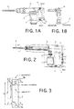
- FIG. 1A / B and FIG. 2 show the essentials in a basic illustration Components of a hand-guided in the context of the invention
- Machine tool M its operating state by means of two acceleration sensors 1a or lb is monitored.
- Fig. 1B is indicated by arrows indicated which acceleration 10 or deflection force in which deflection direction 11 on the machine tool in case of blocking of the tool 8 act.
- the signals from the acceleration sensors 1a, 1b arrive an electronic evaluation unit 3, which is a microprocessor, one in discrete Circuit technology implemented microcomputer, a signal processor or the like can be.
- the digitized signals are in this evaluation unit 3 of the acceleration sensors 1a, 1b are first subtracted from one another, such as explained and justified further below. Then the so obtained Result evaluated using a model or rule-based algorithm, which the operating state of the hand machine tool M when the Acceleration sensors 1a, 1b predicts.
- the invention can be also be used advantageously for those applications in which there are no predictive ones Calculation of the expected twist angle of the hand machine tool M takes place, that is to say in the case of those safety devices that do so Assess acceleration signal generated by tool blocking immediately and when a certain level is exceeded, possibly after interference signal filtering, as well as one and / or two integration, directly to trigger the Use drive interrupter device.
- the method according to the invention and the measuring system based thereon have an effect reliable for any rotation axis of the overall system as well as for if necessary, tilted or warped tool axis, as below under 3 is explained.
- the movement measuring device has at least two Acceleration sensors 1a, 1b, whose measurement results according to the invention subtracted from further processing.
- the disturbance Gravitational acceleration for every possible application position of the power tool eliminated.
- the second sensor 1b in a axis 9 including the axis of rotation in normal operation Level lies.
- the axis of rotation can be assumed to be two-dimensional Take any position and always delivers error-corrected signal, as derived from the following mathematical derivation reveals.
- more than two sensors can also be provided be, then by averaging or a plausibility check the reliability of the signal obtained is increased. If two redundant sensor pairs are provided, the intervals for one Security check to be stretched in principle.
- Equation (3) used in equation (1) in conjunction with equation (2) yields:
- Equation (3 ') inserted in equation (1') in conjunction with equation (2 ') gives:
- any measuring system is suitable within the scope of the invention
- Acceleration sensors or accelerometers i.e. those that are based on piezoelectric, piezoresistive or inertial and / or integrated as Part of a microelectronic circuit are realized.
- the electronic Evaluation unit can either be implemented analogously with the help of Operational amplifiers and corresponding filter circuits or digital using a microprocessor with associated processor interfaces (see DE 43 44 817 C2). It is also possible to use the evaluation unit to realize as fuzzy logic, which is detailed in DE 196 41 618 A1 is described.
- any known measurement method for acceleration, angular velocity or Angle of rotation applicable is mainly from Cost reasons based on linear acceleration sensors, for example referred to piezoelectric measurement methods.
- linear acceleration sensors for example referred to piezoelectric measurement methods.
Landscapes
- Engineering & Computer Science (AREA)
- Mechanical Engineering (AREA)
- Percussive Tools And Related Accessories (AREA)
- Length Measuring Devices With Unspecified Measuring Means (AREA)
- Drilling And Boring (AREA)
- Portable Power Tools In General (AREA)
- Manipulator (AREA)
- Numerical Control (AREA)
Abstract
Description
- Fig. 1A bzw. 1B
- die schematische Darstellung eines Bohrhammers in Seiten- bzw. Rückansicht als Beispiel für eine handgeführte Werkzeugmaschine, die mit zwei Beschleunigungssensoren ausgerüstet ist;
- Fig. 2
- die schematische Teilschnittdarstellung des Bohrhammers nach Fig. 1; und
- Fig. 3
- die Prinzipdarstellung eines Drehbewegungsmodells für eine Handwerkzeugmaschine gemäß Fig. 1, die im dargestellten Beispiel mit zwei Linear-Beschleunigungssensoren ausgerüstet ist.
- a1, a2 =
- Meßsignale des ersten Beschleunigungssensor 1a bzw. des zweiten Beschleunigungssensors 1b; insbesondere repräsentieren a1 und a2 lineare Tangentialbeschleunigungen um jeweilige Drehachsen, die nachfolgend als "Fall 1" bzw. als "Fall 2" einer näheren Betrachtung unterzogen werden.
- d =
- Abstand der Beschleunigungssensoren 1a, 1b;
- r1a1, r1b1 =
- Abstände der Beschleunigungssensoren 1a, 1b für den "Fall 1", bei dem die (gedachte) Drehachse des Werkzeugs, beispielsweise im Fall des Werkzeugblockierens gegenüber der Antriebsachse bzw. Drehachse im Normalbetrieb nach unten versetzt ist; und
- r1a2, r1b2 =
- Abstände der Beschleunigungssensoren 1a, 1b von einer (gedachten) Drehachse für den "Fall 2", d.h., wenn die Drehachse des Werkzeugs im Falle des Blockierens gegenüber der Antriebsachse bzw. Drehachse im Normalbetrieb nach oben versetzt ist;
- ϕ =
- zu erwartender Drehwinkel im Falle des Werkzeugblockierens.



Claims (7)
- Verfahren zur Vermeidung von Unfällen durch Werkzeugblockieren beim Arbeiten mit einer handgeführten Werkzeugmaschine mit rotierendem Werkzeug (8), insbesondere für Bohrhämmer, die mit einer Unterbrechereinrichtung (5, 6) zum Unterbrechen der Wirkung des Antriebsmotors (7) auf das Werkzeug (8) in Abhängigkeit von dem durch eine Bewegungsmeßeinrichtung (1) erfaßten Betriebszustand ausgerüstet ist, dadurch gekennzeichnet, daß die Bewegung der Werkzeugmaschine im Raum an mindestens zwei räumlich voneinander und gegen die Werkzeugachse beabstandeten Stellen der Werkzeugmaschine gemessen wird, und daß die erhaltenen Meßwerte (a1, a2) vor der Berechnung eines die Unterbrechereinrichtung (5, 6) auslösenden Signals voneinander subtrahiert werden.
- Verfahren nach Anspruch 1, dadurch gekennzeichnet, daß die Bewegung der Werkzeugmaschine im Raum an gegen die Werkzeugachse unterschiedlich beabstandeten Stellen gemessen wird.
- Verfahren nach Anspruch 1 oder 2, dadurch gekennzeichnet, daß als Bewegungsgröße die Beschleunigung der Werkzeugmaschine im Raum an mindestens zwei räumlich voneinander beabstandeten Stellen erfaßt wird.
- Verfahren nach Anspruch 3, dadurch gekennzeichnet, daß nach der Subtraktion der von mindestens zwei Beschleunigungssensoren gelieferten Meßwerte unter Vorgabe einer Zeitkonstante aus der durch die Subtraktion erhaltenen Drehbeschleunigungsgröße ein zu erwartender Verdrehwinkel (ϕ) der Werkzeugmaschine (M) vorausschauend berechnet und die Unterbrechereinrichtung (5, 6) aktiviert wird, sobald der berechnete, zu erwartende Verdrehwinkel einen vogebbaren maximal zulässigen Verdrehwinkel überschreitet.
- Einrichtung zur Vermeidung von Unfällen aufgrund von Werkzeugblockierens bei einer handgeführten Werkzeugmaschine mit rotierendem Werkzeug, insbesondere Bohrhämmern, die mit einer Unterbrechereinrichtung (5, 6) zum Unterbrechen der Wirkung des Antriebsmotors (7) auf das Werkzeug (8) in Abhängigkeit von dem durch eine Beschleunigungsmeßeinrichtung (1) erfaßten Betriebszustand ausgerüstet ist, dadurch gekennzeichnet, daß die Beschleunigungsmeßeinrichtung mindestens zwei innerhalb des Gehäuses der Werkzeugmaschine an räumlich voneinander und gegenüber der Werkzeugachse beabstandeten Stellen montierten Beschleunigungssensoren (1a, 1b) ausgerüstet ist, und daß die die Beschleunigungssignale (a1, a2) der Beschleunigungssensoren verarbeitende elektronische Auswerteeinheit (3) eine Subtraktionsstufe enthält, in der die von den Beschleunigungssensoren jeweils gelieferten Signale vor der Errechnung eines Auslösesignals für die Unterbrechereinrichtung (5, 6) voneinander subtrahiert werden.
- Einrichtung nach Anspruch 5, dadurch gekennzeichnet, daß die Beschleunigungssensoren (1a, 1b) Linear-Beschleunigungssensoren sind.
- Einrichtung nach Anspruch 5, dadurch gekennzeichnet, daß mindestens einer der Beschleunigungssensoren (1a, 1b) so angeordnet ist, daß er in normaler Betriebsstellung der Werkzeugmaschine ein maximales Ausgangssignal liefert.
Applications Claiming Priority (2)
| Application Number | Priority Date | Filing Date | Title |
|---|---|---|---|
| DE19857061 | 1998-12-10 | ||
| DE19857061A DE19857061C2 (de) | 1998-12-10 | 1998-12-10 | Verfahren und Einrichtung zur Vermeidung von Unfällen bei handgeführten Werkzeugmaschinen durch Werkzeugblockieren |
Publications (3)
| Publication Number | Publication Date |
|---|---|
| EP1008422A2 true EP1008422A2 (de) | 2000-06-14 |
| EP1008422A3 EP1008422A3 (de) | 2001-09-19 |
| EP1008422B1 EP1008422B1 (de) | 2007-02-14 |
Family
ID=7890654
Family Applications (1)
| Application Number | Title | Priority Date | Filing Date |
|---|---|---|---|
| EP99811119A Expired - Lifetime EP1008422B1 (de) | 1998-12-10 | 1999-12-06 | Verfahren und Einrichtung zur Vermeidung von Unfällen bei handgeführten Werkzeugmaschinen durch Werkzeugblockieren |
Country Status (5)
| Country | Link |
|---|---|
| US (1) | US6111515A (de) |
| EP (1) | EP1008422B1 (de) |
| JP (1) | JP4486728B2 (de) |
| CN (1) | CN1160526C (de) |
| DE (2) | DE19857061C2 (de) |
Cited By (12)
| Publication number | Priority date | Publication date | Assignee | Title |
|---|---|---|---|---|
| EP1227561A2 (de) | 2001-01-24 | 2002-07-31 | HILTI Aktiengesellschaft | Drehendes Elektrohandwerkzeug und Startsicherheitsroutine |
| DE10309414A1 (de) * | 2003-03-05 | 2004-09-23 | Robert Bosch Gmbh | Sensoreinrichtung und zugehöriges Verfahren |
| EP2581168A1 (de) * | 2011-10-13 | 2013-04-17 | Oy Kwh Mirka Ab | Tragbare Maschine |
| EP1714723A3 (de) * | 2005-04-19 | 2014-03-19 | Black & Decker, Inc. | Elektronische Kupplung für Werkzeugspannfutter mit Nebenantrieb und Spindelverriegelung |
| USD703017S1 (en) | 2011-01-07 | 2014-04-22 | Black & Decker Inc. | Screwdriver |
| US9199362B2 (en) | 2010-01-07 | 2015-12-01 | Black & Decker Inc. | Power tool having rotary input control |
| EP2656977A3 (de) * | 2012-04-26 | 2015-12-23 | Robert Bosch Gmbh | Elektrowerkzeug und Verfahren zu seinem Betrieb |
| US9266178B2 (en) | 2010-01-07 | 2016-02-23 | Black & Decker Inc. | Power tool having rotary input control |
| US9475180B2 (en) | 2010-01-07 | 2016-10-25 | Black & Decker Inc. | Power tool having rotary input control |
| EP2288463B1 (de) * | 2008-05-14 | 2016-11-30 | Robert Bosch GmbH | Verfahren zum betrieb einer stichsäge. |
| EP3610990A1 (de) | 2018-08-14 | 2020-02-19 | Hilti Aktiengesellschaft | Steuerungsverfahren für eine handwerkzeugmaschine, handwerkzeugmaschine und system mit der handwerkzeugmaschine und einem ständer |
| US10589413B2 (en) | 2016-06-20 | 2020-03-17 | Black & Decker Inc. | Power tool with anti-kickback control system |
Families Citing this family (54)
| Publication number | Priority date | Publication date | Assignee | Title |
|---|---|---|---|---|
| DE19900882A1 (de) * | 1999-01-12 | 2000-07-13 | Bosch Gmbh Robert | Handwerkzeugmaschine |
| DE10051775A1 (de) * | 2000-10-19 | 2002-05-16 | Hilti Ag | Sicherheitsschaltung für drehendes Elektrohandwerkzeuggerät |
| SE520435C2 (sv) * | 2001-03-30 | 2003-07-08 | Scania Cv Ab | Sätt och anordning för att bestämma cylindertryck vid en förbränningsmotor |
| DE10117121A1 (de) * | 2001-04-06 | 2002-10-17 | Bosch Gmbh Robert | Handwerkzeugmaschine |
| EP2390062B1 (de) * | 2002-09-13 | 2017-03-08 | Black & Decker Inc. | Drehwerkzeug |
| US7015409B2 (en) * | 2002-12-23 | 2006-03-21 | Milwaukee Electric Tool Corporation | Power tool trigger |
| DE10303006B4 (de) * | 2003-01-27 | 2019-01-03 | Hilti Aktiengesellschaft | Handgeführtes Arbeitsgerät |
| DE10309012B3 (de) * | 2003-03-01 | 2004-08-12 | Hilti Ag | Steuerverfahren einer axial schlagenden und drehenden Elektrohandwerkzeugmaschine |
| DE10316844A1 (de) * | 2003-04-11 | 2004-11-04 | Hilti Ag | Steuerung einer Elektrohandwerkzeugmaschine |
| US7395871B2 (en) * | 2003-04-24 | 2008-07-08 | Black & Decker Inc. | Method for detecting a bit jam condition using a freely rotatable inertial mass |
| DE10318798B4 (de) * | 2003-04-25 | 2006-01-26 | Robert Bosch Gmbh | Bohrgerät |
| DE10341974A1 (de) * | 2003-09-11 | 2005-04-21 | Bosch Gmbh Robert | Abschaltschrauber |
| DE102004003202B4 (de) | 2004-01-22 | 2022-05-25 | Robert Bosch Gmbh | Handgriff mit Erfassungseinrichtung |
| US7410006B2 (en) * | 2004-10-20 | 2008-08-12 | Black & Decker Inc. | Power tool anti-kickback system with rotational rate sensor |
| US7552781B2 (en) | 2004-10-20 | 2009-06-30 | Black & Decker Inc. | Power tool anti-kickback system with rotational rate sensor |
| US20060157262A1 (en) * | 2005-01-14 | 2006-07-20 | Jui-Yu Chen | Power tool having presetable digital control of torque output |
| US7650699B2 (en) * | 2005-07-22 | 2010-01-26 | Kazuhiro Yamamoto | Electric drill |
| DK1971262T3 (da) * | 2005-12-23 | 2013-05-27 | Reactec Ltd | Overvågningsapparat til overvågning af et håndholdt værktøj |
| US8316958B2 (en) * | 2006-07-13 | 2012-11-27 | Black & Decker Inc. | Control scheme for detecting and preventing torque conditions in a power tool |
| US20080021590A1 (en) * | 2006-07-21 | 2008-01-24 | Vanko John C | Adaptive control scheme for detecting and preventing torque conditions in a power tool |
| US20090065225A1 (en) * | 2007-09-07 | 2009-03-12 | Black & Decker Inc. | Switchable anti-lock control |
| FR2935496B1 (fr) * | 2008-08-29 | 2014-05-16 | Pellenc Sa | Procede permettant l'arret des outils portatifs lors de mouvements brusques imprevus, et outils portatifs en faisant application |
| JP5537055B2 (ja) * | 2009-03-24 | 2014-07-02 | 株式会社マキタ | 電動工具 |
| JP5448569B2 (ja) * | 2009-05-21 | 2014-03-19 | 株式会社やまびこ | 安全装置付き刈払機 |
| JP5448568B2 (ja) * | 2009-05-21 | 2014-03-19 | 株式会社やまびこ | 安全装置付き作業機 |
| DE102009046789A1 (de) * | 2009-11-17 | 2011-05-19 | Robert Bosch Gmbh | Handwerkzeugmaschinenvorrichtung |
| JP5412249B2 (ja) * | 2009-11-19 | 2014-02-12 | 株式会社マキタ | 手持ち工具 |
| CN102753782B (zh) * | 2010-01-07 | 2015-09-30 | 布莱克和戴克公司 | 具有旋转输入控制的电动螺丝起子 |
| DE102010043032A1 (de) * | 2010-10-28 | 2012-05-03 | Hilti Aktiengesellschaft | Steuerungsverfahren für eine Werkzeugmaschine und eine Werkzeugmaschine |
| US9352456B2 (en) | 2011-10-26 | 2016-05-31 | Black & Decker Inc. | Power tool with force sensing electronic clutch |
| DE102012208913A1 (de) * | 2012-05-25 | 2013-11-28 | Robert Bosch Gmbh | Schlagwerkeinheit |
| DE102012208855A1 (de) * | 2012-05-25 | 2013-11-28 | Robert Bosch Gmbh | Handwerkzeugmaschine |
| GB201212958D0 (en) * | 2012-07-20 | 2012-09-05 | Hosking Peter J | Power tools |
| DE102014202585A1 (de) * | 2013-04-29 | 2014-10-30 | Robert Bosch Gmbh | Handwerkzeugbedieneinheit |
| DE102013212626B4 (de) * | 2013-06-28 | 2024-08-08 | Robert Bosch Gmbh | Handwerkzeugmaschinenvorrichtung |
| DE102014207434A1 (de) * | 2014-04-17 | 2015-10-22 | Robert Bosch Gmbh | Verfahren zum Betreiben einer Handwerkzeugmaschine, Handwerkzeugmaschine |
| CN105082261A (zh) * | 2014-05-13 | 2015-11-25 | 苏州宝时得电动工具有限公司 | 链锯及其控制方法 |
| EP3023200A1 (de) * | 2014-11-20 | 2016-05-25 | HILTI Aktiengesellschaft | Steuerungsverfahren für einen Bohrhammer |
| EP3023202A1 (de) * | 2014-11-20 | 2016-05-25 | HILTI Aktiengesellschaft | Sicherheitsverfahren und Handwerkzeugmaschine |
| EP3023203A1 (de) * | 2014-11-20 | 2016-05-25 | HILTI Aktiengesellschaft | Steuerungsverfahren für eine Handwerkzeugmaschine |
| DE102015205172A1 (de) * | 2015-03-23 | 2016-09-29 | Robert Bosch Gmbh | Werkzeugmaschine, insbesondere Handwerkzeugmaschine, mit einer motorischen Antriebseinheit und mit zumindest einer Sensorvorrichtung |
| JP2017001115A (ja) * | 2015-06-05 | 2017-01-05 | 株式会社マキタ | 作業工具 |
| KR101799432B1 (ko) * | 2015-09-22 | 2017-11-21 | 계양전기 주식회사 | 전동 공구 |
| EP3199303A1 (de) * | 2016-01-29 | 2017-08-02 | HILTI Aktiengesellschaft | Handwerkzeugmaschine |
| JP6757226B2 (ja) * | 2016-10-07 | 2020-09-16 | 株式会社マキタ | 電動工具 |
| SE540015C2 (en) | 2016-10-17 | 2018-02-27 | Husqvarna Ab | Safety arrangement and method for a floor surfacing machine |
| US11529725B2 (en) | 2017-10-20 | 2022-12-20 | Milwaukee Electric Tool Corporation | Power tool including electromagnetic clutch |
| WO2019084280A1 (en) | 2017-10-26 | 2019-05-02 | Milwaukee Electric Tool Corporation | RECLINING CONTROL METHODS FOR ELECTRIC TOOLS |
| CN114174002B (zh) * | 2019-09-20 | 2024-07-09 | 喜利得股份公司 | 用于操作手导式机加工工具的方法和手导式机加工工具 |
| JP7382190B2 (ja) * | 2019-09-26 | 2023-11-16 | 株式会社マキタ | 回転工具 |
| US11691262B2 (en) | 2019-09-26 | 2023-07-04 | Makita Corporation | Electric power tool |
| EP3825066A1 (de) | 2019-11-21 | 2021-05-26 | Hilti Aktiengesellschaft | Verfahren zum betreiben einer handgeführten werkzeugmaschine und handgeführte werkzeugmaschine |
| US11641102B2 (en) | 2020-03-10 | 2023-05-02 | Smart Wires Inc. | Modular FACTS devices with external fault current protection within the same impedance injection module |
| US11845173B2 (en) | 2020-10-16 | 2023-12-19 | Milwaukee Electric Tool Corporation | Anti bind-up control for power tools |
Family Cites Families (17)
| Publication number | Priority date | Publication date | Assignee | Title |
|---|---|---|---|---|
| US4063600A (en) * | 1976-05-05 | 1977-12-20 | Krzes Casey S | Power tool safety mechanism |
| JPS6014487B2 (ja) * | 1980-06-23 | 1985-04-13 | 株式会社明電舎 | 避雷器用素子の接着方法 |
| DE3346215A1 (de) * | 1983-12-21 | 1985-07-11 | Hilti Ag, Schaan | Handwerkzeug mit beweglich gelagerter traegheitsmasse |
| EP0303651B2 (de) * | 1987-03-05 | 1999-12-01 | Robert Bosch Gmbh | Verfahren zum unterbrechen der antriebstätigkeit, insbesondere der schlag- und/oder drehantriebstätigkeit, einer handwerkzeugmaschine |
| DE3707052A1 (de) * | 1987-03-05 | 1988-09-15 | Bosch Gmbh Robert | Verfahren zum unterbrechen der antriebstaetigkeit, insbesondere drehantriebstaetigkeit, einer handwerkzeugmaschine |
| US4866429A (en) * | 1987-08-12 | 1989-09-12 | Scientific Atlanta, Inc. | Automated machine tool monitoring device |
| US5014793A (en) * | 1989-04-10 | 1991-05-14 | Measurement Specialties, Inc. | Variable speed DC motor controller apparatus particularly adapted for control of portable-power tools |
| DE3941756A1 (de) * | 1989-12-18 | 1991-06-20 | Gildemeister Ag | Verfahren zur ermittlung der anwesenheit, der abmessungen oder der richtigen lage und position eines werkstuecks auf einer werkzeugmaschine |
| DE4112012A1 (de) * | 1991-04-12 | 1992-10-15 | Bosch Gmbh Robert | Handwerkzeugmaschine mit blockiersensor |
| US5235472A (en) * | 1991-10-18 | 1993-08-10 | Seagate Technology, Inc. | Apparatus for sensing operating shock on a disk drive |
| DE4334933C2 (de) * | 1993-10-13 | 1997-02-20 | Fraunhofer Ges Forschung | Verfahren und Vorrichtung zum zwangsweisen Abschalten von handgeführten Arbeitsmitteln |
| DE4344817C2 (de) * | 1993-12-28 | 1995-11-16 | Hilti Ag | Verfahren und Einrichtung für handgeführte Werkzeugmaschinen zur Vermeidung von Unfällen durch Werkzeugblockieren |
| DE19628945A1 (de) * | 1995-11-02 | 1997-05-07 | Bosch Gmbh Robert | Verfahren zum Unterbrechen der Antriebstätigkeit einer Handwerkzeugmaschine, sowie nach diesem Verfahren arbeitende Handwerkzeugmaschine |
| EP0771619B2 (de) * | 1995-11-02 | 2004-11-10 | Robert Bosch Gmbh | Verfahren zum Unterbrechen der Antriebstätigkeit einer Handwerkzeugmaschine, sowie nach diesen Verfahren arbeitende Handwerkzeugmaschine |
| DE19641618A1 (de) * | 1996-10-09 | 1998-04-30 | Hilti Ag | Einrichtung und Verfahren für handgeführte Werkzeugmaschinen zur Vermeidung von Unfällen durch Werkzeugblockieren |
| DE19646382A1 (de) * | 1996-11-11 | 1998-05-14 | Hilti Ag | Handgerät |
| DE19646381A1 (de) * | 1996-11-11 | 1998-05-14 | Hilti Ag | Handgerät |
-
1998
- 1998-12-10 DE DE19857061A patent/DE19857061C2/de not_active Expired - Fee Related
-
1999
- 1999-12-01 US US09/452,302 patent/US6111515A/en not_active Expired - Lifetime
- 1999-12-06 DE DE59914191T patent/DE59914191D1/de not_active Expired - Lifetime
- 1999-12-06 EP EP99811119A patent/EP1008422B1/de not_active Expired - Lifetime
- 1999-12-07 CN CNB991228626A patent/CN1160526C/zh not_active Expired - Lifetime
- 1999-12-10 JP JP35144999A patent/JP4486728B2/ja not_active Expired - Lifetime
Cited By (19)
| Publication number | Priority date | Publication date | Assignee | Title |
|---|---|---|---|---|
| EP1227561A2 (de) | 2001-01-24 | 2002-07-31 | HILTI Aktiengesellschaft | Drehendes Elektrohandwerkzeug und Startsicherheitsroutine |
| EP1227561A3 (de) * | 2001-01-24 | 2009-07-22 | HILTI Aktiengesellschaft | Drehendes Elektrohandwerkzeug und Startsicherheitsroutine |
| DE10309414A1 (de) * | 2003-03-05 | 2004-09-23 | Robert Bosch Gmbh | Sensoreinrichtung und zugehöriges Verfahren |
| DE10309414B4 (de) * | 2003-03-05 | 2009-01-08 | Robert Bosch Gmbh | Sensoreinrichtung und zugehöriges Verfahren für eine Handwerkzeugmaschine |
| EP1714723A3 (de) * | 2005-04-19 | 2014-03-19 | Black & Decker, Inc. | Elektronische Kupplung für Werkzeugspannfutter mit Nebenantrieb und Spindelverriegelung |
| EP2288463B1 (de) * | 2008-05-14 | 2016-11-30 | Robert Bosch GmbH | Verfahren zum betrieb einer stichsäge. |
| US9321155B2 (en) | 2010-01-07 | 2016-04-26 | Black & Decker Inc. | Power tool having switch and rotary input control |
| US9199362B2 (en) | 2010-01-07 | 2015-12-01 | Black & Decker Inc. | Power tool having rotary input control |
| US9211636B2 (en) | 2010-01-07 | 2015-12-15 | Black & Decker Inc. | Power tool having rotary input control |
| US9266178B2 (en) | 2010-01-07 | 2016-02-23 | Black & Decker Inc. | Power tool having rotary input control |
| US9321156B2 (en) | 2010-01-07 | 2016-04-26 | Black & Decker Inc. | Power tool having rotary input control |
| US9475180B2 (en) | 2010-01-07 | 2016-10-25 | Black & Decker Inc. | Power tool having rotary input control |
| US10160049B2 (en) | 2010-01-07 | 2018-12-25 | Black & Decker Inc. | Power tool having rotary input control |
| USD703017S1 (en) | 2011-01-07 | 2014-04-22 | Black & Decker Inc. | Screwdriver |
| EP2581168A1 (de) * | 2011-10-13 | 2013-04-17 | Oy Kwh Mirka Ab | Tragbare Maschine |
| EP2656977A3 (de) * | 2012-04-26 | 2015-12-23 | Robert Bosch Gmbh | Elektrowerkzeug und Verfahren zu seinem Betrieb |
| US10589413B2 (en) | 2016-06-20 | 2020-03-17 | Black & Decker Inc. | Power tool with anti-kickback control system |
| US11192232B2 (en) | 2016-06-20 | 2021-12-07 | Black & Decker Inc. | Power tool with anti-kickback control system |
| EP3610990A1 (de) | 2018-08-14 | 2020-02-19 | Hilti Aktiengesellschaft | Steuerungsverfahren für eine handwerkzeugmaschine, handwerkzeugmaschine und system mit der handwerkzeugmaschine und einem ständer |
Also Published As
| Publication number | Publication date |
|---|---|
| JP4486728B2 (ja) | 2010-06-23 |
| DE19857061C2 (de) | 2000-11-02 |
| EP1008422A3 (de) | 2001-09-19 |
| EP1008422B1 (de) | 2007-02-14 |
| JP2000263304A (ja) | 2000-09-26 |
| DE59914191D1 (de) | 2007-03-29 |
| US6111515A (en) | 2000-08-29 |
| CN1160526C (zh) | 2004-08-04 |
| DE19857061A1 (de) | 2000-06-15 |
| CN1256383A (zh) | 2000-06-14 |
Similar Documents
| Publication | Publication Date | Title |
|---|---|---|
| EP1008422B1 (de) | Verfahren und Einrichtung zur Vermeidung von Unfällen bei handgeführten Werkzeugmaschinen durch Werkzeugblockieren | |
| EP0666148B1 (de) | Verfahren und Einrichtung für handgeführte Werkzeugmaschinen zur Vermeidung von Unfällen durch Werkzeugblockieren | |
| EP0580628B1 (de) | Handwerkzeugmaschine mit blockiersensor | |
| EP1157898B1 (de) | Verfahren zur Detektion von Überrollvorgängen bei Kraftfahrzeugen mit Sicherheitseinrichtungen | |
| DE3942011C3 (de) | Einrichtung zur Auslösung einer passiven Sicherheitseinrichtung für Fahrzeuginsassen | |
| EP0980323B1 (de) | Anordnung zum steuern eines insassenschutzmittels eines kraftfahrzeugs | |
| DE10065518B4 (de) | Verfahren zum Auslösen von Rückhaltemitteln in einem Kraftfahrzeug | |
| EP1157899B1 (de) | Verfahren und Sicherheitssystem zur Erkennung eines Überschlages und zur Auslösung einer Sicherheitseinrichtung in einem Kraftfahrzeug | |
| DE4116336C1 (en) | Passive safety device release assembly for motor vehicle occupant - has acceleration pick=ups with sensitivity axes directed to detect angle of frontal impact and supplying evaluating circuit | |
| DE69737104T2 (de) | Sicherheitsvorrichtung für fahrzeuge | |
| DE102016010813B4 (de) | Elektronische Vorrichtung mit Stosserkennungsfunktion | |
| DE19641618A1 (de) | Einrichtung und Verfahren für handgeführte Werkzeugmaschinen zur Vermeidung von Unfällen durch Werkzeugblockieren | |
| EP1445075A2 (de) | Verfahren zum Überwachen einer Maschine, insbesondere eines Roboters, und Maschine mit einer Überwachungseinrichtung | |
| EP1054794A1 (de) | Verfahren und vorrichtung zum auslösen eines rückhaltesystems | |
| EP0771619B2 (de) | Verfahren zum Unterbrechen der Antriebstätigkeit einer Handwerkzeugmaschine, sowie nach diesen Verfahren arbeitende Handwerkzeugmaschine | |
| WO1996039315A1 (de) | Steueranordnung zur auslösung eines rückhaltemittels in einem fahrzeug bei einem seitenaufprall | |
| EP1110064B1 (de) | Verfahren und vorrichtung zum steuern eines insassenschutzmittels eines fahrzeugs | |
| DE19537546A1 (de) | Aufprallerkennungsvorrichtung, insbesondere für ein Sicherheitssystem für Fahrzeuge zur Personenbeförderung | |
| DE10309414B4 (de) | Sensoreinrichtung und zugehöriges Verfahren für eine Handwerkzeugmaschine | |
| DE102004038984A1 (de) | Vorrichtung zur Crashdetektion | |
| DE102008043475B4 (de) | Verfahren zum Steuern einer Einrichtung und Vorrichtung zum Steuern der Einrichtung | |
| EP4031331B1 (de) | Verfahren zum betreiben einer handgeführten werkzeugmaschine und handwerkzeugmaschine | |
| DE10155659A1 (de) | Verfahren zum Bestimmen der für das Auslösen einer passiven Sicherheitseinrichtung in einem Fahrzeug maßgeblichen Crasphasen | |
| EP3610990B1 (de) | Steuerungsverfahren für eine handwerkzeugmaschine, handwerkzeugmaschine und system mit der handwerkzeugmaschine und einem ständer | |
| EP0852193A1 (de) | Verfahren zum Auslösen einer Sicherheitseinrichtung, insbesondere eines Gurtstraffers, in einem Fahrzeug zur Personenbeförderung |
Legal Events
| Date | Code | Title | Description |
|---|---|---|---|
| PUAI | Public reference made under article 153(3) epc to a published international application that has entered the european phase |
Free format text: ORIGINAL CODE: 0009012 |
|
| AK | Designated contracting states |
Kind code of ref document: A2 Designated state(s): AT BE CH CY DE DK ES FI FR GB GR IE IT LI LU MC NL PT SE Kind code of ref document: A2 Designated state(s): CH DE GB LI NL SE |
|
| AX | Request for extension of the european patent |
Free format text: AL;LT;LV;MK;RO;SI |
|
| PUAL | Search report despatched |
Free format text: ORIGINAL CODE: 0009013 |
|
| AK | Designated contracting states |
Kind code of ref document: A3 Designated state(s): AT BE CH CY DE DK ES FI FR GB GR IE IT LI LU MC NL PT SE |
|
| AX | Request for extension of the european patent |
Free format text: AL;LT;LV;MK;RO;SI |
|
| 17P | Request for examination filed |
Effective date: 20020319 |
|
| AKX | Designation fees paid |
Free format text: CH DE GB LI NL SE |
|
| GRAP | Despatch of communication of intention to grant a patent |
Free format text: ORIGINAL CODE: EPIDOSNIGR1 |
|
| GRAS | Grant fee paid |
Free format text: ORIGINAL CODE: EPIDOSNIGR3 |
|
| GRAA | (expected) grant |
Free format text: ORIGINAL CODE: 0009210 |
|
| AK | Designated contracting states |
Kind code of ref document: B1 Designated state(s): CH DE GB LI NL SE |
|
| REG | Reference to a national code |
Ref country code: GB Ref legal event code: FG4D Free format text: NOT ENGLISH |
|
| REG | Reference to a national code |
Ref country code: CH Ref legal event code: EP |
|
| REF | Corresponds to: |
Ref document number: 59914191 Country of ref document: DE Date of ref document: 20070329 Kind code of ref document: P |
|
| GBT | Gb: translation of ep patent filed (gb section 77(6)(a)/1977) |
Effective date: 20070321 |
|
| REG | Reference to a national code |
Ref country code: SE Ref legal event code: TRGR |
|
| PLBE | No opposition filed within time limit |
Free format text: ORIGINAL CODE: 0009261 |
|
| STAA | Information on the status of an ep patent application or granted ep patent |
Free format text: STATUS: NO OPPOSITION FILED WITHIN TIME LIMIT |
|
| 26N | No opposition filed |
Effective date: 20071115 |
|
| PGFP | Annual fee paid to national office [announced via postgrant information from national office to epo] |
Ref country code: SE Payment date: 20181219 Year of fee payment: 20 Ref country code: DE Payment date: 20181210 Year of fee payment: 20 Ref country code: NL Payment date: 20181219 Year of fee payment: 20 |
|
| PGFP | Annual fee paid to national office [announced via postgrant information from national office to epo] |
Ref country code: GB Payment date: 20181218 Year of fee payment: 20 Ref country code: CH Payment date: 20181218 Year of fee payment: 20 |
|
| REG | Reference to a national code |
Ref country code: DE Ref legal event code: R071 Ref document number: 59914191 Country of ref document: DE |
|
| REG | Reference to a national code |
Ref country code: NL Ref legal event code: MK Effective date: 20191205 |
|
| REG | Reference to a national code |
Ref country code: CH Ref legal event code: PL |
|
| REG | Reference to a national code |
Ref country code: GB Ref legal event code: PE20 Expiry date: 20191205 |
|
| REG | Reference to a national code |
Ref country code: SE Ref legal event code: EUG |
|
| PG25 | Lapsed in a contracting state [announced via postgrant information from national office to epo] |
Ref country code: GB Free format text: LAPSE BECAUSE OF EXPIRATION OF PROTECTION Effective date: 20191205 |