EP1008448A1 - Dispositif pour contrôler la température d'une machine à imprimer - Google Patents
Dispositif pour contrôler la température d'une machine à imprimer Download PDFInfo
- Publication number
- EP1008448A1 EP1008448A1 EP99120734A EP99120734A EP1008448A1 EP 1008448 A1 EP1008448 A1 EP 1008448A1 EP 99120734 A EP99120734 A EP 99120734A EP 99120734 A EP99120734 A EP 99120734A EP 1008448 A1 EP1008448 A1 EP 1008448A1
- Authority
- EP
- European Patent Office
- Prior art keywords
- fluid
- temperature control
- temperature
- circuit
- consumer
- Prior art date
- Legal status (The legal status is an assumption and is not a legal conclusion. Google has not performed a legal analysis and makes no representation as to the accuracy of the status listed.)
- Granted
Links
- 238000007639 printing Methods 0.000 title claims description 13
- 239000012530 fluid Substances 0.000 claims abstract description 69
- 238000005496 tempering Methods 0.000 claims abstract description 17
- 238000011144 upstream manufacturing Methods 0.000 claims abstract 2
- 239000003507 refrigerant Substances 0.000 claims description 5
- 239000007788 liquid Substances 0.000 description 4
- 238000001816 cooling Methods 0.000 description 2
- 230000001419 dependent effect Effects 0.000 description 1
- 238000010438 heat treatment Methods 0.000 description 1
- 238000000034 method Methods 0.000 description 1
- 238000007645 offset printing Methods 0.000 description 1
- XLYOFNOQVPJJNP-UHFFFAOYSA-N water Substances O XLYOFNOQVPJJNP-UHFFFAOYSA-N 0.000 description 1
Images
Classifications
-
- B—PERFORMING OPERATIONS; TRANSPORTING
- B41—PRINTING; LINING MACHINES; TYPEWRITERS; STAMPS
- B41F—PRINTING MACHINES OR PRESSES
- B41F7/00—Rotary lithographic machines
- B41F7/20—Details
- B41F7/24—Damping devices
- B41F7/37—Damping devices with supercooling for condensation of air moisture
-
- B—PERFORMING OPERATIONS; TRANSPORTING
- B41—PRINTING; LINING MACHINES; TYPEWRITERS; STAMPS
- B41F—PRINTING MACHINES OR PRESSES
- B41F13/00—Common details of rotary presses or machines
- B41F13/08—Cylinders
- B41F13/22—Means for cooling or heating forme or impression cylinders
-
- B—PERFORMING OPERATIONS; TRANSPORTING
- B41—PRINTING; LINING MACHINES; TYPEWRITERS; STAMPS
- B41F—PRINTING MACHINES OR PRESSES
- B41F31/00—Inking arrangements or devices
- B41F31/002—Heating or cooling of ink or ink rollers
Definitions
- the invention relates to a temperature control device according to a printing press the preamble of claim 1.
- a printing press of this type is known from DE-A-44 29 520.
- an injector is required through which the temperature control device is correspondingly more expensive.
- Further temperature control devices for printing machines are known from DE-A-42 02 544 and DE-A 37 26 820.
- To be tempered Heat consumers or cold consumers are printing press cylinders various types and fountain solution for wet offset printing. The Tempering of the rolls or cylinders can be done by Bath fluid is passed through it or by the Bath fluid is passed through a heat exchanger which air is cooled, which is blown by a fan onto the outer surface of the relevant cylinder or the corresponding roller is blown.
- the object of the invention is to achieve the temperature control device to train a printing press in such a way that it is inexpensive and the Temperature of a consumer can be kept in extremely tight tolerances.
- the invention is used in particular for cooling parts of the printing press, which, without such cooling, would reach temperature values above the temperature value required for an optimal printing process.
- the invention is also suitable for heating Machine parts as long as they are still in a machine start-up phase have not reached their optimal operating temperature.
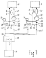
- the temperature control device of a printing press shown in the drawing contains a temperature control fluid circuit 2, which contains a pump 4 and in which a consumer 6 of the printing press can be integrated.
- the consumer 6 can be a cylinder or a roller or a part containing a liquid or be an electronic control circuit or the like within which the temperature within extremely narrow tolerances on a set point or should be kept in a setpoint range, for example a Temperature setpoint, which must not fluctuate more than +/- 0.25 ° C.
- the tempering fluid circuit 2 is tempering fluid through the pump 4 in Direction of an arrow 8 circulates.
- a temperature control fluid source 10 is filled with temperature control fluid and forms one Heat exchanger path, in which a heat exchanger path 12 a Refrigerator 14 is located, through which refrigerant circulates.
- the Refrigerator 14 may be of the type found in refrigerators and Freezers are known and compressed by a gaseous Refrigerant into a liquid refrigerant state and subsequent Expansion in which the refrigerant returns from the liquid state to the gaseous state passes, cold produces.
- a fluid supply line 16 connects the temperature control fluid source 10 to a Inlet 18 in the temperature control fluid circuit 2 at one between the consumer 6 and the suction side 20 of the pump 4 located first connection point.
- a fluid return line 22 connects an outlet 24 of the Tempering fluid circuit 2 at a second connection point between the Suction side 20 of the pump 4 and the consumer 6 with an inlet 26 Thermal fluid source 10.
- controllable valve 28 preferably in Form of an electromagnetic proportional valve, which is arranged in Dependence on the actual temperature value of a temperature sensor 30 more or is opened or closed less widely.
- the temperature sensor 30 is in the bath liquid circuit 2 between the Inlet 18 at the first connection point and the suction side 20 of the pump 4 arranged. It could also be in another place of the Bath fluid circuit can be arranged, however, have tests shown that at this point shown in the drawing faster and more precise temperature controls are possible.
- a flow resistance 32 e.g. in the form of a flow orifice, is in the Bath fluid circuit 2 between the inlet 18 of the first Junction and the outlet 24 of the second junction for generation of a dynamic pressure on its side facing the consumer 6 arranged.
- An electronic control circuit 34 is functional with the temperature sensor 30 and the valve 28 connected and controls the valve 28 and thus his Fluid passage depending on that measured by the temperature sensor 30 Actual temperature value in order to maintain a temperature setpoint in the consumer preferably with the very narrow tolerance of +/- 0.25 ° C.
- the temperature control fluid circuit 2 is a closed circuit. Also the Tempering fluid source 10 together with the fluid supply line 16 forms the Fluid return line 22 and the distance between them Temperature control fluid circuit 2, which contains the flow resistance 30, a closed cycle.
- the temperature fluid circuit 2 is on its between the pressure side 38 of the Pump 4 and the consumer 6 section with a heater 40 Mistake.
- the heater 40 is dependent on the actual temperature of the Temperature sensor 30 and the temperature setpoint of the consumer 6 from the Control circuit 34 can be activated. This allows the consumer 6 in the Start-up phase of the printing press if its temperature is still below its optimum operating temperature, i.e. below its temperature setpoint, are heated by the temperature control fluid of the temperature control fluid circuit 2. Before then the consumer 6 reaches its temperature setpoint, or at the latest when it reaches it, the heater 40 is turned off. If the Temperature setpoint, the valve 28 is activated instead of the heater 40 the tempering fluid circuit 2 via the inlet 18 cooled tempering fluid from the Supply tempering fluid source 10. This feed is because it is a closed system acts, at the same time via the valve 28 corresponding amount of tempering fluid from the tempering fluid circuit 2 Tempering fluid source 10 removed.
- the temperature control fluid is preferred Water.
- Fluid supply lines 16 and fluid return lines 22 connected in parallel are trained differently or preferably the same for others Temperature control devices.
- the same parts are always the same Provide reference numbers and are not described again.
Landscapes
- Engineering & Computer Science (AREA)
- Mechanical Engineering (AREA)
- Inking, Control Or Cleaning Of Printing Machines (AREA)
- Ink Jet (AREA)
Applications Claiming Priority (2)
| Application Number | Priority Date | Filing Date | Title |
|---|---|---|---|
| DE19857107 | 1998-12-10 | ||
| DE19857107A DE19857107A1 (de) | 1998-12-10 | 1998-12-10 | Temperiervorrichtung für Druckmaschinen |
Publications (2)
| Publication Number | Publication Date |
|---|---|
| EP1008448A1 true EP1008448A1 (fr) | 2000-06-14 |
| EP1008448B1 EP1008448B1 (fr) | 2003-01-08 |
Family
ID=7890684
Family Applications (1)
| Application Number | Title | Priority Date | Filing Date |
|---|---|---|---|
| EP99120734A Expired - Lifetime EP1008448B1 (fr) | 1998-12-10 | 1999-10-20 | Dispositif pour contrôler la température d'une machine à imprimer |
Country Status (5)
| Country | Link |
|---|---|
| US (1) | US6289984B1 (fr) |
| EP (1) | EP1008448B1 (fr) |
| JP (1) | JP3117689B2 (fr) |
| CN (1) | CN1257005A (fr) |
| DE (2) | DE19857107A1 (fr) |
Cited By (2)
| Publication number | Priority date | Publication date | Assignee | Title |
|---|---|---|---|---|
| WO2010029023A1 (fr) | 2008-09-15 | 2010-03-18 | Koenig & Bauer Aktiengesellschaft | Unité d’impression et dispositifs et procédés de régulation de la température d’une unité d’impression |
| WO2010105711A3 (fr) * | 2009-03-17 | 2010-11-25 | Koenig & Bauer Aktiengesellschaft | Machines d'impression avec une ou plusieurs unités d'impression prenant la forme de tours d'impression, pour l'impression en couleurs recto-verso, ainsi que dispositifs destinés à tempérer des pièces d'une ou plusieurs des unités d'impression |
Families Citing this family (10)
| Publication number | Priority date | Publication date | Assignee | Title |
|---|---|---|---|---|
| JPH0672888U (ja) * | 1993-03-29 | 1994-10-11 | 鐘紡株式会社 | 衣料収納用充填具 |
| DE10137166A1 (de) | 2000-08-23 | 2002-03-07 | Heidelberger Druckmasch Ag | Verfahren zur Temperierung von Druckformoberflächen während des Druckes |
| DE10328234B4 (de) * | 2002-12-17 | 2005-09-15 | Koenig & Bauer Ag | Verfahren zur Temperierung sowie Vorrichtung zur Temperierung |
| DE102007003619B4 (de) * | 2006-01-19 | 2010-09-16 | Manroland Ag | Druckmaschine |
| DE102008059869B4 (de) * | 2008-12-01 | 2011-02-03 | Technotrans Ag | Druckmaschinentemperiersystem |
| CN102416759B (zh) * | 2011-08-31 | 2014-08-20 | 中国印钞造币总公司 | 一种润版液集中配供循环冷却装置 |
| DE102012206844B4 (de) * | 2012-04-25 | 2015-03-12 | Koenig & Bauer Aktiengesellschaft | Satz von Modulen zur Bildung eines Temperiersystems, Temperiersystem zur Temperierung von Funktionsteilen einer Maschine, Druckanlage mit einer Druckmaschine und einem Temperiersystem sowie Verfahren zur Errichtung eines Temperiersystems in einer Druckanlage |
| DE102015202183A1 (de) * | 2015-02-06 | 2016-08-11 | Koenig & Bauer Ag | Temperieraggregat zur Temperierung von Funktionsteilen einer Druckmaschine sowie Druckanlage mit einer Druckmaschine und einem Temperieraggregat |
| US11110500B2 (en) | 2016-11-28 | 2021-09-07 | Tzu-Chi LIN | Uniform temperature roller system having uniform heat exchange by supercritical fluid |
| TWI640554B (zh) * | 2016-11-28 | 2018-11-11 | 林紫綺 | 均溫擠壓成型系統及其均溫滾輪結構 |
Citations (5)
| Publication number | Priority date | Publication date | Assignee | Title |
|---|---|---|---|---|
| DE2055584A1 (de) * | 1970-11-12 | 1972-05-25 | Windmöller & Hölscher, 4540 Lengerich | Einrichtung zum Konstanthalten der Temperatur der Gegendruckzylinder von Mehrfarbendruckmaschinen |
| DE2250877A1 (de) * | 1972-01-05 | 1973-07-12 | Tools Ltd Nv | Einrichtung zur regelung der betriebstemperatur einer druckereiwalze |
| DE2360611A1 (de) * | 1973-12-05 | 1975-06-19 | Grapho Metronic Gmbh & Co | Farbwerk fuer druckmaschinen |
| EP0383295A2 (fr) * | 1989-02-17 | 1990-08-22 | Heidelberger Druckmaschinen Aktiengesellschaft | Dispositif pour contrôler la température pour machines d'impression |
| DE4429520A1 (de) * | 1994-08-19 | 1996-02-22 | Baldwin Gegenheimer Gmbh | Verfahren und Vorrichtung zur Temperierung von Temperierflüssigkeit in Druckmaschinen |
Family Cites Families (11)
| Publication number | Priority date | Publication date | Assignee | Title |
|---|---|---|---|---|
| US2915298A (en) * | 1955-04-22 | 1959-12-01 | Phillips Petroleum Co | Temperature control system |
| US3202208A (en) * | 1962-08-22 | 1965-08-24 | American Hydrotherm Corp | Heat exchange system with automatic pump control |
| US3756312A (en) * | 1970-12-28 | 1973-09-04 | American Hydrotherm Corp | Heat transfer system for a continuous lead extruder |
| GB1391848A (en) * | 1972-04-21 | 1975-04-23 | Churchill Instr Co Ltd | Temperature controlled systems |
| CH655690B (fr) * | 1982-05-19 | 1986-05-15 | ||
| GB2207636B (en) * | 1987-08-04 | 1991-08-14 | Seiichi Kurosawa | Thermoregulator |
| JP2906381B2 (ja) | 1990-08-06 | 1999-06-21 | 株式会社小森コーポレーション | 印刷機の温度制御方法および温度制御装置 |
| JPH04117753A (ja) | 1990-09-06 | 1992-04-17 | Fujitsu Ltd | 着信方路自動案内応答方式 |
| JPH05253790A (ja) * | 1992-03-13 | 1993-10-05 | Toshiba Mach Co Ltd | 工作機械の超精密温度制御システム及びその制御方法 |
| JP3212480B2 (ja) | 1995-04-25 | 2001-09-25 | 三菱重工業株式会社 | 印刷機の温度制御装置 |
| DE29716582U1 (de) * | 1997-09-15 | 1997-11-06 | Technotrans GmbH, 48336 Sassenberg | Temperierungsanordnung bei Druckmaschinen |
-
1998
- 1998-12-10 DE DE19857107A patent/DE19857107A1/de not_active Withdrawn
-
1999
- 1999-10-20 DE DE59903964T patent/DE59903964D1/de not_active Expired - Lifetime
- 1999-10-20 EP EP99120734A patent/EP1008448B1/fr not_active Expired - Lifetime
- 1999-12-03 US US09/454,050 patent/US6289984B1/en not_active Expired - Fee Related
- 1999-12-06 JP JP11346243A patent/JP3117689B2/ja not_active Expired - Fee Related
- 1999-12-09 CN CN99124352A patent/CN1257005A/zh active Pending
Patent Citations (5)
| Publication number | Priority date | Publication date | Assignee | Title |
|---|---|---|---|---|
| DE2055584A1 (de) * | 1970-11-12 | 1972-05-25 | Windmöller & Hölscher, 4540 Lengerich | Einrichtung zum Konstanthalten der Temperatur der Gegendruckzylinder von Mehrfarbendruckmaschinen |
| DE2250877A1 (de) * | 1972-01-05 | 1973-07-12 | Tools Ltd Nv | Einrichtung zur regelung der betriebstemperatur einer druckereiwalze |
| DE2360611A1 (de) * | 1973-12-05 | 1975-06-19 | Grapho Metronic Gmbh & Co | Farbwerk fuer druckmaschinen |
| EP0383295A2 (fr) * | 1989-02-17 | 1990-08-22 | Heidelberger Druckmaschinen Aktiengesellschaft | Dispositif pour contrôler la température pour machines d'impression |
| DE4429520A1 (de) * | 1994-08-19 | 1996-02-22 | Baldwin Gegenheimer Gmbh | Verfahren und Vorrichtung zur Temperierung von Temperierflüssigkeit in Druckmaschinen |
Cited By (4)
| Publication number | Priority date | Publication date | Assignee | Title |
|---|---|---|---|---|
| WO2010029023A1 (fr) | 2008-09-15 | 2010-03-18 | Koenig & Bauer Aktiengesellschaft | Unité d’impression et dispositifs et procédés de régulation de la température d’une unité d’impression |
| WO2010105711A3 (fr) * | 2009-03-17 | 2010-11-25 | Koenig & Bauer Aktiengesellschaft | Machines d'impression avec une ou plusieurs unités d'impression prenant la forme de tours d'impression, pour l'impression en couleurs recto-verso, ainsi que dispositifs destinés à tempérer des pièces d'une ou plusieurs des unités d'impression |
| US8327762B2 (en) | 2009-03-17 | 2012-12-11 | Koenig & Bauer Aktiengsellschaft | Printing presses having one or more printing units embodied as printing towers for double-sided multicolor printing, and devices for controlling the temperature of components of one or more of the printing units |
| EP2639065A1 (fr) * | 2009-03-17 | 2013-09-18 | Koenig & Bauer Aktiengesellschaft | Machine d'impression dotée d'une ou plusieurs unités d'impression configurées sous forme de tours d'impression pour l'impression en couleur recto-verso et dispositif destiné à tempérer des éléments d'une ou plusieurs des unités d'impression |
Also Published As
| Publication number | Publication date |
|---|---|
| DE59903964D1 (de) | 2003-02-13 |
| US6289984B1 (en) | 2001-09-18 |
| JP3117689B2 (ja) | 2000-12-18 |
| CN1257005A (zh) | 2000-06-21 |
| DE19857107A1 (de) | 2000-06-15 |
| JP2000168038A (ja) | 2000-06-20 |
| EP1008448B1 (fr) | 2003-01-08 |
Similar Documents
| Publication | Publication Date | Title |
|---|---|---|
| EP0553447B1 (fr) | Système de refroidissement de plaques d'impression pour une machine à imprimer | |
| EP1016521B1 (fr) | Dispositif de tempérage d'une machine d'impression | |
| DE2823570C2 (de) | Vorrichtung zur Reinigung von Flüssigkeiten, insbesondere in chemischen Prozessen | |
| EP0693372B1 (fr) | Dispositif de contrÔle de la température pour machines d'impression | |
| EP1008448B1 (fr) | Dispositif pour contrôler la température d'une machine à imprimer | |
| DE10123489B4 (de) | Vorrichtung zum Kühlen einer Materialbahn | |
| EP2209631B1 (fr) | Système de thermorégulation pour machines à imprimer, à plusieurs niveaux de température | |
| DE102007003619B4 (de) | Druckmaschine | |
| DE29716582U1 (de) | Temperierungsanordnung bei Druckmaschinen | |
| EP1533116A1 (fr) | Dispositif pour contrôler la température d'une machine à imprimer | |
| EP1114971A2 (fr) | Dispositif de refroidissement | |
| DE4000912C1 (fr) | ||
| DE4429520A1 (de) | Verfahren und Vorrichtung zur Temperierung von Temperierflüssigkeit in Druckmaschinen | |
| EP0693375B1 (fr) | Dispositif de régulation de la température pour une imprimante | |
| DE29608045U1 (de) | Anordnung zur Temperierung eines Feuchtmittels und/oder ausgewählter Walzen einer Druckmaschine | |
| EP1572459B1 (fr) | Procede pour temperer, systeme de regulation et dispositif pour temperer | |
| EP2018964A1 (fr) | Machine d'impression avec dispositif de contrôle de la température | |
| EP2326505B1 (fr) | Unité d impression et dispositifs et procédés de régulation de la température d'une unité d'impression | |
| DE102006048770B4 (de) | Gerät zur Temperierung von Formwerkzeugen, beispielweise von Spritzgießmaschinen | |
| DE3938341C1 (fr) | ||
| DE9218193U1 (de) | Druckmaschinen-Temperierungssystem | |
| DE29520464U1 (de) | Anordnung zur Temperierung eines Feuchtmittels und/oder ausgewählter Walzen einer Druckmaschine | |
| EP1958771B1 (fr) | Dispositif de régulation thermique d'une presse d'impression | |
| DE2805215B1 (de) | Kuehlvorrichtung fuer eine Druckgiess- oder Spritzgiessform | |
| DE2448818A1 (de) | Waermeuebertragungsanlage |
Legal Events
| Date | Code | Title | Description |
|---|---|---|---|
| PUAI | Public reference made under article 153(3) epc to a published international application that has entered the european phase |
Free format text: ORIGINAL CODE: 0009012 |
|
| 17P | Request for examination filed |
Effective date: 20000408 |
|
| AK | Designated contracting states |
Kind code of ref document: A1 Designated state(s): DE FR GB IT SE |
|
| AX | Request for extension of the european patent |
Free format text: AL;LT;LV;MK;RO;SI |
|
| AKX | Designation fees paid |
Free format text: DE FR GB IT SE |
|
| 17Q | First examination report despatched |
Effective date: 20010301 |
|
| GRAG | Despatch of communication of intention to grant |
Free format text: ORIGINAL CODE: EPIDOS AGRA |
|
| GRAG | Despatch of communication of intention to grant |
Free format text: ORIGINAL CODE: EPIDOS AGRA |
|
| GRAH | Despatch of communication of intention to grant a patent |
Free format text: ORIGINAL CODE: EPIDOS IGRA |
|
| RAP1 | Party data changed (applicant data changed or rights of an application transferred) |
Owner name: BALDWIN GERMANY GMBH |
|
| GRAH | Despatch of communication of intention to grant a patent |
Free format text: ORIGINAL CODE: EPIDOS IGRA |
|
| GRAA | (expected) grant |
Free format text: ORIGINAL CODE: 0009210 |
|
| AK | Designated contracting states |
Kind code of ref document: B1 Designated state(s): DE FR GB IT SE |
|
| REG | Reference to a national code |
Ref country code: GB Ref legal event code: FG4D Free format text: NOT ENGLISH |
|
| GBT | Gb: translation of ep patent filed (gb section 77(6)(a)/1977) |
Effective date: 20030108 |
|
| REF | Corresponds to: |
Ref document number: 59903964 Country of ref document: DE Date of ref document: 20030213 Kind code of ref document: P |
|
| ET | Fr: translation filed | ||
| PLBQ | Unpublished change to opponent data |
Free format text: ORIGINAL CODE: EPIDOS OPPO |
|
| PLBI | Opposition filed |
Free format text: ORIGINAL CODE: 0009260 |
|
| PG25 | Lapsed in a contracting state [announced via postgrant information from national office to epo] |
Ref country code: GB Free format text: LAPSE BECAUSE OF NON-PAYMENT OF DUE FEES Effective date: 20031020 |
|
| PG25 | Lapsed in a contracting state [announced via postgrant information from national office to epo] |
Ref country code: SE Free format text: LAPSE BECAUSE OF NON-PAYMENT OF DUE FEES Effective date: 20031021 |
|
| PLAZ | Examination of admissibility of opposition: despatch of communication + time limit |
Free format text: ORIGINAL CODE: EPIDOSNOPE2 |
|
| PLAQ | Examination of admissibility of opposition: information related to despatch of communication + time limit deleted |
Free format text: ORIGINAL CODE: EPIDOSDOPE2 |
|
| PLAX | Notice of opposition and request to file observation + time limit sent |
Free format text: ORIGINAL CODE: EPIDOSNOBS2 |
|
| 26 | Opposition filed |
Opponent name: TECHNOTRANS AG Effective date: 20031008 |
|
| PLBB | Reply of patent proprietor to notice(s) of opposition received |
Free format text: ORIGINAL CODE: EPIDOSNOBS3 |
|
| EUG | Se: european patent has lapsed | ||
| GBPC | Gb: european patent ceased through non-payment of renewal fee |
Effective date: 20031020 |
|
| PG25 | Lapsed in a contracting state [announced via postgrant information from national office to epo] |
Ref country code: FR Free format text: LAPSE BECAUSE OF NON-PAYMENT OF DUE FEES Effective date: 20040630 |
|
| REG | Reference to a national code |
Ref country code: FR Ref legal event code: ST |
|
| PLAQ | Examination of admissibility of opposition: information related to despatch of communication + time limit deleted |
Free format text: ORIGINAL CODE: EPIDOSDOPE2 |
|
| PLAR | Examination of admissibility of opposition: information related to receipt of reply deleted |
Free format text: ORIGINAL CODE: EPIDOSDOPE4 |
|
| PLBD | Termination of opposition procedure: decision despatched |
Free format text: ORIGINAL CODE: EPIDOSNOPC1 |
|
| PLBQ | Unpublished change to opponent data |
Free format text: ORIGINAL CODE: EPIDOS OPPO |
|
| PLAB | Opposition data, opponent's data or that of the opponent's representative modified |
Free format text: ORIGINAL CODE: 0009299OPPO |
|
| PLBP | Opposition withdrawn |
Free format text: ORIGINAL CODE: 0009264 |
|
| PLBM | Termination of opposition procedure: date of legal effect published |
Free format text: ORIGINAL CODE: 0009276 |
|
| STAA | Information on the status of an ep patent application or granted ep patent |
Free format text: STATUS: OPPOSITION PROCEDURE CLOSED |
|
| 27C | Opposition proceedings terminated |
Effective date: 20050225 |
|
| PG25 | Lapsed in a contracting state [announced via postgrant information from national office to epo] |
Ref country code: IT Free format text: LAPSE BECAUSE OF NON-PAYMENT OF DUE FEES Effective date: 20051020 |
|
| PGFP | Annual fee paid to national office [announced via postgrant information from national office to epo] |
Ref country code: DE Payment date: 20121025 Year of fee payment: 14 |
|
| REG | Reference to a national code |
Ref country code: DE Ref legal event code: R119 Ref document number: 59903964 Country of ref document: DE Effective date: 20140501 |
|
| PG25 | Lapsed in a contracting state [announced via postgrant information from national office to epo] |
Ref country code: DE Free format text: LAPSE BECAUSE OF NON-PAYMENT OF DUE FEES Effective date: 20140501 |