EP1008468B1 - Support d'attelage - Google Patents
Support d'attelage Download PDFInfo
- Publication number
- EP1008468B1 EP1008468B1 EP99124240A EP99124240A EP1008468B1 EP 1008468 B1 EP1008468 B1 EP 1008468B1 EP 99124240 A EP99124240 A EP 99124240A EP 99124240 A EP99124240 A EP 99124240A EP 1008468 B1 EP1008468 B1 EP 1008468B1
- Authority
- EP
- European Patent Office
- Prior art keywords
- support according
- coupling support
- cross bar
- holder
- connecting element
- Prior art date
- Legal status (The legal status is an assumption and is not a legal conclusion. Google has not performed a legal analysis and makes no representation as to the accuracy of the status listed.)
- Expired - Lifetime
Links
- 230000008878 coupling Effects 0.000 claims abstract description 40
- 238000010168 coupling process Methods 0.000 claims abstract description 40
- 238000005859 coupling reaction Methods 0.000 claims abstract description 40
- 239000000463 material Substances 0.000 claims description 12
- 229910052751 metal Inorganic materials 0.000 claims description 4
- 239000002184 metal Substances 0.000 claims description 4
- 229910000639 Spring steel Inorganic materials 0.000 claims description 3
- 210000002414 leg Anatomy 0.000 description 17
- 229910052782 aluminium Inorganic materials 0.000 description 5
- XAGFODPZIPBFFR-UHFFFAOYSA-N aluminium Chemical compound [Al] XAGFODPZIPBFFR-UHFFFAOYSA-N 0.000 description 5
- 238000004519 manufacturing process Methods 0.000 description 4
- 230000002349 favourable effect Effects 0.000 description 3
- 229910000831 Steel Inorganic materials 0.000 description 2
- 239000000969 carrier Substances 0.000 description 2
- 125000006850 spacer group Chemical group 0.000 description 2
- 239000010959 steel Substances 0.000 description 2
- 238000010521 absorption reaction Methods 0.000 description 1
- 230000009286 beneficial effect Effects 0.000 description 1
- 230000015572 biosynthetic process Effects 0.000 description 1
- 230000001419 dependent effect Effects 0.000 description 1
- 238000010586 diagram Methods 0.000 description 1
- 230000000694 effects Effects 0.000 description 1
- 238000005516 engineering process Methods 0.000 description 1
- 238000009434 installation Methods 0.000 description 1
- 210000000689 upper leg Anatomy 0.000 description 1
- 238000003466 welding Methods 0.000 description 1
Images

Classifications
-
- B—PERFORMING OPERATIONS; TRANSPORTING
- B60—VEHICLES IN GENERAL
- B60D—VEHICLE CONNECTIONS
- B60D1/00—Traction couplings; Hitches; Draw-gear; Towing devices
- B60D1/48—Traction couplings; Hitches; Draw-gear; Towing devices characterised by the mounting
- B60D1/485—Traction couplings; Hitches; Draw-gear; Towing devices characterised by the mounting mounted by means of transversal members attached to the frame of a vehicle
Definitions
- the invention relates to a coupling support for motor vehicles, in particular for passenger vehicles a substantially along a portion of a rear bumper extending cross member, on which a trailer hitch is mountable, and two longitudinally the cross member spaced apart Holder, which carry the cross member and which with at one Body of the motor vehicle provided mounting sites are connectable (see, for example, US-A-4 032 170).
- Such coupling carriers are known from the prior art known.
- these clutch carriers are usually the Holder rigidly connected to the cross member and form one Unit.
- Such a rigid connection of the holder with the Cross beams usually take place in the context of a joint connection, preferably a welded joint, however when towing all on the towing hitch must take acting load peaks, and, as they usually designed as corner welding connection, therefore with high load stability must be performed.
- the coupling carrier is the respective Body of the motor vehicle adapt and thus is for each body of different types of vehicles specially designed for this type clutch carrier with make a firm joint connection between holder and cross member, so that the rationalization potential is limited.
- the invention is therefore based on the object, a To provide coupling carrier of the generic type, which as easy as possible to produce.
- each Connecting element a in the longitudinal direction of the cross member extending and associated with this first Section and one in the longitudinal direction of the body extending and connected to the respective holder second section.
- each connecting element with its first Section with the cross member in the area of one end the same is connected.
- first portion of the connecting element in a Insert or form the end opening of the cross member that it engages over the cross member end is then possible if each connecting element with its first Section with the cross member in the area of one end the same is connected.
- each connecting element in the longitudinal direction of Body along the respective holder extends, so that also a simple, only on train loaded connection can be realized with the holder.
- the connecting element could be used as corner angle or T-piece be formed to connect to the cross member and to create the respective holder.
- each Connecting element between the cross member and the respective Holder forms an arc section as an intermediate piece.
- arc section has the advantage that it is in simple and at the same time stable way the possibility manages to initiate the forces from the cross member into the holders, without that corner areas arise in which on the Towbar acting load peaks favoring a breakage Tensions occur.
- connection between the connecting elements and the holders have been given no further details. So it would be possible in principle, even between the fasteners and provide the holders with a joint connection.
- a particularly advantageous solution provides that the connecting elements with the holders by positive locking elements are connectable.
- Particularly simple positive locking elements are those which the Holder enforce such form-locking elements, for example Bolts, screws or rivets or be similar.
- connection between the connecting elements and the cross member by positive locking elements.
- Positive locking elements are preferably those which wall areas enforce the cross member.
- Such positive locking elements bolts, screws or Rivets. '
- connection between the connectors and the holder and / or the cross member by means of positive locking elements the great advantage that thereby even in the manufacture of the coupling carrier itself at already existing dimensions of the holder, the fasteners and the cross member adjustments, if necessary different body styles are possible thereby that the positioning of the interlocking elements is variable. For example, it is possible by changing the Location of holes still make adjustments in a simple manner.
- the e.g. inventive elasticity in the connecting elements creates the possibility of acting on the hitch Peak loads on the one hand with regard to their effect on the Stability of the clutch carrier to eliminate and also The load peaks also intercept so that they are not Negatively affect the mounting positions of the body, since due to the elasticity in the area of the connecting elements the load peaks are flattened in their course and thus already weakened on the assembly sites of the body of the motor vehicle act.
- Such a design of the connecting elements can be realize particularly advantageous if this one Have bow portion as an intermediate piece and if the Bow section essentially the elastic behavior of the Determined connecting elements.
- the realization of the elastic behavior by means of the arc portion of the connecting elements is particularly advantageous because the possibility has already been created by the bow only by deformation of the bow itself an elasticity to get in the behavior of the connecting element, without this affects the cross member or the holders.
- the connecting body can then realize when he is along a curved line extends and serves to the arc portion of the connecting element to build.
- the connecting body is as Flat material strut formed.
- the connecting body of resilient steel is formed.
- each connecting body itself with a cross beam side leg extends along the cross member.
- the connecting body engages with the cross beam side leg in one end opening of the respective cross member.
- connection of the connecting body preferably provided with the holder that each connecting body along with a holder side leg the respective holder extends, so that in a simple manner a connection, in particular a positive connection be produced between the holder side leg and the holder is.
- connection element In principle, it would be sufficient to make the connection element to produce such a connecting body. A very high rigidity and stability, nevertheless however, sufficient elasticity can be achieved if each connecting element consists of two connecting bodies is trained.
- the two connecting bodies of a connecting element are arranged so that they are juxtaposed at a distance are arranged and thereby a sufficient great stability, especially in the area of the bow section having the connecting body.
- a particularly favorable solution provides that the respective Holder lies substantially between the connecting bodies and thus in the area of the holder-side legs simultaneously represents a spacer between the connecting bodies, which then preferably starting from the holder in the distance bent from each other to the arcuate portion of the connecting element to build.
- each holder two spaced apart Mounting body comprises, wherein each mounting body for mounting is provided at a mounting point of the body.
- the two mounting bodies could then, if they are each with the holder-side legs of the respective connecting element are connected, be provided separately. To one However, to obtain precise alignment of the mounting body is preferably provided that the mounting body with each other are connected.
- the mounting body through a web with each other are connected.
- the cross member is a square tube trained, which makes it particularly easy to opposite walls of the connecting body in To fix distance from each other, so that at the same time also the cross member as a spacer between the two connecting bodies a connecting element is used.
- the cross member made of light metal, in particular Aluminum manufactured to save weight Contribute coupling carrier.
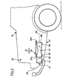
- FIG. 1 to 3 An embodiment of a coupling carrier according to the invention, shown in Fig. 1 to 3, and as a whole with 10th denotes, serves to fix a conventional Trailer coupling 12, comprising a ball neck 14, which a ball head 16 carries on a body 18 of a motor vehicle, in particular a passenger vehicle.
- the Body 18 includes for mounting the coupling carrier on both sides in the rear area 20 and near a body floor 22 provided mounting locations 24, 26, each mounting location, as exemplified by the example of mounting point 26, two mounting points 26a, 26b, which in the longitudinal direction 28 of the body arranged consecutively are.
- a holder 30, 32 preferably made of aluminum, connectable, which then over in each case an inventive connecting element 40, 42 with a cross member 44 is connected, with its longitudinal direction 46 transversely, preferably perpendicular to the longitudinal direction 28th the vehicle body 18 extends, preferably parallel to a rear bumper 48 of the body 18 and is visually obscured by this bumper 48.
- the cross member 44 then carries in turn preferably in a central fastening region 50, the trailer coupling 12, which be formed in various ways can.
- the trailer coupling 12 may be a trailer coupling 12 act with fixedly mounted on the cross member 44 ball neck 14 or a hitch 12 with detachable ball neck 14th or with a pivoting ball neck, each of the Body-fixed part of the hitch 12 at the attachment area 50 is mounted.
- the cross member 44 is preferably made of a square tube, in particular a square tube made of aluminum and each at its ends 52, 54 open, so that in this the corresponding connecting elements 40 and 42 engage can.
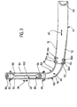
- each of the connecting elements 40 comprises 42 two flat material struts 60, 62, which are spaced apart run and cross-member side legs 64, 66 have, which in the cross member 44 in the region of the open Ends 52, 54 engage and preferably each with Screws 68, 70 with opposite side walls 72 and 74 of the crossbar formed as a square tube 44th are bolted.
- the cross beam side leg 64 the outer sheet bar 60 with the rear side wall 72 of the cross member 44 screwed and the cross member side Leg 66 of the inner flat material strut 62 with the front side wall 74 of the cross member 44th
- the flat material struts 60, 62 comprise arc segments of the connecting bodies 76, 78, which, starting from the substantially transversely to Longitudinal direction 28 of the body extending cross member side Thighs 64, 66 are approximately horizontal curve level 80 so far, until they with holder side Legs 82 and 84 approximately in the longitudinal direction 28 of the body 18 run.
- the respective holders 30 and 32 which two in the Longitudinal direction 28 spaced apart mounting body, namely a rear mounting body 86 and a front mounting body 88, includes.
- Each of the mounting body 86, 88 is located between the two holder-side legs 82 and 84 and is preferably through both the holder side Legs 82 and 84 and the respective mounting body 86 and 88 by cross-threaded 90 and 92nd connected to the holder-side legs 82 and 84, respectively.
- each of the mounting body 86 and 88 with a mounting element 94 or 96 provided, which creates the possibility to connect to the mounting points 26a, 26b.
- the two of the respective holder 30, 32nd enclosed mounting body 86, 88 additionally by a Connecting web 102 connected, which on the one hand for ensures that the two mounting body 86, 88 in particular with the mounting elements 94, 96 in a precisely through the mounting points 26a, b defined distance and in exactly defined Orientation to each other, so that a trouble-free Installation on the body 18 is possible.
Landscapes
- Engineering & Computer Science (AREA)
- Transportation (AREA)
- Mechanical Engineering (AREA)
- Body Structure For Vehicles (AREA)
- Arrangement Of Transmissions (AREA)
- Seal Device For Vehicle (AREA)
- Forklifts And Lifting Vehicles (AREA)
- Connection Of Plates (AREA)
Claims (25)
- Support d'attelage pour véhicules automobiles, en particulier pour des voitures particulières, comprenant une traverse (44) s'étendant essentiellement le long d'une partie d'un pare-chocs (48) arrière, sur laquelle un attelage de remorque (12) peut être monté, et deux supports (30, 32) espacés l'un de l'autre dans le sens longitudinal de la traverse (44), qui supportent la traverse (44) et qui peuvent être reliés en des points de montage (24, 26) prévus sur une carrosserie du véhicule, caractérisé en ce que des éléments de liaison (40, 42) s'étendant entre la traverse (44) et les supports (30, 32) relient de façon élastique la traverse (44) aux supports (30, 32) en ce qui concerne des pointes de charge d'éventuelles agissant sur l'attelage de remorque (12) et en ce que chaque élément de liaison (40, 42) est formé d'au moins un corps de liaison (76, 78) s'étendant le long d'une ligne, résistant à la traction dans le sens de son étirement longitudinal et élastique transversalement à l'étirement longitudinal.
- Support d'attelage selon la revendication 1, caractérisé en ce que chaque élément de liaison (40, 42) présente une première partie (64, 66) s'étendant dans le sens longitudinal (46) de la traverse et reliée à celle-ci et une seconde partie (82, 84) s'étendant à peu près dans le sens longitudinal (28) de la carrosserie et reliée au support (30, 32) respectif.
- Support d'attelage selon la revendication 2, caractérisé en ce que chaque élément de liaison (40, 42) est relié par sa première partie (64, 66) à la traverse (44) dans la zone respectivement d'une extrémité (52, 54) de la traverse.
- Support d'attelage selon la revendication 2 ou 3, caractérisé en ce que chaque élément de liaison s'étend avec sa seconde partie (82, 84) à peu près dans le sens longitudinal (28) de la carrosserie (18) le long du support (30, 32) respectif.
- Support d'attelage selon l'une quelconque des revendications précédentes, caractérisé en ce que chaque élément (40, 42) présente une partie coudée (76, 78) comme pièce intermédiaire entre la traverse (44) et le support (30, 32) respectif.
- Support d'attelage selon l'une quelconque des revendications précédentes, caractérisé en ce que les éléments de liaison (40, 42) peuvent être reliés aux supports (30, 32) par des éléments de fermeture mécanique (90, 92).
- Support d'attelage selon la revendication 6, caractérisé en ce que les éléments de fermeture mécanique (90, 92) traversent le support (30, 32).
- Support d'attelage selon l'une quelconque des revendications précédentes, caractérisé en ce que les éléments de liaison (40, 42) peuvent être reliés à la traverse (44) par des éléments de fermeture mécanique (68, 70).
- Support d'attelage selon la revendication 8, caractérisé en ce que les éléments de fermeture mécanique (68, 70) traversent une paroi (72, 74) de la traverse (44).
- Support d'attelage selon l'une quelconque des revendications précédentes, caractérisé en ce que le corps de liaison (76, 78) s'étend le long d'une ligne incurvée.
- Support d'attelage selon l'une quelconque des revendications précédentes, caractérisé en ce que le corps de liaison (76, 78) est conçu comme un montant à matériau plat.
- Support d'attelage selon l'une quelconque des revendications précédentes, caractérisé en ce que le corps de liaison (76, 78) est formé d'acier élastique comme un ressort.
- Support d'attelage selon l'une quelconque des revendications précédentes, caractérisé en ce qu'une partie du coude de l'élément de liaison (40, 42) détermine pour l'essentiel le comportement élastique de l'élément de liaison (40, 42) concerné.
- Support d'attelage selon l'une quelconque des revendications précédentes, caractérisé en ce que chaque corps de liaison (76, 78) s'étend avec une branche (64, 66) côté traverse le long de la traverse (44).
- Support d'attelage selon l'une quelconque des revendications précédentes, caractérisé en ce que chaque corps de liaison (76, 78) s'étend avec une branche (82, 84) côté support le long du support (30, 32) respectif.
- Support d'attelage selon l'une quelconque des revendications précédentes, caractérisé en ce que chaque élément de liaison (40, 48) est formé de deux corps de liaison (76, 78).
- Support d'attelage selon la revendication 16, caractérisé en ce que les deux corps de liaison (76, 78) d'un élément de liaison (40, 42) sont disposés à distance l'un à côté de l'autre.
- Support d'attelage selon la revendication 16 ou 17, caractérisé en ce que le support (30, 32) respectif s'engage entre les deux corps de liaison (76, 78).
- Support d'attelage selon la revendication (18), caractérisé en ce que le support (30, 32) respectif est disposé sensiblement entre les corps de liaison (76, 78).
- Support d'attelage selon l'une quelconque des revendications précédentes, caractérisé en ce que chaque support (30, 32) comprend deux corps de montage disposés à distance l'un de l'autre.
- Support d'attelage selon la revendication 20, caractérisé en ce que les corps de montage (86, 88) sont reliés entre eux.
- Support d'attelage selon la revendication 21, caractérisé en ce que les corps de montage (86, 88) sont reliés entre eux par une barrette (102).
- Support d'attelage selon l'une quelconque des revendications précédentes, caractérisé en ce que la traverse (44) est conçue comme un tube.
- Support d'attelage selon l'une quelconque des revendications précédentes, caractérisé en ce que la traverse est fabriquée en métal léger.
- Support d'attelage selon l'une quelconque des revendications précédentes, caractérisé en ce que les supports (30, 32) sont fabriqués en métal léger.
Applications Claiming Priority (2)
| Application Number | Priority Date | Filing Date | Title |
|---|---|---|---|
| DE19857321A DE19857321A1 (de) | 1998-12-11 | 1998-12-11 | Kupplungsträger |
| DE19857321 | 1998-12-11 |
Publications (4)
| Publication Number | Publication Date |
|---|---|
| EP1008468A2 EP1008468A2 (fr) | 2000-06-14 |
| EP1008468A3 EP1008468A3 (fr) | 2000-08-23 |
| EP1008468B1 true EP1008468B1 (fr) | 2004-03-03 |
| EP1008468B2 EP1008468B2 (fr) | 2009-08-05 |
Family
ID=7890824
Family Applications (1)
| Application Number | Title | Priority Date | Filing Date |
|---|---|---|---|
| EP99124240A Expired - Lifetime EP1008468B2 (fr) | 1998-12-11 | 1999-12-04 | Support d'attelage |
Country Status (3)
| Country | Link |
|---|---|
| EP (1) | EP1008468B2 (fr) |
| AT (1) | ATE260780T1 (fr) |
| DE (2) | DE19857321A1 (fr) |
Families Citing this family (12)
| Publication number | Priority date | Publication date | Assignee | Title |
|---|---|---|---|---|
| DE10061491C1 (de) * | 2000-12-09 | 2002-04-18 | Porsche Ag | Anhängezugvorrichtung |
| DE10315690B4 (de) * | 2003-04-07 | 2013-07-25 | Audi Ag | Befestigungsvorrichtung für eine Anhängevorrichtung an einem Längsträger eines Kraftfahrzeuges |
| NL1030120C2 (nl) * | 2005-10-05 | 2007-04-06 | Egbert Berend Holtkamp | Aanhangwagen die achter een personenauto gekoppeld kan worden, werkwijze voor het vervaardigen of aanpassen van een dergelijke aanhangwagen, alsmede kit voor het ombouwen van een aanhangwagen. |
| DE102007060481A1 (de) | 2007-12-14 | 2009-06-18 | Volkswagen Ag | Befestigungsvorrichtung für eine Anhängerkupplung an Kraftfahrzeugen |
| DE202009006345U1 (de) * | 2009-05-04 | 2010-09-23 | Al-Ko Kober Ag | Trägeranordnung |
| DE102009035334A1 (de) | 2009-07-21 | 2011-01-27 | Scambia Industrial Developments Aktiengesellschaft | Anhängekupplung für Kraftfahrzeuge |
| DE102009051034B4 (de) * | 2009-10-28 | 2014-10-30 | Audi Ag | Vorrichtung zur Befestigung einer Anhängelasteinheit an einer Tragstruktur einer Fahrzeugkarosserie |
| DE102010006335B4 (de) * | 2010-01-30 | 2020-02-20 | Westfalia-Automotive Gmbh | Tragbauteil einer Anhängekupplung oder eines Lastenträgers |
| DE102011112258A1 (de) * | 2011-09-02 | 2013-03-07 | GM Global Technology Operations LLC (n. d. Gesetzen des Staates Delaware) | Heckanbaueinheit für ein Kraftfahrzeug |
| DE102013100777A1 (de) | 2013-01-25 | 2014-07-31 | Scambia Holdings Cyprus Limited | Anhängekupplung |
| US9457633B2 (en) | 2014-10-21 | 2016-10-04 | Benteler Automobiltechnik Gmbh | Cross member system for a coupling device a motor vehicle |
| DE102018216816B4 (de) * | 2018-09-28 | 2021-02-25 | Audi Ag | Vorrichtung zur Verhinderung des Durchstoßens einer Bodenstruktur eines Kraftfahrzeugs und Kraftfahrzeug |
Family Cites Families (17)
| Publication number | Priority date | Publication date | Assignee | Title |
|---|---|---|---|---|
| GB535722A (en) * | 1939-11-29 | 1941-04-18 | Jonas Woodhead & Sons Ltd | Improvements in or relating to drawbar springs for road and rail vehicles |
| US2747892A (en) * | 1954-10-20 | 1956-05-29 | James E Jones | Detachable bumper attached trailer hitch |
| US3463514A (en) * | 1968-01-17 | 1969-08-26 | Valley Tow Rite Inc | Trailer hitch assembly |
| US3768837A (en) * | 1971-03-01 | 1973-10-30 | Reese Products | Tow bar constituting a part of a hitch assembly adapted for securement to a vehicle frame |
| DE2210847C3 (de) * | 1972-03-07 | 1980-01-31 | Westfalia-Werke Franz Knoebel & Soehne Kg, 4840 Rheda-Wiedenbrueck | Befestigung von Querrohren als Tragrohre für die Befestigung von Anhängerkupplungen für Kraftfahrzeuge |
| CA1035804A (fr) * | 1974-10-31 | 1978-08-01 | Leonard A. Wood | Trousse de pieces d'attelage soude pour remorque et methode de soudage desdites pieces |
| FR2357392A1 (fr) * | 1976-07-09 | 1978-02-03 | Riehle Otto | Dispositif d'accrochage, en particulier pour voitures automobiles |
| DE8119447U1 (de) * | 1981-07-03 | 1981-11-05 | Westfalia-Werke Franz Knöbel & Söhne KG, 4840 Rheda-Wiedenbrück | "Halterung mit Anhängerkupplung für Kraftfahrzeuge" |
| DE4017083A1 (de) * | 1990-05-26 | 1991-11-28 | Oris Metallbau Kg Riehle H | Kugelhals mit kupplungskugel fuer eine anhaengevorrichtung (ak 20) |
| US5149122A (en) * | 1991-04-26 | 1992-09-22 | Helber Robert A | Adjustable hitch assembly |
| CA2144137C (fr) * | 1994-03-07 | 2000-08-22 | Harley A. Kravitz | Attelage de remorque reglable en largeur |
| DE19603873A1 (de) * | 1996-02-03 | 1997-08-07 | Gerhard Dipl Ing Wohlhueter | Anhängevorrichtung mit elastischer Dämpfung |
| DE19612960A1 (de) * | 1996-04-01 | 1997-10-02 | Oris Fahrzeugteile Riehle H | Anhängekupplung |
| DE29606636U1 (de) * | 1996-04-12 | 1996-07-25 | BPW Bergische Achsen KG, 51674 Wiehl | Vorrichtung zur Aufnahme einer Anhängekupplung |
| DE29611694U1 (de) * | 1996-07-05 | 1996-09-05 | Westfalia-Werke Knöbel GmbH & Co., 33378 Rheda-Wiedenbrück | Anhängevorrichtung |
| DE29615490U1 (de) * | 1996-09-05 | 1998-01-22 | AL-KO Kober AG, 89359 Kötz | Anhängerkupplung für Kraftfahrzeuge |
| DE29616145U1 (de) * | 1996-09-18 | 1996-10-31 | BPW Bergische Achsen Kommanditgesellschaft, 51674 Wiehl | Vorrichtung zur Aufnahme einer Anhängekupplung |
-
1998
- 1998-12-11 DE DE19857321A patent/DE19857321A1/de not_active Ceased
-
1999
- 1999-12-04 DE DE59908719T patent/DE59908719D1/de not_active Expired - Lifetime
- 1999-12-04 AT AT99124240T patent/ATE260780T1/de not_active IP Right Cessation
- 1999-12-04 EP EP99124240A patent/EP1008468B2/fr not_active Expired - Lifetime
Also Published As
| Publication number | Publication date |
|---|---|
| DE59908719D1 (de) | 2004-04-08 |
| DE19857321A1 (de) | 2000-06-21 |
| EP1008468A3 (fr) | 2000-08-23 |
| ATE260780T1 (de) | 2004-03-15 |
| EP1008468A2 (fr) | 2000-06-14 |
| EP1008468B2 (fr) | 2009-08-05 |
Similar Documents
| Publication | Publication Date | Title |
|---|---|---|
| DE19611934C1 (de) | Frontmodul für Kraftfahrzeuge | |
| DE4204826A1 (de) | Wagenkasten fuer kraftfahrzeuge, insbesondere personenkraftwagen | |
| DE10040824A1 (de) | Lenksäulen-Tragbalkenstruktur | |
| DE10110332A1 (de) | Fahrzeug | |
| EP1008468B1 (fr) | Support d'attelage | |
| DE3718841C2 (fr) | ||
| DE60129115T2 (de) | Zugträger | |
| DE102016000948A1 (de) | Befestigungsanordnung eines Frontquerträgers an einem Energieabsorptionselement eines Längsträgers einer Kraftwagenkarosserie | |
| DE10061491C1 (de) | Anhängezugvorrichtung | |
| WO2018060228A1 (fr) | Dispositif d'attelage comprenant un élément de support | |
| EP2113404A2 (fr) | Attelage | |
| DE102006041092A1 (de) | Knautschzone einer Karosserie eines Kraftwagens | |
| DE102016124562A1 (de) | Anhängekupplung mit einem Zuganker | |
| DE102012022613B4 (de) | Anhängesystem für ein Kraftfahrzeug | |
| DE2513438C2 (de) | Anhängerkupplung für Fahrzeuge | |
| DE102006041090C5 (de) | Profilknoten zur Verbindung einer Mehrzahl von Trägerteilen einer Karosserie eines Fahrzeugs | |
| DE19648450A1 (de) | Anhänger für Personenkraftwagen | |
| EP2457752A1 (fr) | Dispositif d'embrayage et dispositif d'attelage pour véhicules tracteurs | |
| EP0845391B1 (fr) | Rails de toit pour véhicules. | |
| DE102019103457B4 (de) | Frontstruktur für eine Karosseriestruktur eines Kraftfahrzeugs | |
| DE3541325C2 (fr) | ||
| DE202007015877U1 (de) | Unterfahrschutzvorrichtung | |
| DE10305909B3 (de) | Verfahren zum Herstellen einer Tragstruktur sowie eine Tragstruktur für ein Kraftfahrzeug | |
| DE102006009857B3 (de) | Scheuerplatten-Rahmenelement für einen Aufliegeranhänger | |
| DE102005047272B3 (de) | Fahrzeugsitz, insbesondere Kraftfahrzeug-Fondsitz |
Legal Events
| Date | Code | Title | Description |
|---|---|---|---|
| PUAI | Public reference made under article 153(3) epc to a published international application that has entered the european phase |
Free format text: ORIGINAL CODE: 0009012 |
|
| AK | Designated contracting states |
Kind code of ref document: A2 Designated state(s): AT BE CH CY DE DK ES FI FR GB GR IE IT LI LU MC NL PT SE |
|
| AX | Request for extension of the european patent |
Free format text: AL;LT;LV;MK;RO;SI |
|
| PUAL | Search report despatched |
Free format text: ORIGINAL CODE: 0009013 |
|
| AK | Designated contracting states |
Kind code of ref document: A3 Designated state(s): AT BE CH CY DE DK ES FI FR GB GR IE IT LI LU MC NL PT SE |
|
| AX | Request for extension of the european patent |
Free format text: AL;LT;LV;MK;RO;SI |
|
| RIC1 | Information provided on ipc code assigned before grant |
Free format text: 7B 60D 1/14 A, 7B 60D 1/00 B |
|
| 17P | Request for examination filed |
Effective date: 20010202 |
|
| AKX | Designation fees paid |
Free format text: AT BE CH CY DE DK ES FI FR GB GR IE IT LI LU MC NL PT SE |
|
| 17Q | First examination report despatched |
Effective date: 20020822 |
|
| GRAH | Despatch of communication of intention to grant a patent |
Free format text: ORIGINAL CODE: EPIDOS IGRA |
|
| GRAS | Grant fee paid |
Free format text: ORIGINAL CODE: EPIDOSNIGR3 |
|
| GRAA | (expected) grant |
Free format text: ORIGINAL CODE: 0009210 |
|
| AK | Designated contracting states |
Kind code of ref document: B1 Designated state(s): AT BE CH CY DE DK ES FI FR GB GR IE IT LI LU MC NL PT SE |
|
| PG25 | Lapsed in a contracting state [announced via postgrant information from national office to epo] |
Ref country code: NL Free format text: LAPSE BECAUSE OF FAILURE TO SUBMIT A TRANSLATION OF THE DESCRIPTION OR TO PAY THE FEE WITHIN THE PRESCRIBED TIME-LIMIT Effective date: 20040303 Ref country code: IT Free format text: LAPSE BECAUSE OF FAILURE TO SUBMIT A TRANSLATION OF THE DESCRIPTION OR TO PAY THE FEE WITHIN THE PRESCRIBED TIME-LIMIT;WARNING: LAPSES OF ITALIAN PATENTS WITH EFFECTIVE DATE BEFORE 2007 MAY HAVE OCCURRED AT ANY TIME BEFORE 2007. THE CORRECT EFFECTIVE DATE MAY BE DIFFERENT FROM THE ONE RECORDED. Effective date: 20040303 Ref country code: IE Free format text: LAPSE BECAUSE OF FAILURE TO SUBMIT A TRANSLATION OF THE DESCRIPTION OR TO PAY THE FEE WITHIN THE PRESCRIBED TIME-LIMIT Effective date: 20040303 Ref country code: FI Free format text: LAPSE BECAUSE OF FAILURE TO SUBMIT A TRANSLATION OF THE DESCRIPTION OR TO PAY THE FEE WITHIN THE PRESCRIBED TIME-LIMIT Effective date: 20040303 Ref country code: CY Free format text: LAPSE BECAUSE OF FAILURE TO SUBMIT A TRANSLATION OF THE DESCRIPTION OR TO PAY THE FEE WITHIN THE PRESCRIBED TIME-LIMIT Effective date: 20040303 |
|
| REG | Reference to a national code |
Ref country code: GB Ref legal event code: FG4D Free format text: NOT ENGLISH |
|
| REG | Reference to a national code |
Ref country code: CH Ref legal event code: EP |
|
| GBT | Gb: translation of ep patent filed (gb section 77(6)(a)/1977) |
Effective date: 20040303 |
|
| REG | Reference to a national code |
Ref country code: IE Ref legal event code: FG4D Free format text: GERMAN |
|
| REF | Corresponds to: |
Ref document number: 59908719 Country of ref document: DE Date of ref document: 20040408 Kind code of ref document: P |
|
| PG25 | Lapsed in a contracting state [announced via postgrant information from national office to epo] |
Ref country code: SE Free format text: LAPSE BECAUSE OF FAILURE TO SUBMIT A TRANSLATION OF THE DESCRIPTION OR TO PAY THE FEE WITHIN THE PRESCRIBED TIME-LIMIT Effective date: 20040603 Ref country code: GR Free format text: LAPSE BECAUSE OF FAILURE TO SUBMIT A TRANSLATION OF THE DESCRIPTION OR TO PAY THE FEE WITHIN THE PRESCRIBED TIME-LIMIT Effective date: 20040603 Ref country code: DK Free format text: LAPSE BECAUSE OF FAILURE TO SUBMIT A TRANSLATION OF THE DESCRIPTION OR TO PAY THE FEE WITHIN THE PRESCRIBED TIME-LIMIT Effective date: 20040603 |
|
| PG25 | Lapsed in a contracting state [announced via postgrant information from national office to epo] |
Ref country code: ES Free format text: LAPSE BECAUSE OF FAILURE TO SUBMIT A TRANSLATION OF THE DESCRIPTION OR TO PAY THE FEE WITHIN THE PRESCRIBED TIME-LIMIT Effective date: 20040614 |
|
| NLV1 | Nl: lapsed or annulled due to failure to fulfill the requirements of art. 29p and 29m of the patents act | ||
| REG | Reference to a national code |
Ref country code: IE Ref legal event code: FD4D |
|
| ET | Fr: translation filed | ||
| PG25 | Lapsed in a contracting state [announced via postgrant information from national office to epo] |
Ref country code: LU Free format text: LAPSE BECAUSE OF NON-PAYMENT OF DUE FEES Effective date: 20041204 Ref country code: AT Free format text: LAPSE BECAUSE OF NON-PAYMENT OF DUE FEES Effective date: 20041204 |
|
| PLBQ | Unpublished change to opponent data |
Free format text: ORIGINAL CODE: EPIDOS OPPO |
|
| PLBI | Opposition filed |
Free format text: ORIGINAL CODE: 0009260 |
|
| PG25 | Lapsed in a contracting state [announced via postgrant information from national office to epo] |
Ref country code: MC Free format text: LAPSE BECAUSE OF NON-PAYMENT OF DUE FEES Effective date: 20041231 Ref country code: LI Free format text: LAPSE BECAUSE OF NON-PAYMENT OF DUE FEES Effective date: 20041231 Ref country code: CH Free format text: LAPSE BECAUSE OF NON-PAYMENT OF DUE FEES Effective date: 20041231 Ref country code: BE Free format text: LAPSE BECAUSE OF NON-PAYMENT OF DUE FEES Effective date: 20041231 |
|
| PLAX | Notice of opposition and request to file observation + time limit sent |
Free format text: ORIGINAL CODE: EPIDOSNOBS2 |
|
| 26 | Opposition filed |
Opponent name: WESTFALIA-AUTOMOTIVE GMBH & CO. KG Effective date: 20041203 |
|
| PLAX | Notice of opposition and request to file observation + time limit sent |
Free format text: ORIGINAL CODE: EPIDOSNOBS2 |
|
| BERE | Be: lapsed |
Owner name: *ORIS FAHRZEUGTEILE HANS RIEHLE G.M.B.H. Effective date: 20041231 |
|
| PLBB | Reply of patent proprietor to notice(s) of opposition received |
Free format text: ORIGINAL CODE: EPIDOSNOBS3 |
|
| REG | Reference to a national code |
Ref country code: CH Ref legal event code: PL |
|
| PLCK | Communication despatched that opposition was rejected |
Free format text: ORIGINAL CODE: EPIDOSNREJ1 |
|
| APBP | Date of receipt of notice of appeal recorded |
Free format text: ORIGINAL CODE: EPIDOSNNOA2O |
|
| APAH | Appeal reference modified |
Free format text: ORIGINAL CODE: EPIDOSCREFNO |
|
| APBQ | Date of receipt of statement of grounds of appeal recorded |
Free format text: ORIGINAL CODE: EPIDOSNNOA3O |
|
| RAP2 | Party data changed (patent owner data changed or rights of a patent transferred) |
Owner name: SCAMBIA INDUSTRIAL DEVELOPMENTS AKTIENGESELLSCHAFT |
|
| REG | Reference to a national code |
Ref country code: GB Ref legal event code: 732E |
|
| BERE | Be: lapsed |
Owner name: *ORIS FAHRZEUGTEILE HANS RIEHLE G.M.B.H. Effective date: 20041231 |
|
| PG25 | Lapsed in a contracting state [announced via postgrant information from national office to epo] |
Ref country code: PT Free format text: LAPSE BECAUSE OF NON-PAYMENT OF DUE FEES Effective date: 20040803 |
|
| REG | Reference to a national code |
Ref country code: FR Ref legal event code: TP |
|
| APBU | Appeal procedure closed |
Free format text: ORIGINAL CODE: EPIDOSNNOA9O |
|
| PLAB | Opposition data, opponent's data or that of the opponent's representative modified |
Free format text: ORIGINAL CODE: 0009299OPPO |
|
| R26 | Opposition filed (corrected) |
Opponent name: WESTFALIA-AUTOMOTIVE GMBH & CO. KG Effective date: 20041203 |
|
| PGFP | Annual fee paid to national office [announced via postgrant information from national office to epo] |
Ref country code: GB Payment date: 20081001 Year of fee payment: 10 |
|
| PUAH | Patent maintained in amended form |
Free format text: ORIGINAL CODE: 0009272 |
|
| STAA | Information on the status of an ep patent application or granted ep patent |
Free format text: STATUS: PATENT MAINTAINED AS AMENDED |
|
| 27A | Patent maintained in amended form |
Effective date: 20090805 |
|
| AK | Designated contracting states |
Kind code of ref document: B2 Designated state(s): AT BE CH CY DE DK ES FI FR GB GR IE IT LI LU MC NL PT SE |
|
| REG | Reference to a national code |
Ref country code: ES Ref legal event code: FD2A Effective date: 20041207 |
|
| GBPC | Gb: european patent ceased through non-payment of renewal fee |
Effective date: 20091204 |
|
| PG25 | Lapsed in a contracting state [announced via postgrant information from national office to epo] |
Ref country code: GB Free format text: LAPSE BECAUSE OF NON-PAYMENT OF DUE FEES Effective date: 20091204 |
|
| REG | Reference to a national code |
Ref country code: FR Ref legal event code: TP Owner name: SCAMBIA HOLDINGS CYPRUS LIMITED, CY Effective date: 20150105 |
|
| REG | Reference to a national code |
Ref country code: DE Ref legal event code: R082 Ref document number: 59908719 Country of ref document: DE Representative=s name: HOEGER, STELLRECHT & PARTNER PATENTANWAELTE, DE |
|
| REG | Reference to a national code |
Ref country code: DE Ref legal event code: R082 Ref document number: 59908719 Country of ref document: DE Representative=s name: HOEGER, STELLRECHT & PARTNER PATENTANWAELTE MB, DE Effective date: 20150407 Ref country code: DE Ref legal event code: R082 Ref document number: 59908719 Country of ref document: DE Representative=s name: HOEGER, STELLRECHT & PARTNER PATENTANWAELTE, DE Effective date: 20150407 Ref country code: DE Ref legal event code: R081 Ref document number: 59908719 Country of ref document: DE Owner name: BOSAL ACPS HOLDING 2 B.V., NL Free format text: FORMER OWNER: SCAMBIA INDUSTRIAL DEVELOPMENTS AKTIENGESELLSCHAFT, SCHAAN, LI Effective date: 20150407 Ref country code: DE Ref legal event code: R081 Ref document number: 59908719 Country of ref document: DE Owner name: SCAMBIA HOLDINGS CYPRUS LTD., CY Free format text: FORMER OWNER: SCAMBIA INDUSTRIAL DEVELOPMENTS AKTIENGESELLSCHAFT, SCHAAN, LI Effective date: 20150407 |
|
| REG | Reference to a national code |
Ref country code: DE Ref legal event code: R082 Ref document number: 59908719 Country of ref document: DE Representative=s name: HOEGER, STELLRECHT & PARTNER PATENTANWAELTE MB, DE |
|
| REG | Reference to a national code |
Ref country code: FR Ref legal event code: PLFP Year of fee payment: 17 |
|
| REG | Reference to a national code |
Ref country code: FR Ref legal event code: PLFP Year of fee payment: 18 |
|
| REG | Reference to a national code |
Ref country code: DE Ref legal event code: R082 Ref document number: 59908719 Country of ref document: DE Representative=s name: HOEGER, STELLRECHT & PARTNER PATENTANWAELTE MB, DE Ref country code: DE Ref legal event code: R081 Ref document number: 59908719 Country of ref document: DE Owner name: ACPS AUTOMOTIVE GMBH, DE Free format text: FORMER OWNER: SCAMBIA HOLDINGS CYPRUS LTD., LIMASSOL, CY Ref country code: DE Ref legal event code: R081 Ref document number: 59908719 Country of ref document: DE Owner name: BOSAL ACPS HOLDING 2 B.V., NL Free format text: FORMER OWNER: SCAMBIA HOLDINGS CYPRUS LTD., LIMASSOL, CY |
|
| REG | Reference to a national code |
Ref country code: FR Ref legal event code: PLFP Year of fee payment: 19 |
|
| PGFP | Annual fee paid to national office [announced via postgrant information from national office to epo] |
Ref country code: DE Payment date: 20171211 Year of fee payment: 19 Ref country code: FR Payment date: 20171221 Year of fee payment: 19 |
|
| REG | Reference to a national code |
Ref country code: DE Ref legal event code: R082 Ref document number: 59908719 Country of ref document: DE Representative=s name: HOEGER, STELLRECHT & PARTNER PATENTANWAELTE MB, DE Ref country code: DE Ref legal event code: R081 Ref document number: 59908719 Country of ref document: DE Owner name: ACPS AUTOMOTIVE GMBH, DE Free format text: FORMER OWNER: BOSAL ACPS HOLDING 2 B.V., VIANEN, NL |
|
| REG | Reference to a national code |
Ref country code: DE Ref legal event code: R119 Ref document number: 59908719 Country of ref document: DE |
|
| REG | Reference to a national code |
Ref country code: DE Ref legal event code: R082 Ref document number: 59908719 Country of ref document: DE Representative=s name: HOEGER, STELLRECHT & PARTNER PATENTANWAELTE MB, DE |
|
| PG25 | Lapsed in a contracting state [announced via postgrant information from national office to epo] |
Ref country code: FR Free format text: LAPSE BECAUSE OF NON-PAYMENT OF DUE FEES Effective date: 20181231 Ref country code: DE Free format text: LAPSE BECAUSE OF NON-PAYMENT OF DUE FEES Effective date: 20190702 |