EP1008470A2 - Sealing device for an opening in a panel, tool for making a sealing band and method for fitting a sealing device - Google Patents
Sealing device for an opening in a panel, tool for making a sealing band and method for fitting a sealing device Download PDFInfo
- Publication number
- EP1008470A2 EP1008470A2 EP99121932A EP99121932A EP1008470A2 EP 1008470 A2 EP1008470 A2 EP 1008470A2 EP 99121932 A EP99121932 A EP 99121932A EP 99121932 A EP99121932 A EP 99121932A EP 1008470 A2 EP1008470 A2 EP 1008470A2
- Authority
- EP
- European Patent Office
- Prior art keywords
- opening
- clamping leg
- sealing
- seal
- sealing tape
- Prior art date
- Legal status (The legal status is an assumption and is not a legal conclusion. Google has not performed a legal analysis and makes no representation as to the accuracy of the status listed.)
- Granted
Links
Images


Classifications
-
- B—PERFORMING OPERATIONS; TRANSPORTING
- B29—WORKING OF PLASTICS; WORKING OF SUBSTANCES IN A PLASTIC STATE IN GENERAL
- B29C—SHAPING OR JOINING OF PLASTICS; SHAPING OF MATERIAL IN A PLASTIC STATE, NOT OTHERWISE PROVIDED FOR; AFTER-TREATMENT OF THE SHAPED PRODUCTS, e.g. REPAIRING
- B29C45/00—Injection moulding, i.e. forcing the required volume of moulding material through a nozzle into a closed mould; Apparatus therefor
- B29C45/17—Component parts, details or accessories; Auxiliary operations
- B29C45/40—Removing or ejecting moulded articles
- B29C45/44—Removing or ejecting moulded articles for undercut articles
- B29C45/4407—Removing or ejecting moulded articles for undercut articles by flexible movement of undercut portions of the articles
-
- B—PERFORMING OPERATIONS; TRANSPORTING
- B60—VEHICLES IN GENERAL
- B60H—ARRANGEMENTS OF HEATING, COOLING, VENTILATING OR OTHER AIR-TREATING DEVICES SPECIALLY ADAPTED FOR PASSENGER OR GOODS SPACES OF VEHICLES
- B60H1/00—Heating, cooling or ventilating devices
- B60H1/00507—Details, e.g. mounting arrangements, desaeration devices
-
- B—PERFORMING OPERATIONS; TRANSPORTING
- B60—VEHICLES IN GENERAL
- B60H—ARRANGEMENTS OF HEATING, COOLING, VENTILATING OR OTHER AIR-TREATING DEVICES SPECIALLY ADAPTED FOR PASSENGER OR GOODS SPACES OF VEHICLES
- B60H1/00—Heating, cooling or ventilating devices
- B60H1/00507—Details, e.g. mounting arrangements, desaeration devices
- B60H2001/00635—Air-tight sealing devices
Definitions
- the invention relates to a sealing arrangement for a in a wall, preferably a bulkhead of a body, wall opening according to the preamble of Claim 1, a tool for producing a sealing tape according to the Preamble of claim 11 and a method for introducing a seal Claim 12.
- a specific example of such an arrangement can be found in vehicle construction e.g. B. in Connection with the installation of air conditioning and / or heating devices and / or Pollen filter housings.
- a body is in a bulkhead Air inlet opening formed. This is found on some vehicle types Air inlet opening according to the vehicle coordinate system common in Germany in a plane orthogonal to the Z-axis pointing towards the roof.
- the air conditioning and / or heating device is installed below the air inlet opening by means of an assembly aid in the negative direction towards the rear of the vehicle X-axis pointing into the vehicle, d. H. after vehicle in front.
- To prevent leakage of air a seal between the Bulkhead and the air conditioning and / or heater provided.
- This seal is already before retracting the air conditioning and / or heating device in the area of the air inlet opening the bulkhead pre-assembled.
- precompressed memory seals used in order to collide the climate and / or when entering Avoiding heaters with the pre-assembled seal.
- the object of the invention is to provide a sealing arrangement for a in a wall, preferably a bulkhead of a body, wall opening made so further develop that in a simple and inexpensive way a good one Sealing against the subsequent functional parts under simultaneous Tolerance compensation is achieved, further a tool for producing a To create sealing tape or a ring seal, and a method for Propose a seal between at least two openings.
- an elastic sealing tape with a longitudinal recess plugged an opening edge flange of a wall opening.
- the longitudinal recess has an approximately triangular basic shape in cross section.
- the walls of the elastic Sealing tape form a first clamping leg and a second Clamp legs, which are connected to each other by a connecting wall, wherein the clamping limbs adjoin each other at their free ends in a clamping gap.
- the clamping gap extends up to approximately the inside of the connecting wall the opening edge flange attached sealing tape in an intermediate assembly position foldable, in which the first clamping leg in the area of the opening edge flange worked.
- first clamping leg In this position of the first clamping leg is in the folding area first clamping leg, a space for mounting a functional part, preferably with a mounting direction approximately parallel to the plane of the opening edge flange.
- the sealing tape can be folded into a final assembly position.
- this final assembly position is the second clamping leg in the area of Opening edge flange folded, the first clamping leg on the Opening edge surface of the functional part opening of the functional part is foldable and there fits tightly. With convex curvatures of the clamping legs, this can Sealing tape the folding function even with an approximate oval or Allow circular cross-section, so that such designs should be included.
- the pre-assembled elastic sealing tape of this sealing arrangement acts as Double seal and provides a seal to the opposite ones Functional parts adjoining the wall sides, without this being the case requires a separate seal for each functional part. With a single seal here the sealing of three components against each other is possible. So that can Diversity of parts reduced and at the same time the assembly effort can be reduced.
- the sealing arrangement according to the invention can in principle for each wall opening Find use when functional parts with assigned functional part openings Walls with wall openings should be tightly connected.
- the wall is a bulkhead of a body and the first Functional part an air conditioning and / or heating device and the second functional part a pollen filter.
- the longitudinal recess of the elastic sealing tape generally has an im Cross-section in an approximately triangular basic shape.
- Embodiment with good folding and sealing function corresponds to the basic shape of the Cross-section of the longitudinal recess approximately that of an equilateral triangle.
- the first clamping leg has a convex shape Curvature on and / or the second clamping leg is flat, being in the area of Connection of the second clamping leg to the connecting wall is a protruding one Elevation is designed as a sealing bead.
- this connection area is also preferably an inner support collar is formed. That is about this support covenant Sealing tape can be supported on the edge of the opening flange, e.g. B. in the Final assembly position with the sealing tape folded down. At the same time, however, that is Swiveling the sealing tape from the final assembly into the Intermediate assembly position still possible despite the support collar, as the Support is only in the negative Z direction.
- a mechanical Auxiliary device can be used, which on the wall opening Supported wall and folds up the seal and holds it in this position.
- the clamping leg is in this folded-up position Intermediate assembly position determined by means of a locking lug, which at the inner transition is formed between the first clamping leg and the connecting wall. This can the use of mechanical auxiliary devices can be avoided, so that for the Assembly required parts variety is reduced.
- the opening edge flange and correspondingly the free edge of the second is preferred
- the clamping leg is bent and the free end of the first clamping leg extends up to into the cranking edge of the opening edge flange.
- the sealing tape is as Double seal closed to form a ring seal. This can create wall openings completely sealed with a single sealing tape.
- the sealing tape can be made of any elastic material. As preferred materials for the sealing tape, rubber or EPDM or plastic foam are used.
- a three-part injection mold is provided.
- This injection mold consists of a Core, a first mold half and a second mold half and also has one first ejector pin and a second ejector pin.
- the core of this three-part Injection mold fills the interior of the longitudinal recess and the clamping gap, while the first mold half the outside of the second clamping leg and one Forms part of the adjacent connecting wall and thereby orthogonal to the second Clamp leg and the second mold half can be opened.
- the second half of the mold forms the remaining outer sides of the first clamping leg and the connecting wall.
- the first ejector pin mounted in the core is the second clamping leg and possibly a part the connecting wall can be opened by approx. 90 ° with the first mold half open and can be lifted off the assigned core area.
- the second, in the first The half ejector pin is the first clamping leg and possibly the rest Part of the connecting wall can be detached from the core against the opening direction.
- the mounting options when positioning the openings are enlarged and the assembly is simplified if necessary, because of the temporary exception Tampering seal assembly clearances are created. Only when the Openings are positioned, the seal is then engaged with respect to the openings brought.
- the seal can be For example, be kept out of engagement by hand for the time being, preferably however, a locking lug connected to the seal is used for this.
- the method can be used particularly advantageously if the positioning of two Openings with a positioning direction take place approximately parallel to the opening surfaces, since a suitable free space is created by the disengaged seal becomes.
- the method is particularly good for sealing between three to each other Positioning openings suitable, in which case the seal acts as a double seal and the third method step can be carried out by positioning the third opening is.
- the seal By positioning the third opening, the seal can be closed with a Support collar are supported on the edge of the first opening, which in particular the Elasticity and contact force of the seal with respect to the openings can be influenced.
- a particularly suitable area of application for the method is the sealing of Air passage openings in components of a heating and / or cooling and / or Air conditioning system of a motor vehicle.
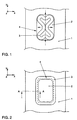
- a sealing tape 3 is preassembled, as shown in FIGS. 1 and 2.
- the sealing tape 3 designed as an annular seal is first folded up and inserted into the wall opening 2. Subsequently, the sealing tape 3, as indicated by the arrows in FIG. 1, is pushed over an opening edge flange 4 of the wall opening 2. 2, the sealing tape 3 is pre-assembled.
- FIG. 3 shows a schematic cross section along the line AA of FIG. 2, from which it can be seen that the sealing strip 3 has a longitudinal recess 5.
- the basic shape of the cross section of this longitudinal recess 5 corresponds approximately to that of an equilateral triangle, the walls of the sealing tape 3 having a first clamping leg 6, a second clamping leg 7 and a connecting wall 8 which connects the first clamping leg 6 and the second clamping leg 7.
- the free ends 13, 14 of the clamping legs 6, 7 adjoin each other in a clamping gap 9.
- the first clamping leg 6 has a convex curvature and at the inner transition to the connecting wall 8 on a locking lug 12.
- the second clamping leg 7 essentially flat and points in the area of the connection of the second Clamp leg 7 on the connecting wall 8 a protruding elevation as a sealing bead 10 on. In the area of this sealing bead 10 is on the inside of the connecting wall 8 Support collar 11 formed.
- the opening edge flange 4 and accordingly the free edge 13 of the second Clamping legs 7 are bent while the free end 14 of the first Clamping leg 6 extends into the cranking edge 15 of the opening edge flange 4.
- the sealing tape 3 can now be used when installing the Air conditioning unit 16 can be folded up manually, as shown in FIGS. 4 and 5 is shown schematically. This prevents the sealing tape 3 when Retracting the heater 16 collides with it.
- FIGS. 4 and 5 the sealing tape 3 is held in this intermediate assembly position via the latching lug 12, which snaps onto the opening edge flange 4 in the folded-up intermediate assembly position.
- 6 schematically shows the assembly of the pollen filter housing 17.
- This pollen filter housing 17 is supplied perpendicular to the wall opening plane coming from the positive Z direction. It then encounters the sealing tape 3, whereby it is pressed down during the further forward movement of the pollen filter housing 17 in such a way that the locking lug 12 disengages from the opening edge flange 4 and thereby folds down the sealing tape 3 into the final assembly position shown schematically in FIG. 7.
- the sealing tape 3 does not have to be folded down by installing the pollen filter housing 17. Alternatively, it can also be folded down by hand or with the aid of a device.
- the sealing tape 3 After attaching the pollen filter housing 17, the sealing tape 3 is as Double seal in its final installation position and takes over the sealing function compared to the air conditioner 16 and the pollen filter housing 17.
- the tolerances are compensated for by the constructively definable overlaps 18 and 19 and the pressure required for sealing between the air conditioner 16 and the Pollen filter housing 17 achieved.
- FIG. 8 to 10 schematically shows a tool 20 for producing the Sealing tape 3 shown.
- This tool 20 is a three-part injection mold, that of a core 21, a first mold half 22 and a second mold half 23 consists.
- the tool 20 further comprises a first ejector pin 24 and one second ejector pin 25.
- the core 21 fills the interior of the Longitudinal recess 5 of the sealing tape 3 and the clamping gap 9 between free Edge 13 and free end 14 of the clamping legs 6, 7.
- the first mold half 22 forms the outside of the second clamping leg 7 and a part of the second Clamping leg adjoining connecting wall 8. This first mold half 22 is can be opened orthogonally to the second clamping leg 7 and the second mold half 23.
- the second mold half 23 forms the remaining outer sides of the first clamping leg 6 and the connecting wall 8.
- the sealing strip 3 in one piece Manufacturing operation.
- the first one runs Mold half 22, as shown in FIG. 9, upwards.
- the core 21 drives the core 21 upwards, as is also shown schematically in FIG. 9.
- the second mold half 23 can also move downwards.
- the one stored in the core 21 first ejector pin 24 moves so that the second clamping leg 7 and part of the Connecting wall 8 can be lifted off the core 21, as shown in FIG. 10 is shown schematically.
- the second ejector pin 25 which is mounted in the first mold half 22, down and lifts the rest of the connecting wall 8 and the first clamping leg 6 from the core from.
Landscapes
- Engineering & Computer Science (AREA)
- Mechanical Engineering (AREA)
- Manufacturing & Machinery (AREA)
- Physics & Mathematics (AREA)
- Thermal Sciences (AREA)
- Gasket Seals (AREA)
- Air-Conditioning For Vehicles (AREA)
- Package Closures (AREA)
- Making Paper Articles (AREA)
- Building Environments (AREA)
Abstract
Description
Die Erfindung betrifft eine Dichtungsanordnung für eine in einer Wand, vorzugsweise
einer Spritzwand einer Karosserie, angebrachte Wandöffnung nach dem Oberbegriff des
Anspruchs 1, ein Werkzeug zur Herstellung eines Dichtungsbandes nach dem
Oberbegriff des Anspruchs 11 und ein Verfahren zur Einbringung einer Dichtung nach
Anspruch 12.The invention relates to a sealing arrangement for a in a wall, preferably
a bulkhead of a body, wall opening according to the preamble of
Es ist im Fahrzeugbau allgemein bekannt an eine in einer Karosseriewand ausgebildete Wandöffnung an den gegenüberliegenden Wandseiten Funktionsteile mit einer entsprechend zugeordneten Funktionsteilöffnung anzuschließen, um so eine Verbindung, z. B. eine Luftverbindung, zwischen den einzelnen Bauteilen herzustellen. Um in den Anschlußbereichen der Funktionsteile an die Karosseriewand die Bauteile gegeneinander bzw. gegen die Umwelt abzudichten, werden diese Funktionsteile mittels wenigstens einer Dichtung im Öffnungsbereich der Karosseriewand angeschlossen.It is generally known in vehicle construction to one designed in a body wall Functional parts with a wall opening on the opposite wall sides to connect correspondingly assigned functional part opening, so as to Connection, e.g. B. create an air connection between the individual components. To the components in the connection areas of the functional parts to the body wall to seal against each other or against the environment, these functional parts are by means of at least one seal connected in the opening area of the body wall.
Ein konkretes Beispiel für eine derartige Anordnung findet sich im Fahrzeugbau z. B. in Verbindung mit dem Einbau von Klima- und/oder Heizgeräten und/oder Pollenfiltergehäusen. Hierfür wird in einer Spritzwand einer Karosserie eine Lufteintrittsöffnung ausgebildet. Bei einigen Fahrzeugtypen befindet sich diese Lufteintrittsöffnung gemäß dem in Deutschland üblichen Fahrzeugkoordinatensystem in einer orthogonal zur in Richtung Dach weisenden Z-Achse liegenden Ebene. Im Bereich unterhalb der Lufteintrittsöffnung wird bei der Montage das Klima- und/oder Heizgerät mittels einer Montagehilfe in negative Richtung der in Richtung Fahrzeugheck weisenden X-Achse in das Fahrzeug eingefahren, d. h. nach Fahrzeug vorne. Um z. B. einen Lecklufteintritt zu verhindern, ist zur Abdichtung eine Dichtung zwischen der Spritzwand und dem Klima- und/oder Heizgerät vorgesehen. Diese Dichtung wird bereits vor dem Einfahren des Klima- und/oder Heizgeräts im Bereich der Lufteintrittsöffnung der Spritzwand vormontiert. Um beim Einfahren ein Kollidieren des Klima- und/oder Heizgeräts mit der vormontierten Dichtung zu vermeiden, werden sogenannte vorkomprimierte Memory-Dichtungen verwendet. Durch dieses Vorkomprimieren steht genügend Raum zur Verfügung, um das Klima- und/oder Heizgerät in das Fahrzeug einzufahren, ohne mit der Dichtung zu kollidieren. Nach dem Einfahren des Klima- und/oder Heizgeräts in das Fahrzeug in die geeignete Anschlußposition im Bereich der Lufteintrittsöffnung entspannt sich die Memory-Dichtung und dichtet das Klima- und/oder Heizgerät ggf. unter Toleranzausgleich gegen die Spritzwand ab.A specific example of such an arrangement can be found in vehicle construction e.g. B. in Connection with the installation of air conditioning and / or heating devices and / or Pollen filter housings. For this purpose, a body is in a bulkhead Air inlet opening formed. This is found on some vehicle types Air inlet opening according to the vehicle coordinate system common in Germany in a plane orthogonal to the Z-axis pointing towards the roof. In the area The air conditioning and / or heating device is installed below the air inlet opening by means of an assembly aid in the negative direction towards the rear of the vehicle X-axis pointing into the vehicle, d. H. after vehicle in front. To z. B. To prevent leakage of air, a seal between the Bulkhead and the air conditioning and / or heater provided. This seal is already before retracting the air conditioning and / or heating device in the area of the air inlet opening the bulkhead pre-assembled. In order to collide the climate and / or when entering Avoiding heaters with the pre-assembled seal are so-called precompressed memory seals used. By this pre-compression stands enough space to place the air conditioner and / or heater in the vehicle to retract without colliding with the seal. After retracting the air conditioning and / or Heater in the vehicle in the appropriate connection position in the area Air inlet opening relaxes the memory seal and seals the climate and / or If necessary, adjust the heater against the bulkhead with tolerance compensation.
Anschließend wird das Pollenfiltergehäuse von oben her, d. h. in negative Z-Richtung, auf die Spritzwand gesetzt und dort verschraubt. Die Abdichtung dieses Pollenfiltergehäuses gegen die Spritzwand erfolgt mittels einer auf das Pollenfiltergehäuse aufgespritzten Schaumdichtung als separate Dichtung.Then the pollen filter housing from above, i. H. in the negative Z direction, placed on the bulkhead and screwed there. Sealing this Pollen filter housing against the bulkhead is made by means of a Pollen filter housing sprayed foam seal as a separate seal.
Bei diesem Aufbau werden somit zwei separate Dichtungen benötigt. Durch die Verwendung einer Memory-Dichtung als vormontierbare Dichtung muß die Montage dieser Memory-Dichtung sowie das darauf erfolgende Einfahren des Heizgeräts in einem engen zeitlichen Abstand vor der Entspannung der Memory-Dichtung erfolgen, was zu einer geringeren Flexibilität bei der Montage der Baugruppen führt.With this construction, two separate seals are therefore required. Through the Using a memory seal as a preassembled seal requires assembly this memory seal as well as the subsequent retraction of the heater in one close time interval before the relaxation of the memory seal, which leads to leads to less flexibility when assembling the modules.
Aufgabe der Erfindung ist es, eine Dichtungsanordnung für eine in einer Wand, vorzugsweise einer Spritzwand einer Karosserie, angebrachte Wandöffnung so weiterzuentwickeln, daß auf einfache und wenig aufwendige Weise eine gute Abdichtung gegen die sich anschließenden Funktionsteile unter gleichzeitigem Toleranzausgleich erreicht wird, weiter ein Werkzeug zur Herstellung eines Dichtungsbandes oder einer Ringdichtung zu schaffen, sowie ein Verfahren zur Einbringung einer Dichtung zwischen mindestens zwei Öffnungen vorzuschlagen.The object of the invention is to provide a sealing arrangement for a in a wall, preferably a bulkhead of a body, wall opening made so further develop that in a simple and inexpensive way a good one Sealing against the subsequent functional parts under simultaneous Tolerance compensation is achieved, further a tool for producing a To create sealing tape or a ring seal, and a method for Propose a seal between at least two openings.
Diese Aufgabe wird bezüglich der Dichtungsanordnung mit den kennzeichnenden
Merkmalen des Anspruchs 1, bezüglich des Werkzeugs mit den Merkmalen des
Anspruchs 11 und bezüglich des Verfahrens mit den Merkmalen des Anspruchs 12
gelöst.This task is carried out with regard to the sealing arrangement with the characteristic
Features of
Nach Anspruch 1 ist ein elastisches Dichtungsband mit einer Längsausnehmung auf
einen Öffnungsrandflansch einer Wandöffnung aufgesteckt. Die Längsausnehmung
weist im Querschnitt eine etwa dreieckige Grundform auf. Die Wände des elastischen
Dichtungsbandes bilden einen ersten Klemmschenkel und einen zweiten
Klemmschenkel, die miteinander durch eine Verbindungswand verbunden sind, wobei
die Klemmschenkel an ihren freien Enden in einem Klemmspalt aneinandergrenzen.
Dadurch ist das mit dem Klemmspalt bis etwa zur Innenseite der Verbindungswand auf
den Öffnungsrandflansch aufgesteckte Dichtungsband in eine Zwischenmontagestellung
klappbar, bei der der erste Klemmschenkel in den Bereich des Öffnungsrandflansches
geklappt ist. In dieser Position des ersten Klemmschenkels ist im Klappbereich des
ersten Klemmschenkels ein Freiraum zur Montage eines Funktionsteils, vorzugsweise
mit einer Montagerichtung etwa parallel zur Ebene des Öffnungsrandflansches, gebildet.
Nach dieser Montage ist das Dichtungsband in eine Endmontagestellung klappbar. In
dieser Endmontagestellung ist der zweite Klemmschenkel in den Bereich des
Öffnungsrandflansches geklappt, wobei der erste Klemmschenkel auf die
Öffnungsrandfläche der Funktionsteilöffnung des Funktionsteils klappbar ist und dort
dichtend anliegt. Bei konvexen Krümmungen der Klemmschenkel kann das
Dichtungsband die Klappfunktion auch bei einem angenäherten Oval- oder
Kreisquerschnitt ermöglichen, so daß auch solche Ausführungen umfaßt sein sollen.According to
Durch die Klappung des elastischen Dichtungsbandes und der damit verbundenen Freiraumschaffung im Klappbereich ist bei vormontierter Dichtung eine Funktionsteilmontage möglich, bei der das Funktionsteil auch ohne die Verwendung einer Memory-Dichtung nicht mit der Dichtung kollidiert: Zudem kann durch das Abklappen des Dichtungsbandes auf einfache Weise eine Dichtfunktion und ein Toleranzausgleich zwischen den Bauteilen erzielt werden. Dies erspart z. B. die Verwendung von aufwendigen Memory-Dichtungen und gewährleistet eine größere Flexibilität im Rahmen der Montage.By folding the elastic sealing tape and the associated Free space in the folding area is one with a pre-assembled seal Functional part assembly possible, in which the functional part also without the use a memory seal does not collide with the seal: In addition, the Fold down the sealing tape in a simple way and a sealing function Tolerance compensation between the components can be achieved. This saves z. B. the Use of elaborate memory seals and ensures a larger one Installation flexibility.
In der Endmontagestellung des elastischen Dichtungsbandes ist in einer vorteilhaften Weiterbildung der Anordnung ein zweites Funktionsteil mit einer Öffnungsrandfläche seiner Funktionsteilöffnung dicht auf den zweiten Klemmschenkel aufsetzbar und in Richtung des Öffnungsrandflansches verspannbar. Dabei wird der erste Klemmschenkel am ersten Funktionsteil dichtend angedrückt. Vorzugsweise wird die Klappung des Dichtungsbandes in die Endmontagestellung durch die Montage des zweiten Funktionsteils bewirkt.In the final assembly position of the elastic sealing tape is advantageous Development of the arrangement of a second functional part with an opening edge area its functional part opening can be placed tightly on the second clamping leg and in Can be clamped in the direction of the opening edge flange. The first clamp leg pressed tightly on the first functional part. Preferably, the folding of the Sealing tape in the final assembly position by assembling the second one Functional part causes.
Das vormontierte elastische Dichtungsband dieser Dichtungsanordnung fungiert hier als Doppeldichtung und stellt eine Abdichtung zu den sich an gegenüberliegenden Wandseiten anschließenden Funktionsteilen dar, ohne daß es hierfür der Anordnung einer separaten Dichtung für jedes Funktionsteil bedarf. Mit einer einzigen Dichtung ist hier somit die Abdichtung dreier Bauteile gegeneinander möglich. Damit können die Teilevielfalt reduziert und gleichzeitig der Montageaufwand verringert werden. The pre-assembled elastic sealing tape of this sealing arrangement acts as Double seal and provides a seal to the opposite ones Functional parts adjoining the wall sides, without this being the case requires a separate seal for each functional part. With a single seal here the sealing of three components against each other is possible. So that can Diversity of parts reduced and at the same time the assembly effort can be reduced.
Die erfindungsgemäße Dichtungsanordnung kann grundsätzlich für jede Wandöffnung Verwendung finden, bei der Funktionsteile mit zugeordneten Funktionsteilöffnungen an Wände mit Wandöffnungen dicht angeschlossen werden sollen. In einer bevorzugten Ausführungsform ist die Wand eine Spritzwand einer Karosserie und das erste Funktionsteil ein Klima- und/oder Heizgerät und das zweite Funktionsteil ein Pollenfilter.The sealing arrangement according to the invention can in principle for each wall opening Find use when functional parts with assigned functional part openings Walls with wall openings should be tightly connected. In a preferred one Embodiment, the wall is a bulkhead of a body and the first Functional part an air conditioning and / or heating device and the second functional part a pollen filter.
Die Längsausnehmung des elastischen Dichtungsbandes weist allgemein eine im Querschnitt in etwa dreieckförmige Grundform auf. In einer bevorzugten Ausführungsform mit guter Klapp- und Dichtfunktion entspricht die Grundform des Querschnitts der Längsausnehmung in etwa der eines gleichseitigen Dreiecks.The longitudinal recess of the elastic sealing tape generally has an im Cross-section in an approximately triangular basic shape. In a preferred one Embodiment with good folding and sealing function corresponds to the basic shape of the Cross-section of the longitudinal recess approximately that of an equilateral triangle.
In einer weiteren vorteilhaften Ausbildung weist der erste Klemmschenkel eine konvexe Wölbung auf und/oder ist der zweite Klemmschenkel eben, wobei im Bereich der Anbindung des zweiten Klemmschenkels an die Verbindungswand eine abstehende Erhebung als Dichtwulst ausgebildet ist. In diesem Anschlußbereich ist ferner vorzugsweise ein innenliegender Stützbund ausgebildet. Über diesen Stützbund ist das Dichtungsband bei Anlage am Öffnungsrandflansch abstützbar, z. B. in der Endmontagestellung bei abgeklapptem Dichtungsband. Gleichzeitig ist jedoch das Verschwenken des Dichtungsbandes aus der Endmontage- in die Zwischenmontagestellung trotz des Stützbundes nach wie vor möglich, da die Abstützung nur in negative Z-Richtung erfolgt.In a further advantageous embodiment, the first clamping leg has a convex shape Curvature on and / or the second clamping leg is flat, being in the area of Connection of the second clamping leg to the connecting wall is a protruding one Elevation is designed as a sealing bead. In this connection area is also preferably an inner support collar is formed. That is about this support covenant Sealing tape can be supported on the edge of the opening flange, e.g. B. in the Final assembly position with the sealing tape folded down. At the same time, however, that is Swiveling the sealing tape from the final assembly into the Intermediate assembly position still possible despite the support collar, as the Support is only in the negative Z direction.
Um das Dichtungsband in der hochgeklappten Lage der Zwischenmontagestellung zu halten und damit den Montagefreiraum herzustellen, kann eine mechanische Hilfsvorrichtung verwendet werden, die sich an der die Wandöffnung aufweisenden Wandung abstützt und die Dichtung hochklappt sowie in dieser Lage hält. Vorzugsweise ist jedoch der Klemmschenkel in dieser hochgeklappten Lage der Zwischenmontagestellung mittels einer Rastnase festgelegt, die am inneren Übergang zwischen erstem Klemmschenkel und Verbindungswand ausgebildet ist. Dadurch kann der Einsatz mechanischer Hilfsvorrichtungen vermieden werden, so daß die für die Montage benötigte Teilevielfalt verringert ist.To the sealing tape in the folded position of the intermediate assembly position hold and thus create the assembly space can be a mechanical Auxiliary device can be used, which on the wall opening Supported wall and folds up the seal and holds it in this position. Preferably However, the clamping leg is in this folded-up position Intermediate assembly position determined by means of a locking lug, which at the inner transition is formed between the first clamping leg and the connecting wall. This can the use of mechanical auxiliary devices can be avoided, so that for the Assembly required parts variety is reduced.
Bevorzugt ist der Öffnungsrandflansch und entsprechend der freie Rand des zweiten Klemmschenkels abgekröpft und reicht das freie Ende des ersten Klemmschenkels bis in die Abkröpfkante des Öffnungsrandflansches. Durch die Abkröpfung des Öffnungsrandflansches und entsprechend des zweiten Klemmschenkels ist eine Abzugsicherung für das Dichtband in X-Richtung, d. h. in Richtung Fahrzeugheck, ausgebildet. Das freie Ende des ersten Klemmschenkels in der Abkröpfkante bildet den Schwenkpunkt des Dichtungsbandes und ist ortsfest.The opening edge flange and correspondingly the free edge of the second is preferred The clamping leg is bent and the free end of the first clamping leg extends up to into the cranking edge of the opening edge flange. By cranking the Opening edge flange and corresponding to the second clamping leg is one Trigger protection for the sealing tape in the X direction, d. H. towards the rear of the vehicle, educated. The free end of the first clamping leg in the cranking edge forms the Pivot point of the sealing tape and is stationary.
In einer weiteren vorzugsweisen Ausgestaltung ist das Dichtungsband als Doppeldichtung zu einer Ringdichtung geschlossen. Dadurch können Wandöffnungen mit einem einzigen Dichtungsband vollständig abgedichtet werden. Das Dichtungsband kann aus jeglichem elastischen Material hergestellt sein. Als bevorzugte Materialien für das Dichtungsband werden Kautschuk oder EPDM oder Kunststoffschaum verwendet.In a further preferred embodiment, the sealing tape is as Double seal closed to form a ring seal. This can create wall openings completely sealed with a single sealing tape. The sealing tape can be made of any elastic material. As preferred materials for the sealing tape, rubber or EPDM or plastic foam are used.
Nach Anspruch 11 ist zur Herstellung eines Dichtungsbandes oder einer Ringdichtung
eine dreiteilige Spritzgußform vorgesehen. Diese Spritzgußform besteht aus einem
Kern, einer ersten Formhälfte und einer zweiten Formhälfte und weist ferner einen
ersten Auswerferstift und einen zweiten Auswerferstift auf. Der Kern dieser dreiteiligen
Spritzgußform füllt den Innenraum der Längsausnehmung und den Klemmspalt aus,
während die erste Formhälfte die Außenseite des zweiten Klemmschenkels und einen
Teil der angrenzenden Verbindungswand bildet und dabei orthogonal zum zweiten
Klemmschenkel und der zweiten Formhälfte öffenbar ist. Die zweite Formhälfte bildet die
übrigen Außenseiten des ersten Klemmschenkels und der Verbindungswand. Mit dem
ersten, im Kern gelagerten Auswerferstift ist der zweite Klemmschenkel und ggf. ein Teil
der Verbindungswand bei geöffneter erster Formhälfte um ca. 90° elastisch aufklappbar
und vom zugeordneten Kernbereich abhebbar. Mit dem zweiten, in der ersten
Formhälfte gelagerten Auswerferstift ist der erste Klemmschenkel und ggf. der restliche
Teil der Verbindungswand entgegen der Öffnungsrichtung vom Kern ablösbar.According to
Mit einem derartigen Werkzeug ist es möglich, ein Dichtungsband oder eine Ringdichtung einteilig in einem einzigen Arbeitsgang herzustellen. Dadurch verringert sich die Herstellungszeit und auch die Kosten für die Herstellung eines derartigen Dichtungsbandes oder Ringdichtung.With such a tool, it is possible to use a sealing tape or a Manufacture ring seal in one piece in a single operation. This reduces the manufacturing time and also the cost of manufacturing such Sealing tape or ring seal.
Nach Anspruch 12 wird ein Verfahren zur Einbringung einer Dichtung zwischen mindestens zwei Öffnungen entlang eines Öffnungsrandflansches einer der Öffnungen mit folgenden drei Verfahrensschritten vorgeschlagen:
- Aufsetzen der Dichtung auf den Öffnungsrandflansch derart, daß bei einem Positionieren der Öffnungen die Dichtung außer Eingriff gehalten wird zu den Öffnungen;
- Positionieren der Öffnungen zueinander;
- In Eingriff bringen der Dichtung bezüglich der Öffnungen.
- Placing the seal on the opening edge flange such that when the openings are positioned, the seal is kept disengaged from the openings;
- Positioning the openings to each other;
- Engaging the seal with respect to the openings.
Mit einem solchen Verfahren werden die Montagemöglichkeiten bei einem Positionieren der Öffnungen vergrößert und ggf. die Montage vereinfacht, da durch die vorerst außer Eingriff gehaltene Dichtung Montagefreiräume geschaffen werden. Erst wenn die Öffnungen positioniert sind, wird dann die Dichtung bezüglich der Öffnungen in Eingriff gebracht.With such a method, the mounting options when positioning the openings are enlarged and the assembly is simplified if necessary, because of the temporary exception Tampering seal assembly clearances are created. Only when the Openings are positioned, the seal is then engaged with respect to the openings brought.
Im ersten Verfahrensschritt kann die Dichtung mit unterschiedlichen Maßnahmen, beispielsweise von Hand vorerst außer Eingriff gehalten werden, vorzugsweise wird dazu jedoch eine mit der Dichtung verbundene Rastnase verwendet.In the first process step, the seal can be For example, be kept out of engagement by hand for the time being, preferably however, a locking lug connected to the seal is used for this.
Besonders vorteilhaft ist das Verfahren verwendbar, wenn das Positionieren von zwei Öffnungen mit einer Positionierrichtung etwa parallel zu den Öffnungsflächen erfolgt, da dazu ein geeigneter Freiraum durch die außer Eingriff gehaltene Dichtung geschaffen wird.The method can be used particularly advantageously if the positioning of two Openings with a positioning direction take place approximately parallel to the opening surfaces, since a suitable free space is created by the disengaged seal becomes.
Das Verfahren ist besonders gut zur Abdichtung zwischen drei zueinander zu positionierenden Öffnungen geeignet, wobei dann die Dichtung als Doppeldichtung wirkt und der dritte Verfahrensschritt durch das Positionieren der dritten Öffnung durchführbar ist.The method is particularly good for sealing between three to each other Positioning openings suitable, in which case the seal acts as a double seal and the third method step can be carried out by positioning the third opening is.
Dabei kann durch das Positionieren der dritten Öffnung die Dichtung mit einem Stützbund am Rand der ersten Öffnung abgestützt werden, wodurch insbesondere die Elastizität und Anlagekraft der Dichtung bezüglich der Öffnungen beeinflußbar ist. Ein besonders geeigneter Anwendungsbereich für das Verfahren ist die Abdichtung von Luftdurchtrittöffnungen bei Komponenten einer Heizung- und/oder Kühlung- und/oder Klimaanlage eines Kraftfahrzeugs.By positioning the third opening, the seal can be closed with a Support collar are supported on the edge of the first opening, which in particular the Elasticity and contact force of the seal with respect to the openings can be influenced. On A particularly suitable area of application for the method is the sealing of Air passage openings in components of a heating and / or cooling and / or Air conditioning system of a motor vehicle.
Anhand einer Zeichnung wird die Erfindung näher erläutert.The invention is explained in more detail with reference to a drawing.
Es zeigen:
- Fig. 1
- eine schematische Darstellung einer Spritzwand einer Karosserie mit Wandöffnung und darin eingeführtem Dichtungsband,
- Fig. 2
- eine schematische Darstellung einer Spritzwand einer Karosserie mit vormontiertem Dichtungsband als Ringdichtung,
- Fig. 3
- einen schematischen Querschnitt einer Dichtungsanordnung mit vormontiertem Dichtungsband entlang der Linie A-A der Fig. 2,
- Fig. 4
- einen schematischen Querschnitt einer Dichtungsanordnung mit in eine Zwischenmontagestellung hochgeklapptem Dichtungsband,
- Fig. 5
- einen schematischen Querschnitt einer Dichtungsanordnung mit vormontiertem Dichtungsband in einer Zwischenmontagestellung des Dichtungsbandes während des Einfahrens eines Klimagerätes als Funktionsteil,
- Fig. 6
- einen schematischen Querschnitt einer Dichtungsanordnung zu Beginn des Übergangs von der Zwischenmontagestellung in die Endmontagestellung,
- Fig. 7
- einen schematischen Querschnitt einer Dichtungsanordnung in der Endmontagestellung,
- Fig. 8
- eine schematische Darstellung eines Werkzeugs zur Herstellung eines Dichtungsbandes oder einer Ringdichtung unmittelbar nach dem Gießen,
- Fig. 9
- eine schematische Darstellung eines Werkzeugs zur Herstellung eines Dichtungsbandes oder einer Ringdichtung mit nach oben gefahrenen Werkzeugteilen zu Beginn einer ersten Auswurfbewegung, und
- Fig. 10
- eine schematische Darstellung eines Werkzeugs zur Herstellung eines Dichtungsbandes oder einer Ringdichtung mit teilweise ausgeworfenem Dichtungsband.
- Fig. 1
- 1 shows a schematic illustration of a bulkhead of a body with a wall opening and a sealing tape inserted therein,
- Fig. 2
- 1 shows a schematic representation of a bulkhead of a body with a preassembled sealing tape as a ring seal,
- Fig. 3
- 2 shows a schematic cross section of a sealing arrangement with a preassembled sealing tape along the line AA in FIG. 2,
- Fig. 4
- 2 shows a schematic cross section of a sealing arrangement with the sealing tape folded up into an intermediate assembly position,
- Fig. 5
- 1 shows a schematic cross section of a sealing arrangement with a preassembled sealing tape in an intermediate assembly position of the sealing tape during the retraction of an air conditioner as a functional part,
- Fig. 6
- 2 shows a schematic cross section of a sealing arrangement at the beginning of the transition from the intermediate assembly position into the final assembly position,
- Fig. 7
- 1 shows a schematic cross section of a sealing arrangement in the final assembly position,
- Fig. 8
- 1 shows a schematic illustration of a tool for producing a sealing tape or a ring seal immediately after casting,
- Fig. 9
- a schematic representation of a tool for producing a sealing tape or a ring seal with tool parts moved upwards at the beginning of a first ejection movement, and
- Fig. 10
- is a schematic representation of a tool for producing a sealing tape or a ring seal with partially ejected sealing tape.
Anhand der Fig. 1 bis 7 wird die Verwendung der erfindungsgemäßen
Dichtungsanordnung in Verbindung mit dem Anschluß eines Klimagerätes 16 sowie
eines Pollenfiltergehäuses 17 mit deren Geräteöffnungen an eine Wandöffnung 2 einer
Spritzwand 1 erläutert, wobei die Wandöffnung 2 in einer durch die Y- und X-Achse
eines in Deutschland üblichen Fahrzeugkoordinatensystems aufgespannten Ebene
liegen. Dabei weist die X-Achse in Richtung Fahrzeugheck, die Y-Achse in Richtung
Beifahrerseite und eine Z-Achse in Richtung Dach. An die Wandöffnung 2 soll nach
oben hin, d. h. in positive Z-Richtung, das Pollenfiltergehäuse 17 und nach unten hin,
d. h. in negative Z-Richtung, das Klimagerät 16 durch Einfahren in negative X-Richtung
dicht angeschlossen werden.1 to 7 the use of the invention
Sealing arrangement in connection with the connection of an
In einem ersten Montageschritt wird ein Dichtungsband 3 vormontiert, wie dies in den
Fig. 1 und 2 dargestellt ist. Dazu wird zuerst das als Ringdichtung ausgebildete
Dichtungsband 3 zusammengefaltet und in die Wandöffnung 2 eingeführt. Anschließend
wird das Dichtungsband 3, wie dies in der Fig. 1 durch die Pfeile gekennzeichnet ist,
über einen Öffnungsrandflansch 4 der Wandöffnung 2 geschoben. In der Fig. 2 ist das
Dichtungsband 3 fertig vormontiert.
In der Fig. 3 ist ein schematischer Querschnitt entlang der Linie A-A der Fig. 2
dargestellt, aus dem ersichtlich ist, daß das Dichtungsband 3 eine Längsausnehmung 5
aufweist. Die Grundform des Querschnitts dieser Längsausnehmung 5 entspricht in etwa
der eines gleichseitigen Dreiecks, wobei die Wände des Dichtungsbandes 3 einen
ersten Klemmschenkel 6, einen zweiten Klemmschenkel 7 und eine Verbindungswand 8
aufweisen, die den ersten Klemmschenkel 6 und den zweiten Klemmschenkel 7
verbindet. Die freien Enden 13, 14 der Klemmschenkel 6, 7 grenzen dabei in einem
Klemmspalt 9 aneinander.In a first assembly step, a sealing
FIG. 3 shows a schematic cross section along the line AA of FIG. 2, from which it can be seen that the sealing
Der erste Klemmschenkel 6 weist eine konvexe Wölbung sowie am inneren Übergang
zur Verbindungswand 8 eine Rastnase 12 auf. Dagegen ist der zweite Klemmschenkel 7
im wesentlichen eben ausgebildet und weist im Bereich der Anbindung des zweiten
Klemmschenkels 7 an die Verbindungswand 8 eine abstehende Erhebung als Dichtwulst
10 auf. Im Bereich dieses Dichtwulstes 10 ist an der Verbindungswand 8 innen ein
Stützbund 11 ausgebildet.The
Der Öffnungsrandflansch 4 und entsprechend der freie Rand 13 des zweiten
Klemmschenkels 7 sind abgekröpft, während das freie Ende 14 des ersten
Klemmschenkels 6 bis in die Abkröpfkante 15 des Öffnungsrandflansches 4 reicht.The opening
Durch die Abkröpfung des Öffnungsrandflansches 4 und des freien Rands 13 des
zweiten Klemmschenkels 7 wird eine Abzugsicherung in X-Richtung hergestellt.
Andererseits wird durch den Stützbund 11 eine Verschiebung des Dichtungsbandes 3 in
negative Z-Richtung verhindert. Das freie Ende 14 ist ortsfest und bildet in der
Abkröpfkante den Schwenkpunkt des Dichtungsbandes 3. By cranking the opening
Ausgehend von der vormontierten Grundstellung des Dichtungsbandes 3, wie sie in der
Fig. 3 dargestellt ist, kann nunmehr das Dichtungsband 3 bei der Montage des
Klimagerätes 16 manuell hochgeklappt werden, wie dies in den Fig. 4 und 5
schematisch dargestellt ist. Damit wird verhindert, daß das Dichtungsband 3 beim
Einfahren des Heizgerätes 16 mit diesem kollidiert.Starting from the pre-assembled basic position of the sealing
Wie dies in den Fig. 4 und 5 weiter dargestellt ist, wird das Dichtungsband 3 in dieser
Zwischenmontagestellung über die Rastnase 12, die in der hochgeklappten
Zwischenmontagestellung am Öffnungsrandflansch 4 einschnappt, gehalten. Auf diese
Weise ist eine zeitweise Entkopplung zwischen dem Dichtungsband 3 und dem
Klimagerät 16 gegeben.
In der Fig. 6 ist schematisch die Montage des Pollenfiltergehäuses 17 dargestellt.
Dieses Pollenfiltergehäuse 17 wird senkrecht zur Wandöffnungsebene von der positiven
Z-Richtung kommend zugeführt. Es stößt dann auf das Dichtungsband 3, wodurch diese
bei der weiteren Vorwärtsbewegung des Pollenfiltergehäuses 17 so heruntergedrückt
wird, daß die Rastnase 12 außer Eingriff mit dem Öffnungsrandflansch 4 gelangt und
dadurch das Dichtungsband 3 in die in der Fig. 7 schematisch dargestellte
Endmontagestellung herunterklappt. Das Herunterklappen des Dichtungsbandes 3 muß
nicht zwingend durch die Montage des Pollenfiltergehäuses 17 erfolgen. Alternativ ist
hier auch das Herunterklappen von Hand oder mit Hilfe einer Vorrichtung möglich.As is further shown in FIGS. 4 and 5, the sealing
6 schematically shows the assembly of the
Nach dem Befestigen des Pollenfiltergehäuses 17 liegt das Dichtungsband 3 als
Doppeldichtung in ihrer endgültigen Einbaulage und übernimmt die Dichtungsfunktion
gegenüber dem Klimagerät 16 und dem Pollenfiltergehäuse 17.After attaching the
Durch die konstruktiv bestimmbaren Überschnitte 18 und 19 wird der Toleranzausgleich
und die zur Dichtung nötige Pressung zwischen dem Klimagerät 16 und dem
Pollenfiltergehäuse 17 erzielt.The tolerances are compensated for by the constructively
In den Fig. 8 bis 10 ist schematisch ein Werkzeug 20 zur Herstellung des
Dichtungsbandes 3 dargestellt. Dieses Werkzeug 20 ist eine dreiteilige Spritzgußform,
die aus einem Kern 21, einer ersten Formhälfte 22 sowie einer zweiten Formhälfte 23
besteht. Ferner umfaßt das Werkzeug 20 einen ersten Auswerferstift 24 und einen
zweiten Auswerferstift 25.8 to 10 schematically shows a
Wie dies in der Fig. 8 schematisch dargestellt ist, füllt der Kern 21 den Innenraum der
Längsausnehmung 5 des Dichtungsbandes 3 sowie den Klemmspalt 9 zwischen freiem
Rand 13 und freiem Ende 14 der Klemmschenkel 6, 7 aus. Die erste Formhälfte 22
bildet die Außenseite des zweiten Klemmschenkels 7 und eines Teils der an den zweiten
Klemmschenkel angrenzenden Verbindungswand 8. Diese erste Formhälfte 22 ist
orthogonal zum zweiten Klemmschenkel 7 und der zweiten Formhälfte 23 öffenbar.As shown schematically in FIG. 8, the
Die zweite Formhälfte 23 bildet die übrigen Außenseiten des ersten Klemmschenkels 6
und der Verbindungswand 8.The
Mit dem Werkzeug 20 ist es möglich, das Dichtungsband 3 einteilig in einem
Arbeitsgang herzustellen. Nach erfolgtem Spritzgußvorgang fährt zunächst die erste
Formhälfte 22, wie dies in der Fig. 9 dargestellt ist, nach oben. Im Anschluß daran fährt
der Kern 21 nach oben, wie dies ebenfalls in der Fig. 9 schematisch dargestellt ist.
Alternativ dazu kann auch die zweite Formhälfte 23 nach unten abfahren.With the
Zum Ablösen des Dichtungsbandes 3 von dem Kern 21 wird der im Kern 21 gelagerte
erste Auswerferstift 24 bewegt, so daß der zweite Klemmschenkel 7 und ein Teil der
Verbindungswand 8 von dem Kern 21 abgehoben werden, wie dies in der Fig. 10
schematisch dargestellt ist.To remove the sealing
Anschließend fährt, wie dies ebenfalls in der Fig. 10 schematisch dargestellt ist, der
zweite Auswerferstift 25, der in der ersten Formhälfte 22 gelagert ist, nach unten und
hebt den Rest der Verbindungswand 8 und den ersten Klemmschenkel 6 von dem Kern
ab. Then, as is also shown schematically in FIG. 10, the
- 11
- SpritzwandBulkhead
- 22nd
- WandöffnungWall opening
- 33rd
- DichtungsbandSealing tape
- 44th
- ÖffnungsrandflanschOpening edge flange
- 55
- LängsausnehmungLongitudinal recess
- 66
- erster Klemmschenkelfirst clamping leg
- 77
- zweiter Klemmschenkelsecond clamping leg
- 88th
- VerbindungswandConnecting wall
- 99
- KlemmspaltClamping gap
- 1010th
- DichtwulstSealing bead
- 1111
- StützbundSupport collar
- 1212th
- RastnaseLatch
- 1313
- freier Rand des zweiten Klemmschenkelsfree edge of the second clamping leg
- 1414
- freies Ende des ersten Klemmschenkelsfree end of the first clamping leg
- 1515
- AbkröpfkanteCranking edge
- 1616
- KlimagerätAir conditioner
- 1717th
- PollenfiltergehäusePollen filter housing
- 1818th
- ÜberschnittOverlap
- 1919th
- ÜberschnittOverlap
- 2020th
- WerkzeugTool
- 2121
- Kerncore
- 2222
- erste Formhälftefirst half of the mold
- 2323
- zweite Formhälftesecond mold half
- 2424th
- erster Auswerferstiftfirst ejector pin
- 2525th
- zweiter Auswerterstiftsecond evaluation pin
Claims (17)
an die an einer Wandseite ein Funktionsteil mit einer zugeordneten Funktionsteilöffnung dicht angeschlossen ist,
dadurch gekennzeichnet,
to which a functional part with an assigned functional part opening is tightly connected on one wall side,
characterized,
dadurch gekennzeichnet,
wobei der Kern (21) den Innenraum der Längsausnehmung (5) und den Klemmspalt (9) ausfüllt,
characterized,
wherein the core (21) fills the interior of the longitudinal recess (5) and the clamping gap (9),
Applications Claiming Priority (2)
| Application Number | Priority Date | Filing Date | Title |
|---|---|---|---|
| DE19857077 | 1998-12-10 | ||
| DE19857077A DE19857077A1 (en) | 1998-12-10 | 1998-12-10 | Sealing arrangement for a wall opening, tool for producing a sealing tape and method for introducing a seal |
Publications (3)
| Publication Number | Publication Date |
|---|---|
| EP1008470A2 true EP1008470A2 (en) | 2000-06-14 |
| EP1008470A3 EP1008470A3 (en) | 2002-09-04 |
| EP1008470B1 EP1008470B1 (en) | 2004-03-31 |
Family
ID=7890666
Family Applications (1)
| Application Number | Title | Priority Date | Filing Date |
|---|---|---|---|
| EP99121932A Expired - Lifetime EP1008470B1 (en) | 1998-12-10 | 1999-11-08 | Sealing device for an opening in a panel, tool for making a sealing band and method for fitting a sealing device |
Country Status (3)
| Country | Link |
|---|---|
| EP (1) | EP1008470B1 (en) |
| AT (1) | ATE263040T1 (en) |
| DE (2) | DE19857077A1 (en) |
Family Cites Families (6)
| Publication number | Priority date | Publication date | Assignee | Title |
|---|---|---|---|---|
| EP0245894B1 (en) * | 1986-05-13 | 1990-03-07 | Eurotool B.V. | Container having a detachably fastened lid |
| DE3807840C1 (en) * | 1988-03-10 | 1989-08-03 | Daimler-Benz Aktiengesellschaft, 7000 Stuttgart, De | Bushing for lines, such as cables or tubes, through a wall opening |
| JPH07102581B2 (en) * | 1990-11-17 | 1995-11-08 | 大協株式会社 | Mold structure for plastic molding |
| DE9203455U1 (en) * | 1992-03-14 | 1992-04-30 | Behr GmbH & Co, 7000 Stuttgart | Sealing arrangement for a housing flange |
| US5659924A (en) * | 1994-01-28 | 1997-08-26 | Chemcast Corporation | Grommet with flexible sealing passage |
| DE29807815U1 (en) * | 1998-04-30 | 1998-08-27 | Kromberg & Schubert, 42389 Wuppertal | Elastomer grommet for sealing a wall opening serving as a passage for a strand, in particular for cable bushings in vehicles |
-
1998
- 1998-12-10 DE DE19857077A patent/DE19857077A1/en not_active Withdrawn
-
1999
- 1999-11-08 AT AT99121932T patent/ATE263040T1/en not_active IP Right Cessation
- 1999-11-08 EP EP99121932A patent/EP1008470B1/en not_active Expired - Lifetime
- 1999-11-08 DE DE59909025T patent/DE59909025D1/en not_active Expired - Lifetime
Non-Patent Citations (1)
| Title |
|---|
| None |
Also Published As
| Publication number | Publication date |
|---|---|
| DE19857077A1 (en) | 2000-06-15 |
| EP1008470B1 (en) | 2004-03-31 |
| ATE263040T1 (en) | 2004-04-15 |
| DE59909025D1 (en) | 2004-05-06 |
| EP1008470A3 (en) | 2002-09-04 |
Similar Documents
| Publication | Publication Date | Title |
|---|---|---|
| DE19629115C2 (en) | Process for the production of a forced ventilation for motor vehicles and a forced ventilation for motor vehicles | |
| EP1187734B1 (en) | Vehicle door with door casing and method for the production thereof | |
| EP2024222B1 (en) | Fender module | |
| EP0633153B1 (en) | Process for producing a heating or air-conditioning device with a damper with a housing wall seal, in particular for a motor vehicule | |
| DE10109176A1 (en) | Cross strut arrangement made of plastic for a vehicle with shaft connectors formed uniformly with it | |
| DE102008021717A1 (en) | Roof rail with shaped end | |
| EP0876942A2 (en) | Airbag module for a vehicle passenger restraining system | |
| DE10146694B4 (en) | Cladding element for the roof of a vehicle interior | |
| DE102007059357A1 (en) | Socket and method for its manufacture | |
| DE19730095A1 (en) | Decorative trim for motor vehicle bodywork | |
| DE19620538A1 (en) | Foam cover for air bag in vehicle | |
| DE102016219474A1 (en) | Actuator and method for producing an actuator | |
| DE10103402B4 (en) | Exterior rearview mirror of a motor vehicle | |
| EP1889749A1 (en) | Decorative panel | |
| DE20103892U1 (en) | Vehicle interior trim | |
| EP1008470B1 (en) | Sealing device for an opening in a panel, tool for making a sealing band and method for fitting a sealing device | |
| DE102005036910B4 (en) | Arrangement with a functional part housing and an attachable panel on a motor vehicle | |
| DE202013012309U1 (en) | Connecting arrangement for connecting a support member with a trim part | |
| WO2007079744A1 (en) | Connecting device for at least one guide tube to at least one guide rail, especially of a sliding roof | |
| EP3450777A1 (en) | Method for the connection of at least two components | |
| DE102021111776A1 (en) | BLIND MOUNTING FASTENING SYSTEM | |
| DE29801871U1 (en) | Airbag module for a head protection airbag | |
| DE102024118395A1 (en) | SEAT GROMMET | |
| DE102019208787A1 (en) | Fastening arrangement for a window slot strip | |
| DE112020003702B4 (en) | SUN VISOR FOR A VEHICLE AND METHOD OF ASSEMBLY |
Legal Events
| Date | Code | Title | Description |
|---|---|---|---|
| PUAI | Public reference made under article 153(3) epc to a published international application that has entered the european phase |
Free format text: ORIGINAL CODE: 0009012 |
|
| AK | Designated contracting states |
Kind code of ref document: A2 Designated state(s): AT BE CH CY DE DK ES FI FR GB GR IE IT LI LU MC NL PT SE |
|
| AX | Request for extension of the european patent |
Free format text: AL;LT;LV;MK;RO;SI |
|
| PUAL | Search report despatched |
Free format text: ORIGINAL CODE: 0009013 |
|
| AK | Designated contracting states |
Kind code of ref document: A3 Designated state(s): AT BE CH CY DE DK ES FI FR GB GR IE IT LI LU MC NL PT SE |
|
| AX | Request for extension of the european patent |
Free format text: AL;LT;LV;MK;RO;SI |
|
| RIC1 | Information provided on ipc code assigned before grant |
Free format text: 7B 60H 1/00 A, 7B 29C 45/44 B |
|
| 17P | Request for examination filed |
Effective date: 20030304 |
|
| AKX | Designation fees paid |
Designated state(s): AT BE CH CY DE DK ES FI FR GB GR IE IT LI LU MC NL PT SE |
|
| GRAP | Despatch of communication of intention to grant a patent |
Free format text: ORIGINAL CODE: EPIDOSNIGR1 |
|
| 17Q | First examination report despatched |
Effective date: 20030716 |
|
| GRAS | Grant fee paid |
Free format text: ORIGINAL CODE: EPIDOSNIGR3 |
|
| GRAA | (expected) grant |
Free format text: ORIGINAL CODE: 0009210 |
|
| AK | Designated contracting states |
Kind code of ref document: B1 Designated state(s): AT BE CH CY DE DK ES FI FR GB GR IE IT LI LU MC NL PT SE |
|
| PG25 | Lapsed in a contracting state [announced via postgrant information from national office to epo] |
Ref country code: NL Free format text: LAPSE BECAUSE OF FAILURE TO SUBMIT A TRANSLATION OF THE DESCRIPTION OR TO PAY THE FEE WITHIN THE PRESCRIBED TIME-LIMIT Effective date: 20040331 Ref country code: IT Free format text: LAPSE BECAUSE OF FAILURE TO SUBMIT A TRANSLATION OF THE DESCRIPTION OR TO PAY THE FEE WITHIN THE PRESCRIBED TIME-LIMIT;WARNING: LAPSES OF ITALIAN PATENTS WITH EFFECTIVE DATE BEFORE 2007 MAY HAVE OCCURRED AT ANY TIME BEFORE 2007. THE CORRECT EFFECTIVE DATE MAY BE DIFFERENT FROM THE ONE RECORDED. Effective date: 20040331 Ref country code: IE Free format text: LAPSE BECAUSE OF FAILURE TO SUBMIT A TRANSLATION OF THE DESCRIPTION OR TO PAY THE FEE WITHIN THE PRESCRIBED TIME-LIMIT Effective date: 20040331 Ref country code: GB Free format text: LAPSE BECAUSE OF FAILURE TO SUBMIT A TRANSLATION OF THE DESCRIPTION OR TO PAY THE FEE WITHIN THE PRESCRIBED TIME-LIMIT Effective date: 20040331 Ref country code: FR Free format text: LAPSE BECAUSE OF FAILURE TO SUBMIT A TRANSLATION OF THE DESCRIPTION OR TO PAY THE FEE WITHIN THE PRESCRIBED TIME-LIMIT Effective date: 20040331 Ref country code: FI Free format text: LAPSE BECAUSE OF FAILURE TO SUBMIT A TRANSLATION OF THE DESCRIPTION OR TO PAY THE FEE WITHIN THE PRESCRIBED TIME-LIMIT Effective date: 20040331 Ref country code: ES Free format text: LAPSE BECAUSE OF FAILURE TO SUBMIT A TRANSLATION OF THE DESCRIPTION OR TO PAY THE FEE WITHIN THE PRESCRIBED TIME-LIMIT Effective date: 20040331 Ref country code: CY Free format text: LAPSE BECAUSE OF FAILURE TO SUBMIT A TRANSLATION OF THE DESCRIPTION OR TO PAY THE FEE WITHIN THE PRESCRIBED TIME-LIMIT Effective date: 20040331 |
|
| REG | Reference to a national code |
Ref country code: GB Ref legal event code: FG4D Free format text: NOT ENGLISH Ref country code: CH Ref legal event code: EP |
|
| REG | Reference to a national code |
Ref country code: IE Ref legal event code: FG4D Free format text: GERMAN |
|
| REF | Corresponds to: |
Ref document number: 59909025 Country of ref document: DE Date of ref document: 20040506 Kind code of ref document: P |
|
| PG25 | Lapsed in a contracting state [announced via postgrant information from national office to epo] |
Ref country code: SE Free format text: LAPSE BECAUSE OF FAILURE TO SUBMIT A TRANSLATION OF THE DESCRIPTION OR TO PAY THE FEE WITHIN THE PRESCRIBED TIME-LIMIT Effective date: 20040630 Ref country code: GR Free format text: LAPSE BECAUSE OF FAILURE TO SUBMIT A TRANSLATION OF THE DESCRIPTION OR TO PAY THE FEE WITHIN THE PRESCRIBED TIME-LIMIT Effective date: 20040630 Ref country code: DK Free format text: LAPSE BECAUSE OF FAILURE TO SUBMIT A TRANSLATION OF THE DESCRIPTION OR TO PAY THE FEE WITHIN THE PRESCRIBED TIME-LIMIT Effective date: 20040630 |
|
| GBV | Gb: ep patent (uk) treated as always having been void in accordance with gb section 77(7)/1977 [no translation filed] |
Effective date: 20040331 |
|
| NLV1 | Nl: lapsed or annulled due to failure to fulfill the requirements of art. 29p and 29m of the patents act | ||
| PG25 | Lapsed in a contracting state [announced via postgrant information from national office to epo] |
Ref country code: LU Free format text: LAPSE BECAUSE OF NON-PAYMENT OF DUE FEES Effective date: 20041108 Ref country code: AT Free format text: LAPSE BECAUSE OF NON-PAYMENT OF DUE FEES Effective date: 20041108 |
|
| PG25 | Lapsed in a contracting state [announced via postgrant information from national office to epo] |
Ref country code: MC Free format text: LAPSE BECAUSE OF NON-PAYMENT OF DUE FEES Effective date: 20041130 Ref country code: LI Free format text: LAPSE BECAUSE OF NON-PAYMENT OF DUE FEES Effective date: 20041130 Ref country code: CH Free format text: LAPSE BECAUSE OF NON-PAYMENT OF DUE FEES Effective date: 20041130 Ref country code: BE Free format text: LAPSE BECAUSE OF NON-PAYMENT OF DUE FEES Effective date: 20041130 |
|
| REG | Reference to a national code |
Ref country code: IE Ref legal event code: FD4D |
|
| PLBE | No opposition filed within time limit |
Free format text: ORIGINAL CODE: 0009261 |
|
| STAA | Information on the status of an ep patent application or granted ep patent |
Free format text: STATUS: NO OPPOSITION FILED WITHIN TIME LIMIT |
|
| EN | Fr: translation not filed | ||
| 26N | No opposition filed |
Effective date: 20050104 |
|
| BERE | Be: lapsed |
Owner name: *VOLKSWAGEN A.G. Effective date: 20041130 |
|
| REG | Reference to a national code |
Ref country code: CH Ref legal event code: PL |
|
| BERE | Be: lapsed |
Owner name: *VOLKSWAGEN A.G. Effective date: 20041130 |
|
| PG25 | Lapsed in a contracting state [announced via postgrant information from national office to epo] |
Ref country code: PT Free format text: LAPSE BECAUSE OF NON-PAYMENT OF DUE FEES Effective date: 20040831 |
|
| PGFP | Annual fee paid to national office [announced via postgrant information from national office to epo] |
Ref country code: DE Payment date: 20101130 Year of fee payment: 12 |
|
| REG | Reference to a national code |
Ref country code: DE Ref legal event code: R119 Ref document number: 59909025 Country of ref document: DE Effective date: 20130601 |
|
| PG25 | Lapsed in a contracting state [announced via postgrant information from national office to epo] |
Ref country code: DE Free format text: LAPSE BECAUSE OF NON-PAYMENT OF DUE FEES Effective date: 20130601 |