EP1008491A2 - Kupplungsgebundener Fahrzeugheckträger - Google Patents
Kupplungsgebundener Fahrzeugheckträger Download PDFInfo
- Publication number
- EP1008491A2 EP1008491A2 EP99123708A EP99123708A EP1008491A2 EP 1008491 A2 EP1008491 A2 EP 1008491A2 EP 99123708 A EP99123708 A EP 99123708A EP 99123708 A EP99123708 A EP 99123708A EP 1008491 A2 EP1008491 A2 EP 1008491A2
- Authority
- EP
- European Patent Office
- Prior art keywords
- cross member
- vehicle rear
- rack according
- carrier
- arms
- Prior art date
- Legal status (The legal status is an assumption and is not a legal conclusion. Google has not performed a legal analysis and makes no representation as to the accuracy of the status listed.)
- Granted
Links
- 230000008878 coupling Effects 0.000 claims abstract description 30
- 238000010168 coupling process Methods 0.000 claims abstract description 30
- 238000005859 coupling reaction Methods 0.000 claims abstract description 30
- 238000010276 construction Methods 0.000 claims abstract description 13
- 230000033001 locomotion Effects 0.000 claims description 19
- 230000007246 mechanism Effects 0.000 claims description 8
- 238000006073 displacement reaction Methods 0.000 claims description 2
- 238000005452 bending Methods 0.000 description 3
- 239000000969 carrier Substances 0.000 description 3
- 238000009415 formwork Methods 0.000 description 3
- 238000005253 cladding Methods 0.000 description 2
- 239000002131 composite material Substances 0.000 description 2
- 229920000049 Carbon (fiber) Polymers 0.000 description 1
- 229910052782 aluminium Inorganic materials 0.000 description 1
- XAGFODPZIPBFFR-UHFFFAOYSA-N aluminium Chemical compound [Al] XAGFODPZIPBFFR-UHFFFAOYSA-N 0.000 description 1
- 230000005540 biological transmission Effects 0.000 description 1
- 239000004917 carbon fiber Substances 0.000 description 1
- 230000003292 diminished effect Effects 0.000 description 1
- 230000002349 favourable effect Effects 0.000 description 1
- 239000003365 glass fiber Substances 0.000 description 1
- 238000005286 illumination Methods 0.000 description 1
- 238000007373 indentation Methods 0.000 description 1
- 229910052751 metal Inorganic materials 0.000 description 1
- 239000002184 metal Substances 0.000 description 1
- VNWKTOKETHGBQD-UHFFFAOYSA-N methane Chemical compound C VNWKTOKETHGBQD-UHFFFAOYSA-N 0.000 description 1
- 125000006850 spacer group Chemical group 0.000 description 1
- 230000001360 synchronised effect Effects 0.000 description 1
- 238000003466 welding Methods 0.000 description 1
Images


Classifications
-
- B—PERFORMING OPERATIONS; TRANSPORTING
- B60—VEHICLES IN GENERAL
- B60R—VEHICLES, VEHICLE FITTINGS, OR VEHICLE PARTS, NOT OTHERWISE PROVIDED FOR
- B60R9/00—Supplementary fittings on vehicle exterior for carrying loads, e.g. luggage, sports gear or the like
- B60R9/06—Supplementary fittings on vehicle exterior for carrying loads, e.g. luggage, sports gear or the like at vehicle front or rear
-
- B—PERFORMING OPERATIONS; TRANSPORTING
- B60—VEHICLES IN GENERAL
- B60R—VEHICLES, VEHICLE FITTINGS, OR VEHICLE PARTS, NOT OTHERWISE PROVIDED FOR
- B60R9/00—Supplementary fittings on vehicle exterior for carrying loads, e.g. luggage, sports gear or the like
- B60R9/08—Supplementary fittings on vehicle exterior for carrying loads, e.g. luggage, sports gear or the like specially adapted for sports gear
- B60R9/10—Supplementary fittings on vehicle exterior for carrying loads, e.g. luggage, sports gear or the like specially adapted for sports gear for cycles
Definitions
- the present invention relates to a vehicle rear carrier clutch-based design according to the preamble of Claim 1.
- DB-PS 43 37 006 C2 is a device for transporting loads Motor vehicles with ball head couplings are known.
- This The device has i.a. a coupling element, which with the Ball head of a vehicle towbar engaged can be brought and is shaped such that the Transport device fixed on the ball head so that it cannot tilt or turn can be.
- the device itself consists essentially of one single telescopic support arm in the form of a hollow profile that one end is welded to the coupling element.
- the Telescopic support arm has a large-diameter support tube, in which at least one further small-diameter support tube can be pulled out used and guided axially.
- there is a support tube with the larger one Diameter a locking device in the form of two Clamping screws provided against the small diameter Carrier tube can be created, thus the relative position to fix both support tubes.
- the device described above is intended for if necessary, i.e. in the case of transporting a load in Vehicle longitudinal direction to be pulled out, so one sufficient support area along the telescopic support arm to deliver.
- the device i.e. the two support tubes are telescopically pushed together to achieve smaller and more compact dimensions.
- the so collapsed device projects less over the The rear of the vehicle is off and is less disruptive to normal Driving operation especially when parking and the like Reverse maneuvers.
- the telescopic version of the support arm is cheap in that than that all attachments or superstructures connected to the Support tubes are welded in only one direction, namely in Vehicle longitudinal direction move and thus always in the correct relative position to each other.
- the telescope structure however requires exact guidance to be on the move unpleasant rattling and vibrating of the device avoid and a jamming of the movable Prevent support tubes.
- Rear arrangement of the device also results in heavy pollution hurled road dirt, which the Can disable the telescopic mechanism.
- the telescopic mechanism allows a reduction in size, this However, a reduction is set when the arrival or departure Superstructures on the telescopic support tubes come to lie immediately one after the other.
- the clutch-bound vehicle rear carrier according to the invention has consequently a mountable to a vehicle clutch Coupling element connected to a main cross member in its Middle section is preferably fixed by welding.
- Coupling elements of this type generally consist of two spherical half-shells which can be pressed together via a manually operated lever mechanism and thereby clamp the ball head of the vehicle coupling between them, and an adjustable support device, ie a so-called neck fork, which can be brought into engagement with the coupling neck of the vehicle coupling and the support structure can be adjusted , ie it can be folded down manually without the coupling having to be released.
- an adjustable support device ie a so-called neck fork
- the space necessary for pivoting the linkage is used by the main cross member Vehicle width created so that the invention Vehicle rear rack only slightly when folded cantilevered to the rear.
- each joint linkage consists of at least a first Support arm consists of one at its inner end over a first hinge joint at the respective end section of the Main cross member is articulated, and its pivot plane in is essentially parallel to the main cross member.
- each joint linkage has a second support arm has at its one inner end at the free outer one End of the first arm via another, second hinge joint is connected and its swivel plane parallel to Pivot plane of the first bracket is aligned.
- This structure proves to be particularly favorable for one clutch-bound two-wheeler rear carrier of this type, in which one at each of the outer end portions of the main cross member the first carrier platform is mounted, which extends over a extend a certain length along the main cross member, such that a between the first carrier platforms Intermediate distance remains along the main cross member.
- Claim 5 is provided here that on each free, outer end of each first arm another second carrier platform is arranged such that it at an inward pivoting of the first arms towards Main cross member in the distance between the first Carrier platforms can be placed essentially at their level are.
- the first and second carrier platforms each Articulated linkage serves as a wheel support rail or for Attachment of an external wheel support rail, its lengths are determined such that the second wheel support rails in inwardly pivoted position of the first arms in the Intermediate distance of the first wheel support rails can be inserted.
- This training shortens the overall length of the carrier according to the invention, since the superstructures for support a load, in this case the wheel support rails, in collapsed state not one behind the other but side by side in the vehicle width direction, in addition in be arranged essentially on one level, whereby a maximum compactness of the carrier is achieved.
- the second carrier platforms rotatable at the ends of the first support arms, preferably at the Hinge bolts of the second hinge joints are mounted.
- a parallel swivel mechanism for the second support platform of each linkage provided from a rotational motion compensation rod, which an end section pivotable on a stationary on Main cross member fixed, preferably welded on lever is articulated and at the other end to the second Carrier platform at a certain distance from their Center of rotation is pivoted, such that after the Principle of a parallelogram linkage in one Swiveling the first arm in each case Rotational motion compensation rod a counter rotation of the causes second carrier platform, which is dimensioned so that the second carrier platform is essentially the same Maintains alignment.
- the free outer ends of the second support arms with each other via a secondary cross member connected at the free ends of every second arm is rotatably hinged.
- the secondary cross member has according to Claim 10 a third carrier platform as Wheel support rail designed or for attaching a external wheel support rail is formed.
- the third Carrier platform is advantageous at the free, outer ends the second arms in one with respect to the first and second Carrier platforms arranged higher level, so that the third Carrier platform over the first and second carrier platforms is movable away.
- the device can thus support platforms on the width a single carrier platform can be shortened without the Builds vehicle rear rack up when folded. On Actuate, for example, the tailgate of the vehicle thus not significantly hindered.
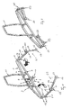
- Vehicle rear carrier a main cross member 1 as a central Component consisting of two spars 2, 3 with a rectangular hollow profile consists of a trapeze in the top view and on their ends are welded together.
- the two spars 2, 3 are in their Middle sections where they have the greatest parallel spacing have each other, by means of struts 4, 5 welded to them stiffened, which connect the spars 2, 3 and thus form a kind of grid construction.
- the spars 2, 3 in the middle of a coupling element 6 known Design welded on.
- the coupling element 6 is only for better understanding with its most important parts shown in Fig. 1.
- the coupling element 6 consists of a toggle lever 7 with handle that has a power transmission mechanism (not shown) with a pivotable on one Coupling element housing 8 held spherical cap or Ball half shell 9 is engaged.
- This swivel Spherical cap 9 is located opposite one fixed to the housing Spherical cap (not shown in Fig. 1), in between the Ball head of a vehicle clutch, not shown to clamp.
- Fig. 1 is also a set screw 10 with Handwheel to see which systematically an adjustment and Folding device represents. This set screw 10 cooperates the coupling neck of the vehicle coupling together to the carrier to the rear and torque into the vehicle clutch initiate.
- a rearward-extending boom stub 12, 13 provided by bending the end portions of the front spar 2 formed around the ends of the rear spar 3 are, these boom stubs 12, 13 through the front the rear spar 3, which is butted and welded on is braced.
- a first bearing bush 14, 15 is welded on, respectively perpendicular to the trapezoid spanned by the main cross member 1 are aligned.
- Hinge bolts are mounted on each of which a first support arm 16, 17 is articulated.
- the first support arms 16, 17 have for this a bearing bush 18, 19 at each of its inner ends, in which the hinge pins are also mounted, such that the bearing bushes 18, 19 of the first support arms 16, 17th below the first bearing bushes 14, 15 of the main cross member 1 arrange and together each a first hinge joint S1 form.
- first support arms 16, 17 are further bearing bushes 20, 21 welded on the front, in which second hinge bolts are mounted.
- second hinge bolts On this second one Hinge bolts are articulated second support arms 22, 23 for this purpose welded to it at its one inner end Bearing bushes 24, 25 have on the second Hinge bolts are attached and therefore second Form hinge joints S2.
- the second support arms 22, 23 are therefore essentially on the same level as the main cross member 1, the first support arms 16, 17 arrange below this level.
- first and second Support arms 16, 17; 22, 23 together with their hinge bushings on each Side of the main cross member 1 each form an articulated linkage G1, G2 or the extendable support structure of the Rear carrier.
- the two linkages G1, G2 from their extended position inwards according to the arrow A indicated in FIG. 1 in the direction are folded or pivoted to the main cross member 1, wherein the first support arms 16, 17 on the first hinges S1 after Swiveled inside and the second support arms 22, 23 in opposite directions the second hinges S2 are pivoted outwards so that the third hinge S3 during this combined movement Maintain the same distance from each other and at the end of the pivoting movement on the first hinges S1 or put on the first support arms 16, 17.
- Fig. 3 shows a panel of the one described above Framework of the vehicle rear carrier according to the invention.
- This cladding consists of a basic segment V1 preferably made of a glass or carbon fiber composite material, the top view of the trapezoidal plan of the Main cross member 1 corresponds and a kind of half-shell or Hood forms, which is placed over the main cross member 1 can be.
- V1 In a central section of the base segment are V1 formed two slot-shaped outbreaks 28 through which the foldable bracket 11 of the main cross member 1 is used can be.
- the end sections of the base segment are V1 also the boom stubs 12, 13 of the main cross member 1 adapted such that the first hinge bushings at the ends 14, 15 are freely accessible to pivot the first To enable support arms 16, 17.
- the cladding provides a second sub-segment V2, which in the top view of the form of a well-known Vehicle bumper is approximated. That is what it is for Sub-segment V2 also made of a plastic composite material, which is shaped into a half-shell or hood. That hood forms an elongated slim middle part 29, the is formed at the end to two tabs 30, 31.
- the length of the Middle part 29 is dimensioned such that the secondary segment V2 can be plugged onto the base segment V1, the two tabs 30, 31 of the secondary segment V2 the first Hinges S1 and boom stubs 12, 13 as well as the base segment Grip V1 on the outside and thus board it.
- a rear side of the secondary segment V2 is in the middle of one Recording 32 for a vehicle registration number including theirs Illumination units 33 and at the end for two rear lights 34, 35 molded.
- Fig. 3rd shown form of the panel is only exemplary. Rather, it is thought of, in particular the secondary segment V2 of the vehicle rear carrier according to the invention in a vehicle-specific manner design, the design idiosyncrasy of each vehicle type is also taken into account with regard to the rear lights 34 and thus an individual carrier design for each vehicle can be created.
- the first and second hinges S1, S2 each have an assembly platform 36, 37 arranged.
- Each platform 36, 37 is thereby one rectangular aluminum or metal plate formed in has a through hole 38, 39 in its center, with which each plate 36, 37 on its hinge pin Hinge S1, S2 is attached.
- the second Mounting platforms 37 are on the hinge pin of the second Hinges S2 are held rotatably and point in a certain Distance to the through hole 39 a hinge in the form of a Bore 40 for the pivotable articulation of a Rotational motion compensation rod 41.
- the rotational movement compensation rod 41 consists of a rod Round full profile that is rectangular at its ends is turned opposite to each other, creating an S-like Form arises. One bent end is in the Bore 40 of the second mounting plate 37 inserted and by means of a locking ring against axial displacement or loosening secured. The other bent end of the Rotational movement compensation rod 41 is rotatable on a lever 42 stored, which is welded to the main cross member 1.
- the Length of the lever 42 or that of the main cross member 1 Fixed articulation point of the rotary motion compensation rod 41 in Lever 42 of each linkage G1, G2 is determined such that when the first support arm 16, 17 is pivoted Rotational movement compensation rod 41 a rotational movement of the second Assembly platform 37 in the opposite direction of rotation, however with respect to substantially the same angular velocity their fulcrum i.e. of the second hinge pin, so that the second mounting platform 37 of each linkage G1, G2 their orientation at every rotational angle position of the first Support arms 16, 17 unchanged.
- the first and second remain Mounting platforms 36, 37 of the linkages G1, G2 in one parallel relative position to each other regardless of the Pivot position of the first support arms 16, 17.
- 5a to 5d is the complete structure of the rear carrier according to the invention and its individual possible Transport positions as a wheel carrier for three wheels in this case shown.
- the secondary cross member 43 has or forms one over the entire Width of the rear carrier third wheel support rail 44, which in the secondary segment V2 and the molded on it Tabs 30, 31 inserted and thus interconnected on three sides is.
- each Linkage rods G1, G2 are also first and second Wheel bearing rails 45, 46 screwed or riveted, the However, length is much shorter than the length of the third Wheel support rail 44, i.e. than the length of the main and Secondary cross member 43, so that between the first Wheel support rails 45, 46, which are connected to the skin cross member 1 are firmly connected at the ends, an intermediate distance along the Main cross member 1 is formed.
- the Lengths of the first and second wheel support rails 45, 46 see above chosen that in the pivoted state of the two Linkage rods G1, G2, the second wheel support rails 46 in Width direction of the rear carrier seen next to the first Wheel support rails 45 in the intermediate distance almost on one Place level and thus the length of the first support rails 45 add the length of the second support rails 46.
- the parallel relative position of the first and second Wheel support rails 45, 46 will be as above described by the rotational movement compensation rods 41 maintained.
- the cantilever of the secondary cross member 43 with respect to the first and second wheel support rails 45, 46 is determined in such a way that the secondary cross member 43 over the first and second Wheel support rails 45, 46 can be moved away.
- the rear carrier is in a Transport position with maximum loading area.
- the bracket 11 is perpendicular to the main cross member 1 opened and locked in this position.
- the Linkage rods G1, G2 are away from the main cross member 1 pivoted, whereby the second wheel support rails 46 in a parallel distance corresponding to the length of the first Support arms 16, 17 in the vehicle longitudinal direction behind the first Place wheel support rails 45.
- the secondary cross member 43 is drawer-shaped along the transverse slots, not shown pulled out the third hinge pin to the rear, so one Distance to the second wheel support rails 46 in To have vehicle longitudinal direction. In this position three Bicycles or the like two-wheelers on the Wheel support rails 45, 46, 44 parked and by means of suitable mounts, for example on the holding bracket 11 be fixed.
- the rear carrier in a first shortened position 5c, for example, for the transport of only two To transfer bicycles, the linkages G1, G2 actuated by the first support arms 16, 17 inwards and the second support arms 22, 23 pivoted in opposite directions to the outside be, the pivoting movements of both linkages G1, G2 is synchronized by the secondary cross member 43.
- the second wheel support rails 46 shift after movement Inside the gap next to the first Wheel support rails 45 and the third wheel support rail 44 behind and above the first and second wheel support rails 45, 46. in this position the cantilever length of the Rear beam of the width of the main and secondary cross beams 1, 43 including the associated formwork and the width of the first or second wheel support rails 45, 46.
- the Secondary cross member 43 along the cross slots at the third Hinge pin in the direction of the main cross member 1 moved like a drawer, the secondary cross member 43 or the third wheel support rail 44 over the first and second Wheel support rails 45, 46 move away until the secondary segment V2 of the panel lies against the main segment V1.
- This Position which is also the most compact position of the Rear carrier represents, embrace the tabs 30, 31 of the Sub-segment V2 the main segment V1 especially in the area the boom stub 12, 13 of the main cross member 1 and the first and second wheel support rails 45, 46, which on the Boom stubs 12, 13 or the first hinge S1 mounted so as to have a substantially closed surface form.
- bracket 11 backwards, i.e. to the rear spar 3 of the main cross member 1 5a folded over and the carrier on its front edge, i.e. upright on the front spar 2 on the floor and sold in a space-saving manner.
- the linkage G1, G2 or their hinges S1, S2 with suitable Locking devices are provided to support arms 16, 17; 22, 23 to fix in the respective angular positions.
- the secondary cross member 43 it is not absolutely necessary, the main and secondary cross members 1, 43 from to build a lattice construction with formwork.
- the formwork itself could be self-supporting Plastic construction or the lattice construction to be replaced by a bending beam.
- the ones running transverse to the secondary cross member 43 can also be used Slots through longitudinal to the secondary cross member 43 Slots to be replaced. In this case the only one would be Movement of the secondary cross member 43 to transfer the Rear carrier from the position shown in FIG. 5c in the position 5b not in the form of a drawer but with a Rotational movement of the second support arms 22, 23 when the first is at rest Support arms 16, 17 coupled.
- the third Hinges S3 inevitably move towards each other, these Movement through the longitudinal slots is made possible.
- the second support arms 22, 23 of the rear carrier according to FIG. 6 and 7 are shortened compared to the first support arms 16, 17, so that when folding or extending the articulated linkage G1, G2 the second support arms together with the outer, third Hinges S3 swung over the second support arms can be, as indicated in Fig. 7.
- mounting platforms 47, 48 are rotatable hinged to which the secondary cross member (not shown) is fixed.
- These mounting brackets 47, 48 have a cross section a U-shaped profile on one of its legs, So upright, are mounted on the third S3 hinges.
- FIGs. 8a and 8b Illustrated embodiment of the invention, wherein hereinafter also only for the first Embodiment different design features is entered into, while all other features are those of the correspond to the first embodiment. It will also be used for the same components used the same reference numerals.
- the support arms 16, 17, 22, 23 are the two Articulated linkage G1, G2 arranged on one level, the Hinges S1, S2 each from a bearing bush 49, 50 exist, which are rotatable in an articulated fork 51, 52 each a hinge pin (not shown) is held.
- the Hinges S1, S2 each from a bearing bush 49, 50 exist, which are rotatable in an articulated fork 51, 52 each a hinge pin (not shown) is held.
- Words are expressed on each boom stub 12, 13 a bearing fork 51 welded on the end face.
- Each support arm 16, 17, 22, 23 has a bearing bush 49, 50 at one end and at the at the other end a storage fork 51, 52. all support arms are identical in this case and can after Modular principle can be directed to each other as desired.
- a third Mounting platform 54 rotatably mounted, the shape and Alignment of the third mounting platform 48 of the second Embodiment corresponds. In this case however third mounting platform 54 further diminished, because all support arms essentially on the same level are located, however, the secondary cross member over the first and second wheel support rails must be movable, as this is based on of the first and second embodiments already described and is shown in principle in FIG. 8b.
- Vehicle rear rack is designed in a modular design. I.e. it can only have first support arms or multiple support arms as required be provided per linkage, so the number of Objects to be transported, for example two-wheelers, or to enlarge the loading area. Nor does it have to be on everyone A mounting platform can be provided for the hinge joint. Much more could in the embodiments described above on the second mounting platforms 36 and thus on the second Wheel support rails 46 are dispensed by the distance between the first support rails 45 and the third To increase support rail 44, for example when transporting Two-wheeled motorcycles.
- the invention relates to a clutch-bound Vehicle rear carrier with an extendable carrier construction, by means of a coupling element to a vehicle coupling is mountable.
- the rear carrier has one for this Main cross member, in the middle section of the coupling element is welded on and at the end portions of each Articulated linkage is arranged, which is the extendable Form support structure.
- Each linkage comprises two hinged support arms, one of which is attached to each arm the main cross member is articulated.
- a mounting platform is arranged, which for attaching a Wheel support rail serves. When collapsed, the regarding the vehicle rear rails between the in Vehicle transverse direction on the outer rails.
Landscapes
- Engineering & Computer Science (AREA)
- Mechanical Engineering (AREA)
- Fittings On The Vehicle Exterior For Carrying Loads, And Devices For Holding Or Mounting Articles (AREA)
- Agricultural Machines (AREA)
Abstract
Description
Es zeigen:
Claims (14)
- Kupplungsgebundener Fahrzeugheckträger mit einer verlängerbaren Trägerkonstruktion, die mittels einem Kupplungselement (6) an eine Fahrzeugkupplung montierbar ist, gekennzeichnet durch
einen Hauptquerträger (1), in dessen Mittelabschnitt das Kupplungselement (6) fixiert ist und an dessen Endabschnitten (12, 13) jeweils ein Gelenkgestänge (G1, G2) angeordnet ist, welche die verlängerbare Trägerkonstruktion bilden. - Fahrzeugheckträger nach Anspruch 1, dadurch gekennzeichnet, daß,
jedes Gelenkgestänge (G1, G2) aus zumindest einem ersten Arm (16, 17) besteht, der an seinem einen, inneren Ende über ein erstes Scharniergelenk (S1) an dem jeweiligen Endabschnitt (12, 13) des Hauptquerträgers (1) angelenkt ist, und dessen Schwenkebene im wesentlichen parallel zum Hauptquerträger (1) liegt. - Fahrzeugheckträger nach Anspruch 2, dadurch gekennzeichnet, daß
jedes Gelenkgestänge (G1, G2) einen zweiten Arm (22, 23) hat, der an seinem einen, inneren Ende an dem freien, äußeren Ende des ersten Arms (16, 17) über ein zweites Scharniergelenk (S2) angeschlossen ist und dessen Schwenkebene parallel zur Schwenkebene des ersten Arms (16, 17) ausgerichtet ist. - Fahrzeugheckträger nach Anspruch 2 oder 3, dadurch gekennzeichnet, daß
an den äußeren Endabschnitten des Hauptquerträgers (12, 13) jeweils eine erste Trägerplattform (36) montiert ist, die sich über eine bestimmte Länge entlang des Hauptquerträgers (1) erstrecken, derart, daß zwischen den ersten Trägerplattformen (36) ein Zwischenabstand entlang des Hauptquerträgers (1) verbleibt. - Fahrzeugheckträger nach Anspruch 4, dadurch gekennzeichnet, daß
an dem jeweils freien Ende jedes ersten Arms (16, 17) eine weitere, zweite Trägerplattform (37) angeordnet ist, derart, daß sie bei einem nach Innen Verschwenken der ersten Arme (16, 17) in Richtung zum Hauptquerträger (1) in dem Zwischenabstand zwischen den ersten Trägerplattformen (36) im wesentlichen auf deren Ebene plazierbar sind. - Fahrzeugheckträger nach Anspruch 5, dadurch gekennzeichnet, daß
die erste und zweite Trägerplattform (36, 37) jedes Gelenkgestänges (G1, G2) als eine Radauflagerschiene oder zur Befestigung einer externen Radauflagerschiene (45, 46) vorgesehen ist, deren Längen derart bestimmt sind, daß die zweiten Radauflagerschienen (46) in nach Innen verschwenkter Position der ersten Arme (16, 17) in den Zwischenabstand der ersten Radauflagerschienen (45) einfügbar sind. - Fahrzeugheckträger nach Anspruch 5 oder 6, dadurch gekennzeichnet, daß
die zweiten Trägerplattformen (37) drehbar an den Enden der ersten Arme (16, 17) vorzugsweise an den zweiten Scharnieren (S2) gelagert sind. - Fahrzeugheckträger nach Anspruch 7, gekennzeichnet durch einen Parallelschwenkmechanismus für die zweite Trägerplattform (37) jedes Gelenkgestänges (G1, G2) bestehend aus einer Drehbewegungsausgleichsstange (41), die an einem Endabschnitt schwenkbar an einem ortsfest am Hauptquerträger fixierten Hebel (42) angelenkt und an ihrem anderen Ende an der jeweils zweiten Trägerplattform (37) schwenkbar angelenkt ist, derart, daß bei einem Verschwenken des jeweils ersten Arms (16, 17) die Drehbewegungsausgleichsstange (41) eine Gegendrehbewegung der zweiten Trägerplattform (37) bewirkt, welche so bemessen ist, daß die zweite Trägerplattform (37) im wesentlichen die gleiche Ausrichtung beibehält.
- Fahrzeugheckträger nach einem der Ansprüche 3 bis 8, dadurch gekennzeichnet, daß
die freien, äußeren Enden der zweiten Arme (22, 23) über einen Nebenquerträger (43) miteinander verbunden sind, der an den freien Enden jedes zweiten Arms (22, 23) über dritte Scharniere (S3) jeweils anscharniert ist. - Fahrzeugheckträger nach Anspruch 9, dadurch gekennzeichnet, daß
der Nebenquerträger (43) eine weitere, dritte Trägerplattform (48, 54) umfaßt, die als Radauflagerschiene (44) ausgebildet oder zur Befestigung einer externen Radauflagerschiene ausgebildet ist. - Fahrzeugheckträger nach Anspruch 10, dadurch gekennzeichnet, daß
die dritte Trägerplattform (44) an den Enden der zweiten Arme (22, 23) derart vorgesehen ist, daß der Nebenquerträger (43) in einer bezüglich der ersten und zweiten Trägerplattformen (36, 37) erhöhten Ebene angeordnet ist, so daß der Nebenquerträger (43) über die ersten und zweiten Trägerplattformen (36, 37) hinweg bewegbar ist. - Fahrzeugheckträger nach Anspruch 11, dadurch gekennzeichnet daß
der Nebenquerträger (43) an seinen Endabschnitten zwei Schlitze hat, in denen jeweils ein Scharnierbolzen des dritten Scharniers (S3) dreh- und längs der Schlitze verschiebbar gehalten ist, wobei jeder Scharnierbolzen mit dem jeweiligen Ende der zweiten Arme (22, 23) verbunden ist. - Fahrzeugheckträger nach Anspruch 12, dadurch gekennzeichnet daß
sich die Schlitze quer zum Nebenquerträger (43) erstrecken, um ein schubladenförmiges Verschieben des Nebenquerträgers (43) an den äußeren freien Enden der zweiten Arme (22, 23) in Richtung zum Hauptquerträger (1) und entgegengesetzt zu ermöglichen. - Fahrzeugheckträger nach Anspruch 12, dadurch gekennzeichnet daß
sich die Schlitze entlang des Nebenquerträgers (43) erstrecken, um ein Verschwenken der zweiten Arme (22, 23) bei ruhenden ersten Armen (16, 17) in Richtung zum Hauptquerträger (1) und entgegengesetzt zu ermöglichen.
Applications Claiming Priority (2)
| Application Number | Priority Date | Filing Date | Title |
|---|---|---|---|
| DE1998156848 DE19856848C2 (de) | 1998-12-09 | 1998-12-09 | Kupplungsgebundener Fahrzeugheckträger |
| DE19856848 | 1998-12-09 |
Publications (3)
| Publication Number | Publication Date |
|---|---|
| EP1008491A2 true EP1008491A2 (de) | 2000-06-14 |
| EP1008491A3 EP1008491A3 (de) | 2001-01-17 |
| EP1008491B1 EP1008491B1 (de) | 2004-03-17 |
Family
ID=7890532
Family Applications (1)
| Application Number | Title | Priority Date | Filing Date |
|---|---|---|---|
| EP19990123708 Expired - Lifetime EP1008491B1 (de) | 1998-12-09 | 1999-11-29 | Kupplungsgebundener Fahrzeugheckträger |
Country Status (2)
| Country | Link |
|---|---|
| EP (1) | EP1008491B1 (de) |
| DE (2) | DE19856848C2 (de) |
Cited By (3)
| Publication number | Priority date | Publication date | Assignee | Title |
|---|---|---|---|---|
| WO2004005075A1 (en) * | 2002-07-08 | 2004-01-15 | Thule Sweden Ab | Load carrier |
| FR2855471A1 (fr) * | 2003-06-02 | 2004-12-03 | Peugeot Citroen Automobiles Sa | Porte-velo pour vehicule automobile |
| US7866517B2 (en) | 2002-10-31 | 2011-01-11 | Fabio Pedrini | Vehicle-mounted equipment carrier |
Families Citing this family (8)
| Publication number | Priority date | Publication date | Assignee | Title |
|---|---|---|---|---|
| DE102008012689A1 (de) * | 2008-03-05 | 2009-09-17 | Westfalia-Automotive Gmbh | Lastenträger |
| DE102009060366B4 (de) * | 2009-12-24 | 2021-07-08 | Volkswagen Ag | Lastenträger |
| DE202014009572U1 (de) | 2014-12-02 | 2016-03-03 | Wilfried Laumann | Verbindungsvorrichtung für einen Heckanbau an einem Fahrzeug |
| DE202014106027U1 (de) | 2014-12-13 | 2015-01-16 | Jens Conrad | Trägerkonstruktion zum Transport von Gegenständen |
| DE102016010007B4 (de) * | 2016-08-13 | 2021-02-25 | Audi Ag | Heckträgersystem für ein Fahrzeug mit einer eine flexible Hecktasche aufnehmenden Tragstruktur sowie Fahrzeug mit einem solchen Heckträgersystem |
| US10759351B2 (en) | 2018-08-07 | 2020-09-01 | Westcott Designs, Inc. | Multipurpose swing arm assembly of a vehicle accessory rack |
| US10661722B2 (en) | 2018-08-07 | 2020-05-26 | Westcott Designs Inc. | Hitch coupling assembly for coupling an accessory to a vehicle |
| USD919549S1 (en) | 2019-03-26 | 2021-05-18 | Westcott Designs, Inc. | Accessory rack for a vehicle |
Citations (1)
| Publication number | Priority date | Publication date | Assignee | Title |
|---|---|---|---|---|
| DE4337006A1 (de) | 1993-10-29 | 1995-05-04 | Paul Bussler | Vorrichtung zum Transport von Lasten an Kraftfahrzeugen |
Family Cites Families (19)
| Publication number | Priority date | Publication date | Assignee | Title |
|---|---|---|---|---|
| FR556603A (de) * | 1923-07-24 | |||
| FR364672A (fr) * | 1905-11-04 | 1906-08-25 | Lucien Joseph Perin | Porte-bagages pour voitures automobiles |
| FR418820A (fr) * | 1910-08-01 | 1910-12-20 | Hussenot Soc | Porte-bagages pour automobiles |
| FR439696A (fr) * | 1912-02-03 | 1912-06-20 | Alfred Driot | Porte-bagages pour automobiles |
| FR439838A (fr) * | 1912-02-07 | 1912-06-24 | Lucien Joseph Perin | Porte-bagages pour véhicules |
| GB120046A (en) * | 1917-10-17 | 1919-07-31 | Henri Paul Richer | Improvements in or relating to Baggage Carriers for Automobiles and other Vehicles. |
| US1585871A (en) * | 1925-02-16 | 1926-05-25 | Edward M Pels | Collapsible luggage carrier for vehicles |
| US1886911A (en) * | 1932-02-24 | 1932-11-08 | Schulman Joseph | Combined collapsible luggage carrier and bumper |
| GB641393A (en) * | 1948-03-09 | 1950-08-09 | Bror Adolf Andersson | Improvements in luggage carriers for automobiles |
| FR59680E (fr) * | 1949-10-29 | 1954-06-29 | Perfectionnements apportés aux porte-bagages pour véhicules | |
| DE8709912U1 (de) * | 1987-07-18 | 1987-09-10 | Eimertenbrink, Helmut, 4971 Hüllhorst | Vorrichtung zum Abstützen von Gegenständen beim Transport durch ein Kraftfahrzeug |
| DE4041085A1 (de) * | 1990-12-21 | 1992-06-25 | Werner Prof Dr Med Buschmann | Kraftfahrzeug mit integrierter transportbuehne |
| DE9218683U1 (de) * | 1992-01-24 | 1995-03-16 | Landgraf, Helmuth, 74372 Sersheim | Heckfahrradträger am PKW auf Anhängerkupplung |
| DE9210885U1 (de) * | 1992-04-03 | 1993-02-25 | Lutz, Alois, 6605 Friedrichsthal | Formschlüssiges und einstellbares Verbindungsteil zum Anschließen von freiauskragenden Gepäckträgern an KFZ-Anhängerkupplungen mit Kugelkopf |
| DE9413008U1 (de) * | 1994-08-11 | 1994-10-06 | c + t comfort technic GmbH, 85521 Ottobrunn | Fahrzeuglastträger |
| DE19538266A1 (de) * | 1995-10-16 | 1997-04-17 | Norbert Hoerl | Integrierter Lastenträger für/an Fahrzeugen |
| DE29600485U1 (de) * | 1996-01-12 | 1997-05-15 | SMV-Metall GmbH, 49163 Bohmte | Tragvorrichtung für einen heckseitigen Anbau an Kraftfahrzeugen |
| DE19624017A1 (de) * | 1996-06-15 | 1997-12-18 | Brutsaert Accessories Nv | Lastträger |
| US5884826A (en) * | 1997-08-05 | 1999-03-23 | Shaver; Tori | Vehicle equipment rack |
-
1998
- 1998-12-09 DE DE1998156848 patent/DE19856848C2/de not_active Expired - Fee Related
-
1999
- 1999-11-29 EP EP19990123708 patent/EP1008491B1/de not_active Expired - Lifetime
- 1999-11-29 DE DE59908869T patent/DE59908869D1/de not_active Expired - Fee Related
Patent Citations (1)
| Publication number | Priority date | Publication date | Assignee | Title |
|---|---|---|---|---|
| DE4337006A1 (de) | 1993-10-29 | 1995-05-04 | Paul Bussler | Vorrichtung zum Transport von Lasten an Kraftfahrzeugen |
Cited By (4)
| Publication number | Priority date | Publication date | Assignee | Title |
|---|---|---|---|---|
| WO2004005075A1 (en) * | 2002-07-08 | 2004-01-15 | Thule Sweden Ab | Load carrier |
| CN100347002C (zh) * | 2002-07-08 | 2007-11-07 | 北部瑞典公司 | 承载器 |
| US7866517B2 (en) | 2002-10-31 | 2011-01-11 | Fabio Pedrini | Vehicle-mounted equipment carrier |
| FR2855471A1 (fr) * | 2003-06-02 | 2004-12-03 | Peugeot Citroen Automobiles Sa | Porte-velo pour vehicule automobile |
Also Published As
| Publication number | Publication date |
|---|---|
| DE59908869D1 (de) | 2004-04-22 |
| EP1008491A3 (de) | 2001-01-17 |
| DE19856848A1 (de) | 2000-06-21 |
| DE19856848C2 (de) | 2001-07-12 |
| EP1008491B1 (de) | 2004-03-17 |
Similar Documents
| Publication | Publication Date | Title |
|---|---|---|
| EP2176117B1 (de) | Faltrad | |
| DE1919405A1 (de) | Klappbares Fahrgestell fuer ein Fahrzeug | |
| EP3030471B1 (de) | Zusammenlegbarer transportwagen | |
| EP2954938A1 (de) | Klappbarer trettroller mit gepäckträger | |
| DE3705187A1 (de) | Golfwagen | |
| DE4011315C2 (de) | Haltevorrichtung für Fahrzeug-Hecklasten | |
| DE69700295T2 (de) | Einkaufswagen | |
| DE202022106844U1 (de) | Multifunktions-Bollerwagen mit Doppelnutzungsoption, der mit einem Fahrrad und manuell gezogen werden kann | |
| EP1008491B1 (de) | Kupplungsgebundener Fahrzeugheckträger | |
| EP3103712A1 (de) | Faltbarer roller | |
| EP1005436B2 (de) | Fahrbare arbeitsmaschine mit teleskopierbaren stützauslegern | |
| DE202012103182U1 (de) | Lastenträger | |
| DE2516513B2 (de) | Handkarren mit anklappbaren raedern, insbesondere golfkoecherwagen | |
| DE4311998C2 (de) | Zusammenlegbarer Fahrradrahmen | |
| DE102018115003B4 (de) | Ständerbaugruppe und ein fahrrad, welches die ständerbaugruppe verwendet | |
| EP2106777B1 (de) | Rollstuhl | |
| EP2123536B1 (de) | Schiebewagengestell für Kinder- und/oder Puppenwagen | |
| WO2022128229A1 (de) | Elektrokleinstfahrzeug | |
| DE202004014531U1 (de) | Zusammenlegbarer dreirädriger Schiebewagen | |
| EP3838710A1 (de) | Wagen zur verwendung als fahrradanhänger oder als handwagen | |
| DE4316366A1 (de) | Fahrrad | |
| EP3571108B1 (de) | Rahmen eines kinderwagens | |
| DE102014222149B4 (de) | Klappfahrrad | |
| DE202016104928U1 (de) | Klapproller | |
| WO1998056640A1 (de) | Skibob |
Legal Events
| Date | Code | Title | Description |
|---|---|---|---|
| PUAI | Public reference made under article 153(3) epc to a published international application that has entered the european phase |
Free format text: ORIGINAL CODE: 0009012 |
|
| AK | Designated contracting states |
Kind code of ref document: A2 Designated state(s): DE ES FR IT SE |
|
| AX | Request for extension of the european patent |
Free format text: AL;LT;LV;MK;RO;SI |
|
| PUAL | Search report despatched |
Free format text: ORIGINAL CODE: 0009013 |
|
| AK | Designated contracting states |
Kind code of ref document: A3 Designated state(s): AT BE CH CY DE DK ES FI FR GB GR IE IT LI LU MC NL PT SE |
|
| AX | Request for extension of the european patent |
Free format text: AL;LT;LV;MK;RO;SI |
|
| 17P | Request for examination filed |
Effective date: 20010717 |
|
| AKX | Designation fees paid |
Free format text: DE ES FR IT SE |
|
| GRAH | Despatch of communication of intention to grant a patent |
Free format text: ORIGINAL CODE: EPIDOS IGRA |
|
| GRAS | Grant fee paid |
Free format text: ORIGINAL CODE: EPIDOSNIGR3 |
|
| GRAA | (expected) grant |
Free format text: ORIGINAL CODE: 0009210 |
|
| AK | Designated contracting states |
Kind code of ref document: B1 Designated state(s): DE ES FR IT SE |
|
| REF | Corresponds to: |
Ref document number: 59908869 Country of ref document: DE Date of ref document: 20040422 Kind code of ref document: P |
|
| PG25 | Lapsed in a contracting state [announced via postgrant information from national office to epo] |
Ref country code: SE Free format text: LAPSE BECAUSE OF FAILURE TO SUBMIT A TRANSLATION OF THE DESCRIPTION OR TO PAY THE FEE WITHIN THE PRESCRIBED TIME-LIMIT Effective date: 20040617 |
|
| PG25 | Lapsed in a contracting state [announced via postgrant information from national office to epo] |
Ref country code: ES Free format text: LAPSE BECAUSE OF FAILURE TO SUBMIT A TRANSLATION OF THE DESCRIPTION OR TO PAY THE FEE WITHIN THE PRESCRIBED TIME-LIMIT Effective date: 20040628 |
|
| ET | Fr: translation filed | ||
| PLBE | No opposition filed within time limit |
Free format text: ORIGINAL CODE: 0009261 |
|
| STAA | Information on the status of an ep patent application or granted ep patent |
Free format text: STATUS: NO OPPOSITION FILED WITHIN TIME LIMIT |
|
| 26N | No opposition filed |
Effective date: 20041220 |
|
| PGFP | Annual fee paid to national office [announced via postgrant information from national office to epo] |
Ref country code: IT Payment date: 20071127 Year of fee payment: 9 |
|
| PGFP | Annual fee paid to national office [announced via postgrant information from national office to epo] |
Ref country code: FR Payment date: 20071120 Year of fee payment: 9 |
|
| PG25 | Lapsed in a contracting state [announced via postgrant information from national office to epo] |
Ref country code: IT Free format text: LAPSE BECAUSE OF NON-PAYMENT OF DUE FEES Effective date: 20081129 |
|
| PGFP | Annual fee paid to national office [announced via postgrant information from national office to epo] |
Ref country code: DE Payment date: 20090528 Year of fee payment: 10 |
|
| REG | Reference to a national code |
Ref country code: FR Ref legal event code: ST Effective date: 20090731 |
|
| PG25 | Lapsed in a contracting state [announced via postgrant information from national office to epo] |
Ref country code: DE Free format text: LAPSE BECAUSE OF NON-PAYMENT OF DUE FEES Effective date: 20100601 |
|
| PG25 | Lapsed in a contracting state [announced via postgrant information from national office to epo] |
Ref country code: FR Free format text: LAPSE BECAUSE OF NON-PAYMENT OF DUE FEES Effective date: 20081130 |