EP1008495B1 - Kraftfahrzeugsitz mit einem in der Rückenlehne angeordneten Seiten-Airbag - Google Patents
Kraftfahrzeugsitz mit einem in der Rückenlehne angeordneten Seiten-Airbag Download PDFInfo
- Publication number
- EP1008495B1 EP1008495B1 EP99121537A EP99121537A EP1008495B1 EP 1008495 B1 EP1008495 B1 EP 1008495B1 EP 99121537 A EP99121537 A EP 99121537A EP 99121537 A EP99121537 A EP 99121537A EP 1008495 B1 EP1008495 B1 EP 1008495B1
- Authority
- EP
- European Patent Office
- Prior art keywords
- shield
- air bag
- airbag
- vehicle seat
- cut
- Prior art date
- Legal status (The legal status is an assumption and is not a legal conclusion. Google has not performed a legal analysis and makes no representation as to the accuracy of the status listed.)
- Expired - Lifetime
Links
- 230000037431 insertion Effects 0.000 claims 1
- 238000003780 insertion Methods 0.000 claims 1
- 210000002414 leg Anatomy 0.000 description 7
- 239000002184 metal Substances 0.000 description 6
- 210000001364 upper extremity Anatomy 0.000 description 4
- 210000000689 upper leg Anatomy 0.000 description 4
- 239000004744 fabric Substances 0.000 description 3
- 238000010276 construction Methods 0.000 description 2
- 238000000034 method Methods 0.000 description 2
- 239000011324 bead Substances 0.000 description 1
- 230000015572 biosynthetic process Effects 0.000 description 1
- 238000002347 injection Methods 0.000 description 1
- 239000007924 injection Substances 0.000 description 1
- 238000009434 installation Methods 0.000 description 1
- 238000003475 lamination Methods 0.000 description 1
- 239000000463 material Substances 0.000 description 1
- 210000001331 nose Anatomy 0.000 description 1
- 210000002105 tongue Anatomy 0.000 description 1
Images


Classifications
-
- B—PERFORMING OPERATIONS; TRANSPORTING
- B60—VEHICLES IN GENERAL
- B60R—VEHICLES, VEHICLE FITTINGS, OR VEHICLE PARTS, NOT OTHERWISE PROVIDED FOR
- B60R21/00—Arrangements or fittings on vehicles for protecting or preventing injuries to occupants or pedestrians in case of accidents or other traffic risks
- B60R21/02—Occupant safety arrangements or fittings, e.g. crash pads
- B60R21/16—Inflatable occupant restraints or confinements designed to inflate upon impact or impending impact, e.g. air bags
- B60R21/20—Arrangements for storing inflatable members in their non-use or deflated condition; Arrangement or mounting of air bag modules or components
- B60R21/207—Arrangements for storing inflatable members in their non-use or deflated condition; Arrangement or mounting of air bag modules or components in vehicle seats
-
- B—PERFORMING OPERATIONS; TRANSPORTING
- B60—VEHICLES IN GENERAL
- B60R—VEHICLES, VEHICLE FITTINGS, OR VEHICLE PARTS, NOT OTHERWISE PROVIDED FOR
- B60R21/00—Arrangements or fittings on vehicles for protecting or preventing injuries to occupants or pedestrians in case of accidents or other traffic risks
- B60R2021/0002—Type of accident
- B60R2021/0006—Lateral collision
Definitions
- the present invention relates to a motor vehicle seat according to the preamble of claim 1.
- Such a seat is known from DE 197 29 472 C1.
- the the front leg, which is adjacent to the bridge plate, is a strip with the panel in the installed position and protrudes to the side.
- Lugs arranged in the plane of one of several sections protrude, formed inner terminal block.
- the inner Terminal strip is opposite a shorter, outer terminal strip.
- the Snap nose When pushing the panel onto the cutout, the Snap noses into corresponding openings in the bridge plate. there at the same time, the outer terminal strip moves to the outside of the bridge plate, so that this between the inner and the outer terminal block is clamped.
- the aperture is open this way on all sides on the neckline or on one side on Bridge plate set.
- the object of the present invention is in a generic Motor vehicle seat the cover for lamination of the Develop airbag exit while maintaining its advantages.
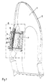
- the backrest shown in Fig. 1 has a back shell 1 made of deep-drawn sheet metal, in the edge area for stiffening circumferential sheet metal profiles 2 are welded.
- the Sheet metal profiles 2 form the load-bearing together with the back shell 1 Structure of the backrest and are subsequently referred to as the backrest frame designated.
- the parts still shown the backrest frame have no meaning for the invention and are therefore not explained further.
- the back frame has in its side area a cutout 3, which according to is closed at the front by a bridge plate 4, which on the Backrest frame welded using 5 hole welds is.
- the bridge plate 4 has a larger plate thickness than that Backrest frame and has profiling and stiffening Beads 6 on. It reinforces the backrest frame in the edge area of section 3.
- the cutout 3 forms an outlet opening for a side airbag housing 7, the structure of which corresponds to the prior art and therefore needs no further explanation.
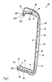
- Fastening points are provided, which are by punch nuts 8 to 11 are formed. Two of these punch nuts 8, 9 are in the sheet metal profile 2 arranged. The other two punch nuts 10, 11 belong to a holding plate 12 which is welded to the back shell 1 (Fig. 7).
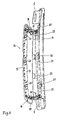
- a screen 13 made of plastic postponed On the edge of the cutout 3 is a screen 13 made of plastic postponed, the construction of which is apparent from FIGS. 3 to 6 and is described below.
- upper leg 14, rear Leg 15 and lower leg 16 of the panel 13 is continuous double-cheeked with an inner cheek 17 and an outer cheek 18, the inner cheeks 17 and the outer cheeks 18 being V-shaped stand apart from each other.
- the outer cheeks 18 are in the gusset and the inner cheeks 17 of the rear leg 15 by triangular Web 19 stiffened against each other.
- locking lugs 20 On the inside the inner cheeks 17 are arranged locking lugs 20, namely three on the rear leg 15 and one each on the upper and lower legs 14 or 16.
- the two guide surfaces 21 are each one by one outside locking latch 22 reinforced.
- These latches 22 have two parallel walls 22.1 and 22.2 through one Web 22.3 are stiffened against each other, i.e. the latches 22 are relatively strong.
- the panel 13 and the airbag housing 7 are assembled as follows:
- the aperture 13 is on the outside of the border of section 3 pushed on and then pressed in. there run the top, back and bottom sheet metal edge of the cutout 3 first on the front slope 20.1 (Fig. 3) of the locking lugs 20 on, whereby the inner cheeks 17 along their entire length Compress inside and then after overriding the catches 20 snap behind them.
- the airbag housing can 7 can be installed. This is done from the inside through the aperture pushed out through it. The inside of the Inner cheeks 17 and their through the retractions at the end of Legs 14 and 16 formed guide surfaces 21 are used as a guide. At the same time, the cover 13 protects the airbag housing 7 from damage, since the sharp sheet metal edges of the Section 3 are covered. Then the airbag housing 7 screwed to the punch nuts 8 to 11. So that is the assembly of the airbag housing 7 completed.
- the cover 13 surrounds the airbag housing 7 with its legs 14, 15 and 16 with only a small game, so that one uniform, small marginal gap results. Furthermore lie the outer cheeks 18 of the panel 13 close to the edge of the cutout 3 and the inner cheeks 17 on the airbag housing 7. Thereby there is a visually appealing connection to the airbag housing 7 or to the backrest frame.
- the airbag housing 7 protrudes in the assembled Condition of a piece from the backrest contour on the side out.
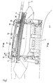
- the bridge plate 4 is with fastening hook 25 for one in Fig. 3 with a Dashed line indicated upholstery fabric 26 of the side pad 24 provided.
- the cover fabric 26 On the inside is the side pad 24 with its cover fabric 26 on the one indicated by a circle 28 Place in a covering 29 of the backrest, which e.g. a Network structure can be clipped on.
- the side pad 24 is thus securely attached, but can be easily by loosening the Interlocking or clipping can be easily removed again.
- the covering 29 in turn is pressed out of the bridge plate 4 Tongues 30 hooked in and on their edge with a Hook wire 31 provided (Fig. 3).
Landscapes
- Engineering & Computer Science (AREA)
- Mechanical Engineering (AREA)
- Air Bags (AREA)
- Seats For Vehicles (AREA)
Description
- Fig. 1
- eine perspektivische Darstellung einer Rükkenlehne ohne Polsterteile mit eingebautem Seiten-Airbag,
- Fig. 2
- eine vergrößerte Darstellung des Ausschnitts A gemäß Fig. 1,
- Fig. 3
- einen Schnitt III-III gemäß Fig. 2 mit eingezeichnetem Seitenpolster,
- Fig. 4
- eine perspektivische Einzeldarstellung der Blende in Einbaulage von innen, schräg vorn und unten gesehen,
- Fig. 5
- eine perspektivische Darstellung gemäß Fig. 4 von schräg hinten und oben gesehen,
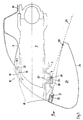
- Fig. 6
- eine perspektivische Darstellung des Brükkenblechs mit eingerasteter Blende etwa in Richtung des Pfeils B gemäß Fig. 3 gesehen, und
- Fig. 7
- eine Darstellung gemäß Fig. 1 bei nicht montiertem Seiten-Airbag.
Claims (1)
- Kraftfahrzeugsitz mit einem in der Rückenlehne angeordneten Seiten-Airbag, wobei der Rückenlehnen-Rahmen in seinem Seitenbereich einen Ausschnitt (3) zum Durchtritt des Seiten-Airbags aufweist, der nach vorn durch ein den Rückenlehnen-Rahmen verstärkendes Brückenblech (4) geschlossen ist, und die Ränder des Ausschnitts (3) durch eine Blende (13) aus Kunststoff eingefaßt sind, deren Schenkel (14-16) zweiwangig mit Innen- (17) und Außenwange (18) ausgeführt sind, wobei die Außenwangen (18) die Ausschnittsränder übergreifen und die Innenwangen (17) in Einschubrichtung des Airbag-Gehäuses (7) nach innen ragen, dadurch gekennzeichnet, daß die Blende (13) eine C-Form besitzt, und in Einbaulage zum Brückenblech (4) hin offen ist, wobei die Enden der oberen und unteren Innenwangen (17) der Blende (13) aufeinander eingebogen sind und so Führungsflächen (21) für das Airbag-Gehäuse (7) bilden, und wobei die Enden der Innenwangen (17) durch jeweils eine Rastnase (22) zum Verrasten der Blende (13) mit dem Brückenblech (4) verstärkt sind.
Applications Claiming Priority (2)
| Application Number | Priority Date | Filing Date | Title |
|---|---|---|---|
| DE19856972A DE19856972C1 (de) | 1998-12-10 | 1998-12-10 | Kraftfahrzeugsitz mit einem in der Rückenlehne angeordneten Seiten-Airbag |
| DE19856972 | 1998-12-10 |
Publications (3)
| Publication Number | Publication Date |
|---|---|
| EP1008495A2 EP1008495A2 (de) | 2000-06-14 |
| EP1008495A3 EP1008495A3 (de) | 2002-02-06 |
| EP1008495B1 true EP1008495B1 (de) | 2003-12-03 |
Family
ID=7890616
Family Applications (1)
| Application Number | Title | Priority Date | Filing Date |
|---|---|---|---|
| EP99121537A Expired - Lifetime EP1008495B1 (de) | 1998-12-10 | 1999-10-29 | Kraftfahrzeugsitz mit einem in der Rückenlehne angeordneten Seiten-Airbag |
Country Status (4)
| Country | Link |
|---|---|
| US (1) | US6234518B1 (de) |
| EP (1) | EP1008495B1 (de) |
| DE (1) | DE19856972C1 (de) |
| ES (1) | ES2212448T3 (de) |
Families Citing this family (35)
| Publication number | Priority date | Publication date | Assignee | Title |
|---|---|---|---|---|
| FR2806679B1 (fr) * | 2000-03-22 | 2002-06-21 | Peugeot Citroen Automobiles Sa | Siege de vehicule automobile comportant un sac gonflable de securite dans une partie laterale de son dossier |
| ATE303921T1 (de) * | 2003-04-02 | 2005-09-15 | Verbesserung in einer oder bezüglich einer an einem sitz befestigten gassackeinheit | |
| US7232001B2 (en) * | 2004-08-24 | 2007-06-19 | Sam Hakki | Collision air bag and flotation system |
| US7328912B2 (en) * | 2004-12-01 | 2008-02-12 | Lear Corporation | Vehicle seat assembly |
| DE102004059277B4 (de) * | 2004-12-09 | 2011-12-29 | Faurecia Autositze Gmbh | Kraftfahrzeugsitz mit Seitenairbag-Modul |
| US9616791B2 (en) * | 2011-05-18 | 2017-04-11 | Toyota Jidosha Kabushiki Kaisha | Seat configuration member and vehicle seat employing the seat configuration member |
| US9376043B2 (en) * | 2011-11-14 | 2016-06-28 | Ford Global Technologies, Llc | Cushion pan for a vehicle seat assembly |
| US8727374B1 (en) * | 2013-01-24 | 2014-05-20 | Ford Global Technologies, Llc | Vehicle seatback with side airbag deployment |
| US9399418B2 (en) | 2013-01-24 | 2016-07-26 | Ford Global Technologies, Llc | Independent cushion extension and thigh support |
| US9409504B2 (en) | 2013-01-24 | 2016-08-09 | Ford Global Technologies, Llc | Flexible seatback system |
| US9415713B2 (en) | 2013-01-24 | 2016-08-16 | Ford Global Technologies, Llc | Flexible seatback system |
| JP6243152B2 (ja) * | 2013-06-27 | 2017-12-06 | テイ・エス テック株式会社 | サイドエアバッグ装置 |
| US9315131B2 (en) | 2014-01-23 | 2016-04-19 | Ford Global Technologies, Llc | Suspension seat back and cushion system having an inner suspension panel |
| US9421894B2 (en) | 2014-04-02 | 2016-08-23 | Ford Global Technologies, Llc | Vehicle seating assembly with manual independent thigh supports |
| US9789790B2 (en) | 2014-10-03 | 2017-10-17 | Ford Global Technologies, Llc | Tuned flexible support member and flexible suspension features for comfort carriers |
| US9566930B2 (en) | 2015-03-02 | 2017-02-14 | Ford Global Technologies, Llc | Vehicle seat assembly with side-impact airbag deployment mechanism |
| US10046682B2 (en) | 2015-08-03 | 2018-08-14 | Ford Global Technologies, Llc | Back cushion module for a vehicle seating assembly |
| US9849817B2 (en) | 2016-03-16 | 2017-12-26 | Ford Global Technologies, Llc | Composite seat structure |
| US10286818B2 (en) | 2016-03-16 | 2019-05-14 | Ford Global Technologies, Llc | Dual suspension seating assembly |
| US9994135B2 (en) | 2016-03-30 | 2018-06-12 | Ford Global Technologies, Llc | Independent cushion thigh support |
| US10220737B2 (en) | 2016-04-01 | 2019-03-05 | Ford Global Technologies, Llc | Kinematic back panel |
| US9889773B2 (en) | 2016-04-04 | 2018-02-13 | Ford Global Technologies, Llc | Anthropomorphic upper seatback |
| US9802512B1 (en) | 2016-04-12 | 2017-10-31 | Ford Global Technologies, Llc | Torsion spring bushing |
| US9845029B1 (en) | 2016-06-06 | 2017-12-19 | Ford Global Technologies, Llc | Passive conformal seat with hybrid air/liquid cells |
| US9834166B1 (en) | 2016-06-07 | 2017-12-05 | Ford Global Technologies, Llc | Side airbag energy management system |
| US9849856B1 (en) | 2016-06-07 | 2017-12-26 | Ford Global Technologies, Llc | Side airbag energy management system |
| US10166895B2 (en) | 2016-06-09 | 2019-01-01 | Ford Global Technologies, Llc | Seatback comfort carrier |
| US10377279B2 (en) | 2016-06-09 | 2019-08-13 | Ford Global Technologies, Llc | Integrated decking arm support feature |
| US10286824B2 (en) | 2016-08-24 | 2019-05-14 | Ford Global Technologies, Llc | Spreader plate load distribution |
| US10279714B2 (en) | 2016-08-26 | 2019-05-07 | Ford Global Technologies, Llc | Seating assembly with climate control features |
| US10239431B2 (en) | 2016-09-02 | 2019-03-26 | Ford Global Technologies, Llc | Cross-tube attachment hook features for modular assembly and support |
| US10391910B2 (en) | 2016-09-02 | 2019-08-27 | Ford Global Technologies, Llc | Modular assembly cross-tube attachment tab designs and functions |
| US9914378B1 (en) | 2016-12-16 | 2018-03-13 | Ford Global Technologies, Llc | Decorative and functional upper seatback closeout assembly |
| US10596936B2 (en) | 2017-05-04 | 2020-03-24 | Ford Global Technologies, Llc | Self-retaining elastic strap for vent blower attachment to a back carrier |
| US10596939B2 (en) | 2017-12-13 | 2020-03-24 | Ford Global Technologies, Llc | Polymeric seat cushion frame integrated module attachment system |
Family Cites Families (6)
| Publication number | Priority date | Publication date | Assignee | Title |
|---|---|---|---|---|
| US5667242A (en) * | 1995-10-17 | 1997-09-16 | Trw Vehicle Safety Systems Inc. | Frame member for a seat mounted vehicle safety apparatus |
| DE19632586B4 (de) * | 1996-08-13 | 2005-02-03 | Adam Opel Ag | Anordnung eines Seiten-Airbag-Moduls an einem Kraftahrzeugsitz |
| US5816660A (en) * | 1997-06-09 | 1998-10-06 | Lear Corporation | Vehicle seat side air bag trim closeout assembly |
| DE19729472C1 (de) * | 1997-07-10 | 1998-11-26 | Faure Bertrand Sitztech Gmbh | Fahrzeugsitz mit einem in der Rückenlehne angeordneten Seiten-Airbag |
| US6089595A (en) * | 1997-12-09 | 2000-07-18 | Autoliv Asp, Inc. | Side impact airbag module |
| US5951039A (en) * | 1998-06-29 | 1999-09-14 | Lear Corp. | Side airbag closeout assembly for vehicular seats and method of installation |
-
1998
- 1998-12-10 DE DE19856972A patent/DE19856972C1/de not_active Expired - Fee Related
-
1999
- 1999-10-29 ES ES99121537T patent/ES2212448T3/es not_active Expired - Lifetime
- 1999-10-29 EP EP99121537A patent/EP1008495B1/de not_active Expired - Lifetime
- 1999-12-10 US US09/457,762 patent/US6234518B1/en not_active Expired - Fee Related
Also Published As
| Publication number | Publication date |
|---|---|
| ES2212448T3 (es) | 2004-07-16 |
| DE19856972C1 (de) | 2000-03-16 |
| EP1008495A2 (de) | 2000-06-14 |
| EP1008495A3 (de) | 2002-02-06 |
| US6234518B1 (en) | 2001-05-22 |
Similar Documents
| Publication | Publication Date | Title |
|---|---|---|
| EP1008495B1 (de) | Kraftfahrzeugsitz mit einem in der Rückenlehne angeordneten Seiten-Airbag | |
| DE60301548T2 (de) | Verbesserung in einer oder bezüglich einer an einem Sitz befestigten Gassackeinheit | |
| DE4229379C2 (de) | Abdeckung für das Gaskissen einer Aufprallschutzvorrichtung für Fahrzeuginsassen | |
| EP0380013B1 (de) | Vorrichtung zur Befestigung eines Dachhimmels einer Schiebedach- oder Schiebehebedachkonstruktion | |
| EP0916534B1 (de) | Rohbautür eines Fahrzeugs | |
| DE102006041734B4 (de) | Vorrichtung zur Befestigung einer Airbageinheit in einer Baugruppe eines Kraftfahrzeugs, insbesondere in einem Lenkrad, durch Verrasten | |
| EP0751727B1 (de) | Zweischalige tragvorrichtung für sitzlehnen-baugruppe | |
| EP2052914B1 (de) | Säulenblende für ein Kraftfahrzeug | |
| DE29822649U1 (de) | Schaumteil aus Polyurethan o.dgl., insbesondere zur Verwendung als Polsterelement bei der Herstellung von Fahrzeugsitzen | |
| DE3707554A1 (de) | Tragschiene fuer einen fahrzeugrahmen und fahrzeugunterbau | |
| DE69204217T2 (de) | Verbesserungen von Luftsack-Aufprall-Schutzsystemen. | |
| EP1384655B1 (de) | Fahrzeugdachmodul | |
| DE10101450A1 (de) | Fahrzeugdach, insbesondere Kraftfahrzeugdach | |
| EP0596306B1 (de) | Abdeckleiste für eine in ein Fahrzeugdach eingelassene Rinne | |
| DE10211734A1 (de) | Verbundbauteil, insbesondere Fahrzeuganbauteil oder Fahrzeugpaneel | |
| DE4446764C2 (de) | Windschott für ein Cabriolet | |
| EP0827880B1 (de) | Anordnung eines Seiten-Airbag-Moduls an einem Kraftfahrzeugsitz | |
| DE10219053A1 (de) | Belüftungseinrichtung | |
| EP1147949B1 (de) | Gassackmodul | |
| DE4330439C2 (de) | Formsteifes Verkleidungsteil für einen Fahrzeugaufbau | |
| DE19729472C1 (de) | Fahrzeugsitz mit einem in der Rückenlehne angeordneten Seiten-Airbag | |
| DE10141461B4 (de) | Anordnung eines Seiten-Airbag-Moduls an einen Kraftfahrzeugsitz | |
| EP0826563B1 (de) | Abdeckung eines in ein Fahrzeuglenkrad integrierten Gassack-Moduls | |
| EP2105065A1 (de) | Möbelkorpus | |
| DE3601891C2 (de) |
Legal Events
| Date | Code | Title | Description |
|---|---|---|---|
| PUAI | Public reference made under article 153(3) epc to a published international application that has entered the european phase |
Free format text: ORIGINAL CODE: 0009012 |
|
| AK | Designated contracting states |
Kind code of ref document: A2 Designated state(s): AT BE CH CY DE DK ES FI FR GB GR IE IT LI LU MC NL PT SE Kind code of ref document: A2 Designated state(s): ES FR GB IT SE |
|
| AX | Request for extension of the european patent |
Free format text: AL;LT;LV;MK;RO;SI |
|
| PUAL | Search report despatched |
Free format text: ORIGINAL CODE: 0009013 |
|
| AK | Designated contracting states |
Kind code of ref document: A3 Designated state(s): AT BE CH CY DE DK ES FI FR GB GR IE IT LI LU MC NL PT SE |
|
| AX | Request for extension of the european patent |
Free format text: AL;LT;LV;MK;RO;SI |
|
| 17P | Request for examination filed |
Effective date: 20020117 |
|
| AKX | Designation fees paid |
Free format text: ES FR GB IT SE |
|
| REG | Reference to a national code |
Ref country code: DE Ref legal event code: 8566 |
|
| GRAH | Despatch of communication of intention to grant a patent |
Free format text: ORIGINAL CODE: EPIDOS IGRA |
|
| RAP1 | Party data changed (applicant data changed or rights of an application transferred) |
Owner name: SMART GMBH |
|
| GRAS | Grant fee paid |
Free format text: ORIGINAL CODE: EPIDOSNIGR3 |
|
| GRAA | (expected) grant |
Free format text: ORIGINAL CODE: 0009210 |
|
| AK | Designated contracting states |
Kind code of ref document: B1 Designated state(s): ES FR GB IT SE |
|
| REG | Reference to a national code |
Ref country code: GB Ref legal event code: FG4D Free format text: NOT ENGLISH |
|
| REG | Reference to a national code |
Ref country code: IE Ref legal event code: FG4D Free format text: GERMAN |
|
| GBT | Gb: translation of ep patent filed (gb section 77(6)(a)/1977) |
Effective date: 20040218 |
|
| REG | Reference to a national code |
Ref country code: SE Ref legal event code: TRGR |
|
| REG | Reference to a national code |
Ref country code: ES Ref legal event code: FG2A Ref document number: 2212448 Country of ref document: ES Kind code of ref document: T3 |
|
| REG | Reference to a national code |
Ref country code: IE Ref legal event code: FD4D |
|
| ET | Fr: translation filed | ||
| PLBE | No opposition filed within time limit |
Free format text: ORIGINAL CODE: 0009261 |
|
| STAA | Information on the status of an ep patent application or granted ep patent |
Free format text: STATUS: NO OPPOSITION FILED WITHIN TIME LIMIT |
|
| PGFP | Annual fee paid to national office [announced via postgrant information from national office to epo] |
Ref country code: SE Payment date: 20041012 Year of fee payment: 6 Ref country code: FR Payment date: 20041012 Year of fee payment: 6 |
|
| PGFP | Annual fee paid to national office [announced via postgrant information from national office to epo] |
Ref country code: GB Payment date: 20041018 Year of fee payment: 6 |
|
| PGFP | Annual fee paid to national office [announced via postgrant information from national office to epo] |
Ref country code: ES Payment date: 20041020 Year of fee payment: 6 |
|
| 26N | No opposition filed |
Effective date: 20040906 |
|
| PG25 | Lapsed in a contracting state [announced via postgrant information from national office to epo] |
Ref country code: IT Free format text: LAPSE BECAUSE OF NON-PAYMENT OF DUE FEES Effective date: 20051029 Ref country code: GB Free format text: LAPSE BECAUSE OF NON-PAYMENT OF DUE FEES Effective date: 20051029 |
|
| PG25 | Lapsed in a contracting state [announced via postgrant information from national office to epo] |
Ref country code: SE Free format text: LAPSE BECAUSE OF NON-PAYMENT OF DUE FEES Effective date: 20051030 |
|
| PG25 | Lapsed in a contracting state [announced via postgrant information from national office to epo] |
Ref country code: ES Free format text: LAPSE BECAUSE OF NON-PAYMENT OF DUE FEES Effective date: 20051031 |
|
| EUG | Se: european patent has lapsed | ||
| GBPC | Gb: european patent ceased through non-payment of renewal fee |
Effective date: 20051029 |
|
| PG25 | Lapsed in a contracting state [announced via postgrant information from national office to epo] |
Ref country code: FR Free format text: LAPSE BECAUSE OF NON-PAYMENT OF DUE FEES Effective date: 20060630 |
|
| REG | Reference to a national code |
Ref country code: FR Ref legal event code: ST Effective date: 20060630 |
|
| REG | Reference to a national code |
Ref country code: ES Ref legal event code: FD2A Effective date: 20051031 |