EP1008515A2 - Aérofrein pour aile d'aéronef - Google Patents
Aérofrein pour aile d'aéronef Download PDFInfo
- Publication number
- EP1008515A2 EP1008515A2 EP99890365A EP99890365A EP1008515A2 EP 1008515 A2 EP1008515 A2 EP 1008515A2 EP 99890365 A EP99890365 A EP 99890365A EP 99890365 A EP99890365 A EP 99890365A EP 1008515 A2 EP1008515 A2 EP 1008515A2
- Authority
- EP
- European Patent Office
- Prior art keywords
- spoiler
- component
- during
- flap
- landing
- Prior art date
- Legal status (The legal status is an assumption and is not a legal conclusion. Google has not performed a legal analysis and makes no representation as to the accuracy of the status listed.)
- Granted
Links
- 239000000463 material Substances 0.000 claims description 6
- 239000002131 composite material Substances 0.000 claims description 5
- 239000000835 fiber Substances 0.000 claims description 5
- 239000000853 adhesive Substances 0.000 claims description 2
- 230000001070 adhesive effect Effects 0.000 claims description 2
- 239000004918 carbon fiber reinforced polymer Substances 0.000 claims description 2
- 230000000694 effects Effects 0.000 description 2
- 229920000049 Carbon (fiber) Polymers 0.000 description 1
- 230000002411 adverse Effects 0.000 description 1
- 238000013459 approach Methods 0.000 description 1
- 239000004760 aramid Substances 0.000 description 1
- 229920006231 aramid fiber Polymers 0.000 description 1
- 239000004917 carbon fiber Substances 0.000 description 1
- 238000010276 construction Methods 0.000 description 1
- 230000006378 damage Effects 0.000 description 1
- 239000004744 fabric Substances 0.000 description 1
- 239000003365 glass fiber Substances 0.000 description 1
- 239000004033 plastic Substances 0.000 description 1
- 229920003023 plastic Polymers 0.000 description 1
- 238000000926 separation method Methods 0.000 description 1
Images



Classifications
-
- B—PERFORMING OPERATIONS; TRANSPORTING
- B64—AIRCRAFT; AVIATION; COSMONAUTICS
- B64C—AEROPLANES; HELICOPTERS
- B64C9/00—Adjustable control surfaces or members, e.g. rudders
- B64C9/32—Air braking surfaces
- B64C9/323—Air braking surfaces associated with wings
-
- B—PERFORMING OPERATIONS; TRANSPORTING
- B64—AIRCRAFT; AVIATION; COSMONAUTICS
- B64C—AEROPLANES; HELICOPTERS
- B64C9/00—Adjustable control surfaces or members, e.g. rudders
- B64C9/32—Air braking surfaces
-
- B—PERFORMING OPERATIONS; TRANSPORTING
- B64—AIRCRAFT; AVIATION; COSMONAUTICS
- B64C—AEROPLANES; HELICOPTERS
- B64C9/00—Adjustable control surfaces or members, e.g. rudders
- B64C9/34—Adjustable control surfaces or members, e.g. rudders collapsing or retracting against or within other surfaces or other members
-
- Y—GENERAL TAGGING OF NEW TECHNOLOGICAL DEVELOPMENTS; GENERAL TAGGING OF CROSS-SECTIONAL TECHNOLOGIES SPANNING OVER SEVERAL SECTIONS OF THE IPC; TECHNICAL SUBJECTS COVERED BY FORMER USPC CROSS-REFERENCE ART COLLECTIONS [XRACs] AND DIGESTS
- Y02—TECHNOLOGIES OR APPLICATIONS FOR MITIGATION OR ADAPTATION AGAINST CLIMATE CHANGE
- Y02T—CLIMATE CHANGE MITIGATION TECHNOLOGIES RELATED TO TRANSPORTATION
- Y02T50/00—Aeronautics or air transport
- Y02T50/40—Weight reduction
Definitions
- the invention relates to a spoiler for wings, in particular of aircraft, which Spoiler can be opened during landing and during takeoff of the aircraft or the like and can be collapsed during the cruise.
- Spoilers are spoilers on the rear upper side of the wings understood, which on the one hand as brake flaps during landing and on the other hand also serve to support the aileron through asymmetrical use.
- the English The term “spoiler” comes from the fact that it creates a resistance and thereby part of the Buoyancy destroyed.
- CH 683 982 A5 describes a device for increasing buoyancy on one Aircraft wing in the form of an air guiding element, which also serves as a spoiler after landing can serve.
- the aim of the present invention is therefore to provide a spoiler, which in particular is suitable for use with particularly large and heavy aircraft, and improved aerodynamic conditions during landing and during takeoff of the aircraft od.
- a spoiler which in particular is suitable for use with particularly large and heavy aircraft, and improved aerodynamic conditions during landing and during takeoff of the aircraft od.
- the aerodynamic conditions during the cruise be adversely affected.
- the spoiler in the higher Speed range during cruise the aerodynamic conditions should negatively affect while in the low speed range during the Landing should have the smallest possible or defined distance to the flap.
- the Disadvantages of known designs should be avoided or at least reduced.
- the spoiler should be characterized by the lowest possible weight.
- the object of the invention is achieved in that the opposite of the direction of flight seen rear edge of the spoiler, a component is arranged, which during the Landing or take-off maneuvers with the flaps extended when the Spoiler between the rear edge of the spoiler and the surface of the flap formed gap is reduced and which with the landing flap retracted and retracted Spoiler lies against the surface of the flap during the cruise.
- a component is arranged, which during the Landing or take-off maneuvers with the flaps extended when the Spoiler between the rear edge of the spoiler and the surface of the flap formed gap is reduced and which with the landing flap retracted and retracted Spoiler lies against the surface of the flap during the cruise.
- the component is made of composite material, in particular made of carbon fiber reinforced plastic.
- This material is through characterized by low weight and high mechanical properties. It is also that Use of plastics with glass fibers or aramid fibers or similar fibers possible, but the carbon fibers have the best mechanical properties demonstrate.
- the component consists of several layers of tissue, unidirectional material or a combination of these with defined fiber orientations in every position according to the Mechanical properties of the component is built, which can be according to the Present invention different properties of the spoiler can be realized.
- the required flexibility, through which the component is during the Cruise hugs the neighboring components and on the other hand the desired one Stiffness that the component is not bent during the landing flight achieved become.
- the cross section of the component advantageously tapers towards the free end educated. This increases the flexibility of the free end and during the Cruise optimal contact of the component on the wing with the least Resistance achieved and also the vibrating masses at the end of the component reduced.
- the free end of the component is towards the surface of the Wing or flap is curved out.
- a bias can have a defined gap during landing and during takeoff of the aircraft between spoiler and flap for optimal aerodynamic conditions become.
- Appropriate flexibility of the component is required, the component during the cruise with a smooth wing against the curvature or bias the flap pressed.
- the component in is arranged substantially over the entire length of the rear edge of the spoiler.
- the component If the component is made up of several parts, it must be damaged of a part of the component, the entire component cannot be replaced.
- the flexibility of the free end of the component can be increased in that the Has component at the free end substantially in the flight direction oriented incisions. These cuts result in an essentially comb-like shape of the component, and the properties of the component can be optimized.
- the component with the Spoiler is detachably connected, for example via riveted or screw connections.
- connection of the component with the spoiler can also be via a Adhesive connection or the like.
- the free end of the component is rounded or counter the direction to the surface of the wing or flap is bent.
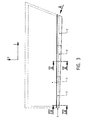
- Fig. 1 shows a wing 1 of an aircraft in a view from above.
- the arrow F shows the Direction of flight on, while arrow 1 indicates the direction of the fuselage (not shown) indicates.
- On the rear upper side of the wing there are several in front of the flaps 5 Spoiler 2, a total of six spoilers 2 arranged in the example shown.
- the spoilers 2 are opened during the landing to destroy the lift.
- the spoilers 2 usually have not only their function as airbrakes Aileron support function.
- a spoiler 2 is with the invention Provided device which consists essentially of a component 3, which on the rear edge 4 of the spoiler 2, which is seen against the direction of flight F.
- the second spoiler 2 seen from the fuselage with the device provided according to the invention, in this spoiler 2, the gap between the rear edge 4 of the spoiler 2 and the flap 5 is largest. But it can also other spoilers 2 or all spoilers 2 can be provided with the component 3. On the one hand, it has to Component 3 be flexible enough so that it can travel at higher speeds no resistance and on the other hand stiff enough that a defined gap to Landing flap 5 can be achieved for an optimal aerodynamic effect.
- the component 3 made of fiber composite materials, so that the one another opposite tasks can be solved satisfactorily. It is also conceivable to produce the component 3 itself from rigid material and via an elastic Connection to connect to the rear edge 4 of the spoiler 2.
- the spoiler 2 shows a spoiler 2 with the component 3 according to the invention in perspective Shown view.
- the spoiler 2 which is usually constructed from composite materials, has in essential wedge shape.
- the component 3 consists of three Parts 3 'built. This has the advantage that if a part 3 'is not damaged must be replaced completely.
- the separation of the parts 3 ' Component 3 flexibility increased. This can also be achieved by making cuts are arranged at the free end of the component 3 essentially in the direction of flight F (not shown).
- Such a comb-like construction serves to optimize the properties the rear edge extension of the spoiler 2.
- FIG. 3 shows a top view of the spoiler 2 according to FIG. 2.
- the component 3 according to the shape of the Wing 1 is the component 3 not with a constant width, but in the direction of Aircraft fuselage (direction of arrow I) made wider.
- the component 3 is in the arranged substantially over the entire length of the spoiler 2.
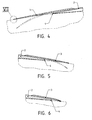
- the component 3 for the case of cruise (solid lines) and for reproduced the landing flight (dashed line).
- the spoiler is in cruise flight 2 folded and the component 3 nestles flat on the surface of the Flap 5 on and increases the overlap of the spoiler 2 with the land flap 5.
- the spoiler 2 is opened and the component 3 is curved in the direction of the wing 1 or flap 5 as shown.
- the rigidity of the component 3 must be chosen so that it approaches the landing or does not vibrate or flutter during the start maneuver.
- the component 3 be so flexible that this with the spoiler 2 folded against the curvature of the Surface of the flap 5 can be pressed.
- FIG. 5 and FIG. 6 show the execution of the Component 3 with a different cross section can be seen.
- the free end of the Component 3 tapering training contributes to a reduction in the vibrating Masses at the end of the component 3 also to a better support on the surface of the Landing flap 5 during the cruise, resulting in a smooth wing 1.
- FIG. 7 shows a special embodiment variant of the invention Component 3, in which the free end is rounded or against the direction of the surface the wing 1 or flap 5 is designed bent. This prevents it after landing when the flaps 5 are retracted to an unauthorized Friction of the component 3 comes on the surface of the flap 5.
- the rounded free end allows smooth sliding on the surface of the flap.
- the properties of the component 3 or the rear end of the spoiler 2 in one piece Execution can be achieved by varying the cross section and properties of the material Requirements are adjusted. Especially when using composite materials can be done by a targeted variation of the fiber orientation of each layer of the fabric or unidirectional material or a combination thereof the task of the invention be solved.
Landscapes
- Engineering & Computer Science (AREA)
- Aviation & Aerospace Engineering (AREA)
- Laminated Bodies (AREA)
- Body Structure For Vehicles (AREA)
- Dowels (AREA)
- Transition And Organic Metals Composition Catalysts For Addition Polymerization (AREA)
- Aiming, Guidance, Guns With A Light Source, Armor, Camouflage, And Targets (AREA)
- Vehicle Step Arrangements And Article Storage (AREA)
- Fittings On The Vehicle Exterior For Carrying Loads, And Devices For Holding Or Mounting Articles (AREA)
Priority Applications (1)
| Application Number | Priority Date | Filing Date | Title |
|---|---|---|---|
| AT99890365T ATE287356T1 (de) | 1998-12-11 | 1999-11-15 | Spoiler für tragflächen |
Applications Claiming Priority (2)
| Application Number | Priority Date | Filing Date | Title |
|---|---|---|---|
| AT207998 | 1998-12-11 | ||
| AT0207998A AT406858B (de) | 1998-12-11 | 1998-12-11 | Spoiler für tragflächen |
Publications (3)
| Publication Number | Publication Date |
|---|---|
| EP1008515A2 true EP1008515A2 (fr) | 2000-06-14 |
| EP1008515A3 EP1008515A3 (fr) | 2002-07-24 |
| EP1008515B1 EP1008515B1 (fr) | 2005-01-19 |
Family
ID=3527314
Family Applications (1)
| Application Number | Title | Priority Date | Filing Date |
|---|---|---|---|
| EP99890365A Expired - Lifetime EP1008515B1 (fr) | 1998-12-11 | 1999-11-15 | Aérofrein pour aile d'aéronef |
Country Status (6)
| Country | Link |
|---|---|
| US (1) | US6299109B1 (fr) |
| EP (1) | EP1008515B1 (fr) |
| AT (2) | AT406858B (fr) |
| CA (1) | CA2290028C (fr) |
| DE (1) | DE59911483D1 (fr) |
| ES (1) | ES2237076T3 (fr) |
Cited By (2)
| Publication number | Priority date | Publication date | Assignee | Title |
|---|---|---|---|---|
| WO2007001735A2 (fr) | 2005-06-21 | 2007-01-04 | The Boeing Company | Systemes de generation de lacet pour vehicule aerospatial et procedes associes |
| WO2010022710A2 (fr) | 2008-08-28 | 2010-03-04 | Eads Deutschland Gmbh | Aérofrein pour aéronefs |
Families Citing this family (7)
| Publication number | Priority date | Publication date | Assignee | Title |
|---|---|---|---|---|
| US9688384B1 (en) * | 2012-09-20 | 2017-06-27 | The Boeing Company | Methods and apparatus to control a gap between movable aircraft wing components |
| US10501166B2 (en) | 2012-09-20 | 2019-12-10 | The Boeing Company | Methods and apparatus to control a gap between movable aircraft wing components |
| EP3301017B1 (fr) * | 2016-09-30 | 2019-08-07 | Airbus Operations GmbH | Système d'entraînement et de guidage d'une surface de commande de bord de fuite |
| RU171463U1 (ru) * | 2016-10-20 | 2017-06-01 | Российская Федерация от имени которой выступает Министерство промышленности и торговли Российской Федерации (Минпромторг России) | Механизация крыла летательного аппарата |
| US10766600B2 (en) * | 2017-07-28 | 2020-09-08 | The Boeing Company | Articulation assemblies for retracting aircraft flap support fairings and related methods |
| GB2600130A (en) * | 2020-10-22 | 2022-04-27 | Airbus Operations Ltd | Flow control device |
| GB2629364A (en) * | 2023-04-25 | 2024-10-30 | Airbus Operations Ltd | Pop-up spoiler |
Citations (1)
| Publication number | Priority date | Publication date | Assignee | Title |
|---|---|---|---|---|
| CH683982A5 (de) | 1990-10-18 | 1994-06-30 | Frantisek Adamec | Vorrichtung zur Erhöhung des Auftriebes an einem Flügel eines Flugzeuges. |
Family Cites Families (5)
| Publication number | Priority date | Publication date | Assignee | Title |
|---|---|---|---|---|
| US4120470A (en) * | 1976-09-28 | 1978-10-17 | The Boeing Company | Efficient trailing edge system for an aircraft wing |
| US4813631A (en) * | 1982-09-13 | 1989-03-21 | The Boeing Company | Laminar flow control airfoil |
| US4712752A (en) * | 1982-12-06 | 1987-12-15 | The Boeing Company | Wing trailing edge air dam |
| DE3530862A1 (de) * | 1985-08-29 | 1987-03-12 | Messerschmitt Boelkow Blohm | Klappenanordnung fuer einen flugzeugtragfluegel |
| US5224670A (en) * | 1991-09-13 | 1993-07-06 | Grumman Aerospace Corporation | Composite focused load control surface |
-
1998
- 1998-12-11 AT AT0207998A patent/AT406858B/de not_active IP Right Cessation
-
1999
- 1999-11-15 DE DE59911483T patent/DE59911483D1/de not_active Expired - Lifetime
- 1999-11-15 EP EP99890365A patent/EP1008515B1/fr not_active Expired - Lifetime
- 1999-11-15 AT AT99890365T patent/ATE287356T1/de active
- 1999-11-15 ES ES99890365T patent/ES2237076T3/es not_active Expired - Lifetime
- 1999-11-16 US US09/441,058 patent/US6299109B1/en not_active Expired - Lifetime
- 1999-11-18 CA CA002290028A patent/CA2290028C/fr not_active Expired - Lifetime
Patent Citations (1)
| Publication number | Priority date | Publication date | Assignee | Title |
|---|---|---|---|---|
| CH683982A5 (de) | 1990-10-18 | 1994-06-30 | Frantisek Adamec | Vorrichtung zur Erhöhung des Auftriebes an einem Flügel eines Flugzeuges. |
Cited By (6)
| Publication number | Priority date | Publication date | Assignee | Title |
|---|---|---|---|---|
| WO2007001735A2 (fr) | 2005-06-21 | 2007-01-04 | The Boeing Company | Systemes de generation de lacet pour vehicule aerospatial et procedes associes |
| WO2007001735A3 (fr) * | 2005-06-21 | 2007-02-22 | Boeing Co | Systemes de generation de lacet pour vehicule aerospatial et procedes associes |
| WO2010022710A2 (fr) | 2008-08-28 | 2010-03-04 | Eads Deutschland Gmbh | Aérofrein pour aéronefs |
| WO2010022710A3 (fr) * | 2008-08-28 | 2010-10-07 | Eads Deutschland Gmbh | Aérofrein pour aéronefs |
| DE102008044677B4 (de) * | 2008-08-28 | 2012-03-22 | Eads Deutschland Gmbh | Luftbremse für Flugzeuge |
| US8640989B2 (en) | 2008-08-28 | 2014-02-04 | Eads Deutschland Gmbh | Speed brake for aircraft |
Also Published As
| Publication number | Publication date |
|---|---|
| ATE287356T1 (de) | 2005-02-15 |
| US6299109B1 (en) | 2001-10-09 |
| ATA207998A (de) | 2000-02-15 |
| EP1008515B1 (fr) | 2005-01-19 |
| DE59911483D1 (de) | 2005-02-24 |
| EP1008515A3 (fr) | 2002-07-24 |
| CA2290028A1 (fr) | 2000-06-11 |
| ES2237076T3 (es) | 2005-07-16 |
| CA2290028C (fr) | 2006-01-10 |
| AT406858B (de) | 2000-10-25 |
Similar Documents
| Publication | Publication Date | Title |
|---|---|---|
| DE102004056537B4 (de) | Anordnung zur Minderung des aerodynamischen Lärms an einem Zusatzflügel eines Flugzeuges | |
| EP0878393B1 (fr) | Dispositif pour influencer l'écoulement d'air autour de l'emplanture d'aile | |
| DE69013243T2 (de) | Landeklappenzusammenbau. | |
| EP2344379B1 (fr) | Bec de bord d'attaque monté sur la surface portante d'un avion | |
| DE2828162C2 (fr) | ||
| DE2451887C3 (de) | Flugzeugtragflügel | |
| DE3114143C2 (fr) | ||
| DE3534268C2 (fr) | ||
| EP1312545A2 (fr) | Profil aérodynamique avec volet actionnable | |
| DE69508640T2 (de) | Laminarströmungsschicht | |
| DE69910521T2 (de) | Verfahren zur Verminderung des Wellenwiderstandes eines Flugzeuges | |
| DE602004003376T2 (de) | Flugzeug mit störklappen lediglich an der oberseite | |
| EP1008515B1 (fr) | Aérofrein pour aile d'aéronef | |
| EP2429895B1 (fr) | Carénage d'un hypersustentateur | |
| DE102017216399A1 (de) | Steuerfläche für ein Luftfahrzeug und Luftfahrzeug mit flexibler Steuerfläche | |
| DE102008022452A1 (de) | Flugzeug mit aktiv steuerbaren Hilfsflügeln | |
| DE102022124533B4 (de) | Tragflügel oder Höhenleitwerk für ein Flugobjekt | |
| DE102021121394A1 (de) | Luftleitvorrichtung für ein Kraftfahrzeug | |
| DE3150595C2 (fr) | ||
| DE1021249B (de) | Einrichtung an Quertriebsflaechen, insbesondere Luftfahrzeugfluegeln | |
| DE102020106918B4 (de) | Kraftfahrzeug mit einer Unterbodenverkleidung | |
| DE2803041A1 (de) | Schwanzloses flugzeug | |
| DE4405152C2 (de) | Bodeneffektfahrzeug | |
| DE69813090T2 (de) | Seitenleitwerkanordnung für Flugzeuge | |
| DE102023108980B3 (de) | Flugzeug |
Legal Events
| Date | Code | Title | Description |
|---|---|---|---|
| PUAI | Public reference made under article 153(3) epc to a published international application that has entered the european phase |
Free format text: ORIGINAL CODE: 0009012 |
|
| AK | Designated contracting states |
Kind code of ref document: A2 Designated state(s): AT BE CH CY DE DK ES FI FR GB GR IE IT LI LU MC NL PT SE |
|
| AX | Request for extension of the european patent |
Free format text: AL;LT;LV;MK;RO;SI |
|
| PUAL | Search report despatched |
Free format text: ORIGINAL CODE: 0009013 |
|
| AK | Designated contracting states |
Kind code of ref document: A3 Designated state(s): AT BE CH CY DE DK ES FI FR GB GR IE IT LI LU MC NL PT SE |
|
| AX | Request for extension of the european patent |
Free format text: AL;LT;LV;MK;RO;SI |
|
| 17P | Request for examination filed |
Effective date: 20030113 |
|
| AKX | Designation fees paid |
Designated state(s): AT DE ES FR GB IT |
|
| 17Q | First examination report despatched |
Effective date: 20030904 |
|
| GRAP | Despatch of communication of intention to grant a patent |
Free format text: ORIGINAL CODE: EPIDOSNIGR1 |
|
| GRAS | Grant fee paid |
Free format text: ORIGINAL CODE: EPIDOSNIGR3 |
|
| GRAA | (expected) grant |
Free format text: ORIGINAL CODE: 0009210 |
|
| AK | Designated contracting states |
Kind code of ref document: B1 Designated state(s): AT DE ES FR GB IT |
|
| REG | Reference to a national code |
Ref country code: GB Ref legal event code: FG4D Free format text: NOT ENGLISH |
|
| REG | Reference to a national code |
Ref country code: IE Ref legal event code: FG4D Free format text: GERMAN |
|
| REF | Corresponds to: |
Ref document number: 59911483 Country of ref document: DE Date of ref document: 20050224 Kind code of ref document: P |
|
| GBT | Gb: translation of ep patent filed (gb section 77(6)(a)/1977) |
Effective date: 20050420 |
|
| REG | Reference to a national code |
Ref country code: ES Ref legal event code: FG2A Ref document number: 2237076 Country of ref document: ES Kind code of ref document: T3 |
|
| PLBE | No opposition filed within time limit |
Free format text: ORIGINAL CODE: 0009261 |
|
| STAA | Information on the status of an ep patent application or granted ep patent |
Free format text: STATUS: NO OPPOSITION FILED WITHIN TIME LIMIT |
|
| 26N | No opposition filed |
Effective date: 20051020 |
|
| ET | Fr: translation filed | ||
| REG | Reference to a national code |
Ref country code: FR Ref legal event code: CD |
|
| REG | Reference to a national code |
Ref country code: FR Ref legal event code: PLFP Year of fee payment: 17 |
|
| REG | Reference to a national code |
Ref country code: FR Ref legal event code: PLFP Year of fee payment: 18 |
|
| REG | Reference to a national code |
Ref country code: FR Ref legal event code: PLFP Year of fee payment: 19 |
|
| REG | Reference to a national code |
Ref country code: FR Ref legal event code: PLFP Year of fee payment: 20 |
|
| PGFP | Annual fee paid to national office [announced via postgrant information from national office to epo] |
Ref country code: AT Payment date: 20181113 Year of fee payment: 20 Ref country code: DE Payment date: 20181129 Year of fee payment: 20 |
|
| PGFP | Annual fee paid to national office [announced via postgrant information from national office to epo] |
Ref country code: ES Payment date: 20181205 Year of fee payment: 20 Ref country code: FR Payment date: 20181031 Year of fee payment: 20 Ref country code: IT Payment date: 20181126 Year of fee payment: 20 Ref country code: GB Payment date: 20181017 Year of fee payment: 20 |
|
| REG | Reference to a national code |
Ref country code: DE Ref legal event code: R071 Ref document number: 59911483 Country of ref document: DE |
|
| REG | Reference to a national code |
Ref country code: GB Ref legal event code: PE20 Expiry date: 20191114 |
|
| REG | Reference to a national code |
Ref country code: AT Ref legal event code: MK07 Ref document number: 287356 Country of ref document: AT Kind code of ref document: T Effective date: 20191115 |
|
| PG25 | Lapsed in a contracting state [announced via postgrant information from national office to epo] |
Ref country code: GB Free format text: LAPSE BECAUSE OF EXPIRATION OF PROTECTION Effective date: 20191114 |
|
| REG | Reference to a national code |
Ref country code: ES Ref legal event code: FD2A Effective date: 20220105 |
|
| PG25 | Lapsed in a contracting state [announced via postgrant information from national office to epo] |
Ref country code: ES Free format text: LAPSE BECAUSE OF EXPIRATION OF PROTECTION Effective date: 20191116 |