EP1008530A1 - Fermeture inviolable et procédé de fabrication associé - Google Patents
Fermeture inviolable et procédé de fabrication associé Download PDFInfo
- Publication number
- EP1008530A1 EP1008530A1 EP99309635A EP99309635A EP1008530A1 EP 1008530 A1 EP1008530 A1 EP 1008530A1 EP 99309635 A EP99309635 A EP 99309635A EP 99309635 A EP99309635 A EP 99309635A EP 1008530 A1 EP1008530 A1 EP 1008530A1
- Authority
- EP
- European Patent Office
- Prior art keywords
- stop flange
- skirt
- closure
- gussets
- set forth
- Prior art date
- Legal status (The legal status is an assumption and is not a legal conclusion. Google has not performed a legal analysis and makes no representation as to the accuracy of the status listed.)
- Granted
Links
- 238000000034 method Methods 0.000 title claims description 9
- 238000004519 manufacturing process Methods 0.000 title description 4
- 239000011324 bead Substances 0.000 claims abstract description 23
- 230000002093 peripheral effect Effects 0.000 claims abstract description 5
- 238000010276 construction Methods 0.000 claims abstract description 4
- 239000002991 molded plastic Substances 0.000 claims abstract description 4
- 230000006835 compression Effects 0.000 claims description 3
- 238000007906 compression Methods 0.000 claims description 3
- 239000007788 liquid Substances 0.000 abstract description 11
- 238000001035 drying Methods 0.000 description 5
- 238000000465 moulding Methods 0.000 description 5
- 239000000463 material Substances 0.000 description 4
- 238000005336 cracking Methods 0.000 description 3
- 230000015572 biosynthetic process Effects 0.000 description 2
- 239000004033 plastic Substances 0.000 description 2
- 229930091051 Arenine Natural products 0.000 description 1
- 230000004323 axial length Effects 0.000 description 1
- 239000011521 glass Substances 0.000 description 1
- 238000011065 in-situ storage Methods 0.000 description 1
- 238000002347 injection Methods 0.000 description 1
- 239000007924 injection Substances 0.000 description 1
- 239000012263 liquid product Substances 0.000 description 1
- 238000007789 sealing Methods 0.000 description 1
- 125000006850 spacer group Chemical group 0.000 description 1
- 230000003313 weakening effect Effects 0.000 description 1
Images


Classifications
-
- B—PERFORMING OPERATIONS; TRANSPORTING
- B65—CONVEYING; PACKING; STORING; HANDLING THIN OR FILAMENTARY MATERIAL
- B65D—CONTAINERS FOR STORAGE OR TRANSPORT OF ARTICLES OR MATERIALS, e.g. BAGS, BARRELS, BOTTLES, BOXES, CANS, CARTONS, CRATES, DRUMS, JARS, TANKS, HOPPERS, FORWARDING CONTAINERS; ACCESSORIES, CLOSURES, OR FITTINGS THEREFOR; PACKAGING ELEMENTS; PACKAGES
- B65D41/00—Caps, e.g. crown caps or crown seals, i.e. members having parts arranged for engagement with the external periphery of a neck or wall defining a pouring opening or discharge aperture; Protective cap-like covers for closure members, e.g. decorative covers of metal foil or paper
- B65D41/32—Caps or cap-like covers with lines of weakness, tearing-strips, tags, or like opening or removal devices, e.g. to facilitate formation of pouring openings
- B65D41/34—Threaded or like caps or cap-like covers provided with tamper elements formed in, or attached to, the closure skirt
- B65D41/3423—Threaded or like caps or cap-like covers provided with tamper elements formed in, or attached to, the closure skirt with flexible tabs, or elements rotated from a non-engaging to an engaging position, formed on the tamper element or in the closure skirt
- B65D41/3428—Threaded or like caps or cap-like covers provided with tamper elements formed in, or attached to, the closure skirt with flexible tabs, or elements rotated from a non-engaging to an engaging position, formed on the tamper element or in the closure skirt the tamper element being integrally connected to the closure by means of bridges
Definitions
- the present invention relates to tamper-indicating closures, to methods of manufacturing such closures, and to a package that includes such a closure on a container.
- a tamper-indicating closure having a band connected to the skirt of the closure by integral frangible bridges.
- the band has a stop element (e.g., a flange or bead) that engages a bead on the container to resist unthreading of the closure, so that removal of the closure ruptures the frangible bridges that connect the band to the closure skirt.
- U.S. Patent Re33,265, assigned to the assignee hereof discloses a tamper-indicating closure of this character, in which the tamper-indicating band is completely severed from the closure skirt and remains with the container upon removal of the closure from the container.
- U.S. Patent 5,295,600 also assigned to the assignee hereof, discloses a tamper-indicating closure in which the tamper-indicating band remains connected to the closure skirt and is removed from the container with the closure.
- Another and related object of the present invention is to provide a closure and method of manufacture that achieve the foregoing objectives while retaining the advantages of the closures disclosed in the above-noted patents in terms of ease of application to the container finish after filling (lower top load and lower temperature) and whole or partial rupture of the tamper-indicating band from the closure skirt to provide the tamper-indicating feature.
- Yet another object of the present invention is to provide a package, which includes a closure and a container, that is particularly well adapted for use in conjunction with wet finish applications as described.
- a tamper-indicating closure of integrally molded plastic construction in accordance with presently preferred embodiments of the invention include a base wall having a peripheral skirt with internal threads for engaging external threads on a container finish.
- a tamper-indicating band is connected to the edge of the skirt by frangible means such as a plurality of circumferentially spaced integral frangible bridges.
- a stop flange extends axially outwardly and radially inwardly from an edge of the band remote from the skirt for inversion and engagement with a bead on the container finish.
- the stop flange has a circumferentially continuous free edge remote from the band disposed in a plane parallel to the base wall.
- a plurality of circumferentially spaced openings are disposed in the stop flange adjacent to the band for drainage of liquid from between the closure skirt and the container finish.
- a plurality of circumferentially spaced gussets are disposed in the stop flange at the free edge of the flange, with each gusset being disposed circumferentially between an adjacent pair of drainage openings.
- the gussets function during inversion of the stop flange, from an axially outward orientation as molded to an axially inward orientation for use, to absorb compressive stresses on the stop flange and thereby isolate portions of the stop flange surrounding the drainage openings from such compressive stresses.
- the gussets also function following inversion of the stop flange to maintain the geometry of the openings and thereby promote liquid drainage during use.
- the inversion relief gussets preferably are on the outer surface of the stop flange (prior to inversion), and are of uniform dimension circumferentially ofthe stop flange. Thickness of the stop flange between the inversion relief gussets increases from the tamper-indicating band to the free edge of the stop flange, while thickness of the stop flange beneath the gussets is uniform. Thus, the gussets increase in depth radially toward the free edge of the stop flange- In a presently preferred embodiment of the invention, the gussets are in the form of pockets disposed in the outer surface of the stop flange (prior to inversion) opening at the free edge of the stop flange.
- the dimension of the gussets radially and axially along the surface of the stop flange is about one-half or less of the overall dimension of the stop flange.
- the gussets comprise channels that extend axially and radially along the surface of the stop flange between the free edge and the band.
- the circumferential dimension of each gusset is less than the circumferential spacing between drain openings, and is on the order of one-third of such circumferential dimension.
- the drain openings in the stop flange may be of rectangular (including square), semi-circular or triangular configuration.
- the drain openings are disposed in the stop flange adjacent to the band, and preferably extend partially radially into the band.
- a plurality ofcircumferentially spaced lugs extend radially inwardly from the closure skirt for opposed radial abutment with the bead on the container finish. The lugs thus space the skirt from the container bead so as to promote drainage of liquid from between the container finish and the closure skirt, and to permit free passage of drying air to the region between the container finish and the closure skirt.
- This aspect of the invention is useful in connection with closures having a stop element either in the form of a flange as in above-noted U.S. Patent Re33,265 or in the form of a bead as illustrated in U.S. Patents 4,322,009 and 4,432,461, both assigned to the assignee hereof.
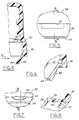
- FIGS. 1-3 illustrate a package 20 in accordance with one presently preferred embodiment of the invention as comprising a container 22 of glass or molded plastic construction and a tamper-indicating closure 24 threaded thereon.
- Container 22 has an axially extending finish 26 for receiving closure 24.
- Closure 24 has a flat base wall 30 on which a sealing liner 32 is secured.
- An annular peripheral skin 34 extends downwardly from closure base wall 30, and has internal threads 36 for securing closure 24 over external threads 28 of container 22.
- a tamper-indicating band 38 is secured to the lower end of skirt 34, being separated therefrom by a circumferential score 40. Tamper-indicating band 38 is thus coupled to closure skirt 34 by a circumferentially spaced array of frangible bridges 41 (FIGS. 2 and 3). Bridges 41 preferably are formed during the scoring operation, as described in the patents referenced hereinafter. Alternatively, the bridges may be molded onto the inside surface of skirt 34 and band 38, as shown in U.S. Patents 4,407,422 and 4,418,828. Alternatively, but less preferably, band 38 may be connected to skirt 34 by a thin frangible web integrally molded with the closure.
- a stop flange 42 extends radially inwardly and axially upwardly (FIG. 2) from the lower end of band 38 to a position beneath a radially outwardly extending bead 44 on container 22 beneath threads 28.
- Bead 44 is sometimes called the container transfer bead or the "A" bead, referring to the fact that bead 44 defines the "A" dimension of the container finish.
- Stop flange 42 preferably thickens radially inwardly from band 38, being thinnest at the integral juncture with band 38 and thickest at the free edge that abuts the container bead.
- Closure 24 may be injection molded as shown or compression molded as taught in U.S. Patent 5,554,327.
- Liner 32 may be separately formed, or more preferably compression molded in situ within a preformed closure as disclosed in U.S. Patents 4,984,703 and 5,451,360.
- U.S. Patents 5,488,888, 5,522,293 and 5,564,319 disclose techniques for forming score 40 and bridges 41 in the scoring operation.
- U.S. Patents 5,755,347 and Re 33,265 disclose techniques for inverting stop flange 42 from the as-molded configuration of FIG. 3 to the configuration of FIG. 2 ready for use. All patents noted herein, assigned to the assignee hereof, are incorporated herein by reference for purposes of background.
- FIGS. 3-8 illustrate closure 24 as molded, before inversion of stop flange 42, formation of score line 40 and molding of liner 32.
- a circumferential array of axially extending lugs 50 are formed on the radially inner surface of skirt 34 during the integral molding operation, and extend radially inwardly from the skirt surface.
- lugs 50 are formed at the conical portion of skin 34 beneath threads 36 and above band 38 at a position such that the lower ends of lugs 50 are not intersected or cut by score line 40.
- lugs 50 effectively form an axial extension of the upper portion of skirt 34, and are disposed for radial abutment with bead 44 on container finish 26 as illustrated in FIG. 2.
- lugs 50 ensure that skirt 34 remains radially spaced from bead 44, while the area between the circumferentially spaced lugs remains free for drainage of liquid from between the closure and finish threads, and for ingress of drying air.
- lugs 50 also cooperate with stop ring 42 when the latter is inverted and pressed against the opposing surface of band 38 to form an abutment surface for back-up tooling during formation of score line 40.
- stop ring 42 when the latter is inverted and pressed against the opposing surface of band 38 to form an abutment surface for back-up tooling during formation of score line 40.
- lugs 50 In a 48 mm closure (standard finish size) in accordance with a presently preferred embodiment of the invention illustrated in FIGS. 1-8, there are twenty-four lugs 50 having centers spaced by 15°, Each lug 50 has a preferred circumferential dimension of 0.060 inches.
- the spacing between diametrically opposed lug surfaces is - 1.889 inches (nominal), as compared with a standard "A" dimension for bead 44 of 48.18 or 48.64 mm.
- the circumferential dimension of lugs 50 is greater than the axial dimension of the lugs.
- a circumferential array of drainage openings 52 are formed in stop flange 42 during the molding operation. Drainage openings 52 are disposed immediately adjacent to tamper-indicating band 38, and preferably extend radially into the inner surface of band 38, as best seen in FIG. 6.
- the opening edge walls in flange 42 and band 38 are axially oriented and parallel to each other due to the axial orientation of the mold tooling that forms the openings. Openings 52 are entirely bounded by flange 42 and band 38. That is, drainage openings 52 do not extend to the free edge 54 of stop flange 42 remote from band 38. Rather, stop flange free edge 54 is circumferentially continuous and disposed in a plane parallel to the plane of closure base wall 30 both prior to inversion (FIGS.
- drain openings 52 are rectangular, having a radial dimension of 0.0452 inches and a circumferential dimension of 0.183 inches. Openings 52 extend 0.022 inches into band 38, which has a lower end thickness of 0.042 inches.
- the total radial and axial length of flange 42, measured from band 38, is 0161 inches.
- the thickness of flange 42 adjacent to band 38 is 0.013 to 0.015 inches, and the thickness at the free edge of the band is 0.035 inches.
- a circumferential array of inversion relief gussets 56 are disposed around the outer surface of stop flange 42. Each gusset 56 is disposed circumferentially midway between an adjacent pair of drainage openings 52.
- the thickness of stop flange 42 between inversion relief gussets 56 increases between band 38 and See edge 54 as previously described. However, as best seen in FIGS. 7 and 8, the thickness of stop flange 42 beneath each gusset 56 is substantially uniform throughout the length and width of the gusset, which is to say that the depth of gusset 56 increases to free edge 54.
- This material flow forms a knit line or area in stop flange 42 beneath each drainage opening 52, which is an area of weakness at which stop flange 42 can fracture during inversion of the stop flange.
- the purpose of gussets 56 is to form weakened areas in the thinner portions of stop flange 42 formed by the gussets, which distort during inversion due to the compressive stresses applied to the stop flange, and thereby isolate such compressive stresses from the areas surrounding the drainage openings, Inversion relief gussets 56 thus help prevent cracking of the stop ring beneath the drainage openings during inversion.
- gussets 56 comprise pockets formed in the outer surface of flange 42 at free edge 54 (i.e., opening into the free edge) and spaced from the band 38.
- Gussets 56 have a circumferential dimensions of 0.060 inches at the base of each gusset, opening outwardly from the base at an angle of 60°.
- each gusset along the surface of the flange is 0.062 inches.
- the circumferential dimension of each gusset (0.060 inches) is thus substantially less than the circumferential dimension between openings 52 (about 0.33 inches). It is preferable that drainage openings 52 occupy as much area as possible without weakening stop flange 42. Inversion relief gussets 56 help prevent cracking at openings 52 as described, and help maintain circularity of stop flange 42 after inversion.
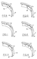
- FIG. 9 illustrates tamper-indicating band 3 8 and stop flange 42 in accordance with the preferred embodiment hereinabove described, including rectangular drain openings 52 and inversion relief gussets 56.
- FIGS. 10-14 illustrate associated modified embodiments of the invention.
- the stop flange 42 includes triangular drainage openings 52 and no inversion relief gussets. It is believed that more uniform material flow can be obtained during the molding operation employing triangular drainage openings 52, so that the knit-line areas of weakness formed at the apex of each opening adjacent to stop flange edge 54 will be less pronounced, and inversion relief gussets are not needed.
- FIG. 10 there were twelve equally spaced drainage openings 52, each having a radial dimension of 0.062 inches (as compared with an overall stop flange radial dimension of 0.156 inches), and side edges at angles of 45° to the radius.
- FIG. 11 illustrates a stop flange 42 having rectangular drainage opening 52 but no inversion relief gussets.
- FIG. 12 illustrates a stop flange 42 having semi-circular drainage openings 52, each with a straight or diametric dimension oriented circumferentially of the stop flange and a semi-circular edge extending into the stop flange.
- An inversion relief gusset 56 is positioned between each adjacent pair of semi-circular drainage openings 52.
- FIG. 13 illustrates an embodiment in which stop flange 42 has square drainage openings 52 and no inversion relief gussets.
- FIG. 14 illustrates an embodiment in which the stop flange 42 includes semi-circular drainage openings 52, again with no inversion relief gussets. It is believed that plastic material will flow more evenly and uniformly around the semi-circular edges of the mold plugs that form openings 52, reducing or eliminating the knit-line weakness between each drainage opening and the free edge 54 of the stop flange, so that inversion relief gussets 56 may not be required to prevent cracking of the stop flange beneath the drainage openings in these embodiments.
- FIGS. 15, 15A and 15B illustrate a modified closure 24 in accordance with the present invention.
- Closure 24 is basically the same as the closure described above, with the exception that drainage slots 60 are provided on the inside diameter of skirt 34, and the inversion relief gussets are in the form of channels 56.
- Each slot 60 is of rectangular geometry, having a long dimension extending axially along the inside surface of the skirt through the container threads.
- the radial or depth dimension of slots 60 is greater than the thickness of threads 36, so that each drainage slot 60 extends radially into the body of skirt 34.
- slots 60 The purpose of slots 60 is to promote drainage of liquid past the container and closure threads to a position within band 38 adjacent to stop flange 42, from which the liquid drains through openings 52. Slots 60 also promote circulation of drying air in the region of the container and closure threads between the container finish and the closure skirt. In an exemplary, 48 mm embodiment, there are nine equally spaced slots 60, each having a circumferential dimension of 0.125 inches. The radial dimension of the slots is 0.010 inches greater than the radius of the inside wall or "T" wall of the closure. Gusset slots 56 extend axially and radially along the surface of flange 42f from band 38 to the free edge of the band.
- FIGS. 16 and 16A illustrate a closure 24 that is basically the same as closure in FIGS. 1-8, except that lugs 50 are axially elongated so as to function not only as spacer lugs with respect to container bead 44, but also as the frangible bridges that couple band 38 to skirt 34. That is, lugs 50 are integrally molded on the inside surface of skirt 34 and band 38 as in prior embodiments, and are of elongated axial dimension as compared with prior embodiments so as to extend through the plane of score line 40. In this way, when the skirt is scored to form score line 40, which separates skirt 34 from band 38, the score intersects but does not fully penetrate lugs 50. Lugs 50 thus serve as the frangible bridges that connect skirt 34 to band 38, and a two-stage scoring operation is not required.
Landscapes
- Engineering & Computer Science (AREA)
- Mechanical Engineering (AREA)
- Closures For Containers (AREA)
- Details Of Rigid Or Semi-Rigid Containers (AREA)
Applications Claiming Priority (2)
| Application Number | Priority Date | Filing Date | Title |
|---|---|---|---|
| US206214 | 1998-12-07 | ||
| US09/206,214 US6119883A (en) | 1998-12-07 | 1998-12-07 | Tamper-indicating closure and method of manufacture |
Publications (2)
| Publication Number | Publication Date |
|---|---|
| EP1008530A1 true EP1008530A1 (fr) | 2000-06-14 |
| EP1008530B1 EP1008530B1 (fr) | 2007-04-25 |
Family
ID=22765440
Family Applications (1)
| Application Number | Title | Priority Date | Filing Date |
|---|---|---|---|
| EP99309635A Expired - Lifetime EP1008530B1 (fr) | 1998-12-07 | 1999-12-01 | Fermeture inviolable et procédé de fabrication associé |
Country Status (9)
| Country | Link |
|---|---|
| US (1) | US6119883A (fr) |
| EP (1) | EP1008530B1 (fr) |
| JP (1) | JP2000168810A (fr) |
| CN (1) | CN1258625A (fr) |
| AU (1) | AU757519B2 (fr) |
| BR (1) | BR9907401B1 (fr) |
| CA (1) | CA2291413C (fr) |
| DE (1) | DE69935897T2 (fr) |
| ZA (1) | ZA997500B (fr) |
Cited By (4)
| Publication number | Priority date | Publication date | Assignee | Title |
|---|---|---|---|---|
| WO2002014170A1 (fr) * | 2000-08-14 | 2002-02-21 | Oeztuerk Guenay | Couvercle a bande de scellement |
| EP1055609A3 (fr) * | 1999-05-17 | 2002-08-28 | Owens-Illinois Closure Inc., | Fermeture inviolable et procédé de fabrication associé |
| DE102010039036A1 (de) * | 2010-08-06 | 2012-02-09 | Bericap Gmbh & Co. Kg | Schraubverschluss mit Flexband |
| US20130248479A1 (en) * | 2011-08-03 | 2013-09-26 | Obrist Closures Switzerland Gmbh | Container Closures |
Families Citing this family (38)
| Publication number | Priority date | Publication date | Assignee | Title |
|---|---|---|---|---|
| US6766916B2 (en) * | 1997-08-01 | 2004-07-27 | Portola Packaging, Inc. | Tamper evidencing closure |
| US6382443B1 (en) * | 1999-04-28 | 2002-05-07 | Owens-Illinois Closure Inc. | Tamper-indicating closure with lugs on a stop flange for spacing the flange from the finish of a container |
| US6659297B2 (en) | 2001-11-28 | 2003-12-09 | Owens-Illinois Closure Inc. | Tamper-indicating closure, container, package and methods of manufacture |
| US7168581B2 (en) | 2001-12-21 | 2007-01-30 | Rexam Medical Packaging Inc. | Closure for a retort processed container having a peelable seal |
| US6877624B2 (en) * | 2002-01-02 | 2005-04-12 | Erie County Plastics | Method of injection molding closure with continuous internal rigid rib, closure made thereby having a lead-in structure and mold for forming same |
| US6974046B2 (en) * | 2002-02-14 | 2005-12-13 | Crown Cork & Seal Technologies Corporation | Tamper evident closure with integrated venting and method of manufacturing |
| US20040011760A1 (en) * | 2002-07-20 | 2004-01-22 | Marco Schupp | Bottle with special top for use in the medical field |
| US6988642B2 (en) * | 2002-10-29 | 2006-01-24 | Johnson & Johnson Consumer Companies | Tamper-evident dispenser bottle |
| US7644902B1 (en) | 2003-05-31 | 2010-01-12 | Rexam Medical Packaging Inc. | Apparatus for producing a retort thermal processed container with a peelable seal |
| US7413097B1 (en) | 2003-08-01 | 2008-08-19 | Portola Packaging, Inc. | Tamper-evident closure and method of making same |
| US7198170B2 (en) * | 2004-01-07 | 2007-04-03 | Berry Plastics Corporation | Closure and container system and method for sealing a closure on a container |
| AU2005265068A1 (en) * | 2004-06-18 | 2006-01-26 | Silgan Closures, Llc | Composite closure with barrier end panel |
| US7798359B1 (en) | 2004-08-17 | 2010-09-21 | Momar Industries LLC | Heat-sealed, peelable lidding membrane for retort packaging |
| US7780024B1 (en) | 2005-07-14 | 2010-08-24 | Rexam Closures And Containers Inc. | Self peel flick-it seal for an opening in a container neck |
| US8100277B1 (en) | 2005-07-14 | 2012-01-24 | Rexam Closures And Containers Inc. | Peelable seal for an opening in a container neck |
| MX2008008306A (es) | 2005-12-28 | 2008-10-17 | Silgan White Cap Americas Llc | Envase esterilizable, con tapa cierre de plastico. |
| GB0620483D0 (en) * | 2006-10-17 | 2006-11-22 | Martin Peter J | The re:tie |
| GB0622398D0 (en) * | 2006-11-09 | 2006-12-20 | Carbonite Corp | Beverage containers |
| DE102007041365B4 (de) * | 2007-08-30 | 2014-07-17 | Bericap Gmbh & Co. Kg | Schraubverschluß mit Garantieband |
| US8251236B1 (en) | 2007-11-02 | 2012-08-28 | Berry Plastics Corporation | Closure with lifting mechanism |
| USD632958S1 (en) * | 2010-06-22 | 2011-02-22 | Rexam Closure Systems Inc. | Closure shell |
| IT1403710B1 (it) * | 2010-12-21 | 2013-10-31 | Sacmi | Tappo a vite |
| IT1403338B1 (it) * | 2010-12-21 | 2013-10-17 | Sacmi | Tappo a vite |
| USD727730S1 (en) | 2012-03-23 | 2015-04-28 | S.C. Johnson & Son, Inc. | Cap |
| USD736634S1 (en) | 2012-03-23 | 2015-08-18 | S.C. Johnson & Son, Inc. | Container with cap |
| WO2014145569A1 (fr) * | 2013-03-15 | 2014-09-18 | Berry Plastics Corporation | Fermeture de récipient |
| USD747201S1 (en) | 2013-09-18 | 2016-01-12 | Bericap | Closure |
| USD723919S1 (en) | 2013-10-24 | 2015-03-10 | Silgan White Cap LLC | Closure |
| FR3015442B1 (fr) | 2013-12-24 | 2016-02-05 | Bericap | Dispositif de bouchage articule avec indicateur de premiere ouverture |
| USD833278S1 (en) | 2014-09-03 | 2018-11-13 | Bericap | Closure for a container |
| CN104443713A (zh) * | 2014-12-17 | 2015-03-25 | 李红彪 | 一种可回盖薄盖饮料瓶 |
| EP3257771A4 (fr) * | 2015-03-30 | 2018-03-14 | Toppan Printing Co., Ltd. | Bouchon de bec verseur et récipient d'emballage |
| GB201601789D0 (en) * | 2016-02-01 | 2016-03-16 | Obrist Closures Switzerland | Improvements in or relating to tamper-evident closures |
| CA3049122A1 (fr) | 2017-01-04 | 2018-07-12 | Berry Plastics Corporation | Bouchon |
| HUP1900085A1 (hu) | 2019-03-21 | 2020-09-28 | Szabolcs Takacs | Lebegõ platform ûrrakéta magasból történõ indítására, valamint eljárás merevfalú ballon világûrbe juttatására |
| MX2022005115A (es) * | 2019-11-15 | 2022-05-30 | Novembal Usa Inc | Tapon que tiene banda de seguridad. |
| CH716855A2 (de) * | 2019-11-20 | 2021-05-31 | Alpla Werke Alwin Lehner Gmbh & Co Kg | Behälterverschluss. |
| US12606351B2 (en) | 2019-12-12 | 2026-04-21 | Plastipak Packaging, Inc. | Tethered closure and container assembly |
Citations (17)
| Publication number | Priority date | Publication date | Assignee | Title |
|---|---|---|---|---|
| US33265A (en) | 1861-09-10 | Improvement in guard-fingers for harvesters | ||
| US4322009A (en) | 1980-05-19 | 1982-03-30 | Owens-Illinois, Inc. | Tamper proof molded plastic closure |
| US4407422A (en) | 1981-06-04 | 1983-10-04 | H-C Industries, Inc. | Composite closure |
| US4418828A (en) | 1981-07-24 | 1983-12-06 | H-C Industries, Inc. | Plastic closure with mechanical pilfer band |
| US4432461A (en) | 1982-04-09 | 1984-02-21 | Owens-Illinois, Inc. | Tamper indicating package |
| US4470513A (en) * | 1982-09-23 | 1984-09-11 | Ethyl Molded Products Company | Tamper-indicating closure |
| US4478343A (en) * | 1982-09-23 | 1984-10-23 | Ethyl Molded Products Company | Tamper-indicating closure |
| US4984703A (en) | 1989-10-03 | 1991-01-15 | Owens-Illinois Closure Inc. | Plastic closure with compression molded sealing liner |
| US5295600A (en) | 1993-02-25 | 1994-03-22 | Owens-Illinois Closure Inc. | Tamper indicating closure |
| US5451360A (en) | 1993-10-14 | 1995-09-19 | Owens-Illinois Closure Inc. | Method and apparatus for compression molding closure liners |
| US5488888A (en) | 1993-04-19 | 1996-02-06 | Owens-Illinois Closure Inc. | Method of forming bridges in tamper indicating closures |
| US5522293A (en) | 1993-10-14 | 1996-06-04 | Owens-Illinois Closure Inc. | Method and apparatus for accurately positioning a knife blade for scoring plastic tamper indicating closures |
| US5554327A (en) | 1993-10-14 | 1996-09-10 | Owens-Illinois Closure Inc. | Method and apparatus for compression molding plastic articles |
| WO1996027532A1 (fr) * | 1995-03-06 | 1996-09-12 | White Cap, Inc. | Fermeture composite et son procede de production |
| EP0801005A1 (fr) * | 1995-11-15 | 1997-10-15 | Shibazaki Seisakusho Ltd. | Dispositif de fermeture et recipient |
| US5727705A (en) * | 1996-11-22 | 1998-03-17 | Crown Cork & Seal Technologies Corporation | Closure cap for closure of a container mouth |
| US5755347A (en) | 1989-07-27 | 1998-05-26 | Owens-Illinois Closure Inc. | Tamper indicating package |
Family Cites Families (50)
| Publication number | Priority date | Publication date | Assignee | Title |
|---|---|---|---|---|
| US3297184A (en) * | 1963-11-05 | 1967-01-10 | B D Lab Inc | Cap for culture tubes |
| US3374913A (en) * | 1965-10-08 | 1968-03-26 | Continental Can Co | Tamper-proof package |
| US3329295A (en) * | 1965-11-29 | 1967-07-04 | Zbislaw M Roehr | Tamper-indicating closure |
| US3438528A (en) * | 1967-08-04 | 1969-04-15 | Roehr Metals & Plastics Co | Tamper-indicating closure |
| US3484012A (en) * | 1968-01-22 | 1969-12-16 | Continental Can Co | Tamper-proof package |
| US3861551A (en) * | 1971-02-22 | 1975-01-21 | Charles N Hannon | Threaded bottle cap with vertical external scores |
| US3784041A (en) * | 1971-05-05 | 1974-01-08 | R Birch | Closure cap |
| DE2213773A1 (de) * | 1972-03-22 | 1973-09-27 | Vinzenz Boehm | Telefonnummernverzeichnis |
| US3858743A (en) * | 1973-10-15 | 1975-01-07 | Owens Illinois Inc | Tamperproof package |
| FR2291915A2 (fr) * | 1974-11-19 | 1976-06-18 | Astra Plastique | Perfectionnements aux dispositifs d'obturation du type inviolable |
| DE2530699A1 (de) * | 1975-07-10 | 1977-01-20 | Zeller Plastik Koehn Graebner | Originalitaetsverschluss fuer behaeltermuendungen |
| US4147268A (en) * | 1976-09-24 | 1979-04-03 | Patel Chandrakant S | Pilfer-proof closure for containers |
| DE7714894U1 (de) * | 1977-05-11 | 1977-08-25 | Behringwerke Ag | Steril verschliessbarer Behaelter |
| AU516094B2 (en) * | 1977-12-14 | 1981-05-14 | Metal Closures Group Limited | Closures for containers |
| US4291813A (en) * | 1978-02-17 | 1981-09-29 | Buckeye Molding Company | Containers and closures |
| FR2421812A1 (fr) * | 1978-04-04 | 1979-11-02 | Alca Sa | Bouchon a vis inviolable en une seule piece moulee en matiere thermoplastique |
| NL7810527A (nl) * | 1978-10-20 | 1980-04-22 | Leer Koninklijke Emballage | Schroefkap met borgrand. |
| US4206851A (en) * | 1979-02-23 | 1980-06-10 | Ethyl Products Company | Tamperproof closure |
| FR2454977A1 (fr) * | 1979-04-27 | 1980-11-21 | Astra Plastique | Perfectionnements aux capsules de bouchage a bague de garantie |
| DE3025751A1 (de) * | 1980-07-08 | 1982-02-04 | Alcoa Deutschland Gmbh Verpackungswerke, 6520 Worms | Schraubverschluss aus kunststoff fuer behaelter mit gewindehals |
| DE3038453A1 (de) * | 1980-10-11 | 1982-05-27 | Stella KG Werner Deussen, 6228 Eltville | Schraubverschluss mit originalitaetssicherung |
| FR2499519A1 (fr) * | 1981-02-11 | 1982-08-13 | Grussen Jean | Capsule de bouchage a vis avec anneau d'inviolabilite |
| US4401227A (en) * | 1981-08-17 | 1983-08-30 | Pehr Harold T | Tamper indicating closure cap |
| US4458821A (en) * | 1982-12-09 | 1984-07-10 | Ethyl Molded Products Company | Tamper-indicating closure |
| US4458822A (en) * | 1982-12-09 | 1984-07-10 | Ethyl Molded Products Company | Tamper-indicating closure |
| US4506795A (en) * | 1983-02-18 | 1985-03-26 | Kerr Glass Manufacturing Corporation | Tamper-evident closure |
| US4576298A (en) * | 1984-05-08 | 1986-03-18 | Continental White Cap, Inc. | Tamper indicating fitment |
| JPS61244757A (ja) * | 1985-04-10 | 1986-10-31 | 喜多産業株式会社 | 合成樹脂製キヤツプ |
| US4613052A (en) | 1985-04-29 | 1986-09-23 | Owens-Illinois, Inc. | Tamper-indicating closure, container and combination thereof |
| JPS62146162A (ja) * | 1985-12-12 | 1987-06-30 | ツエラー プラスティーク ケーン,グレプナー ウント ユー | 原封止装置 |
| US4801031A (en) * | 1987-05-28 | 1989-01-31 | Owens-Illinois Closure Inc. | Tamper-indicating closures and packages |
| JPH01107557A (ja) * | 1987-10-21 | 1989-04-25 | Agency Of Ind Science & Technol | 配線の形成方法 |
| US4895266A (en) * | 1988-11-23 | 1990-01-23 | Continental White Cap, Inc. | Tamper indicating band for plastic closure |
| US4875594A (en) * | 1988-12-16 | 1989-10-24 | Anchor Hocking Corporation | Closure cap |
| US4978016A (en) * | 1989-09-01 | 1990-12-18 | Anchor Hocking Corporation | Tamper indicating closure having retaining hoop with relief windows |
| US5058755A (en) * | 1989-09-01 | 1991-10-22 | Anchor Hocking Packaging Company | Tamper indicating closure having retaining hoop with relief windows |
| US5007545A (en) * | 1990-03-15 | 1991-04-16 | Seaquist Closures | Removal resistant member |
| US4981230A (en) * | 1990-03-15 | 1991-01-01 | Continental White Cap, Inc. | Composite cap including tamper indicating band |
| US5472106A (en) * | 1991-11-08 | 1995-12-05 | Pano Cap (Canada) Limited | Tamper resistant closure cap and a method of operation therefor |
| US5265747A (en) * | 1992-07-28 | 1993-11-30 | Owens-Illinois Closure Inc. | Plastic beverage closure |
| CA2101196C (fr) * | 1992-07-28 | 2005-06-14 | James L. Gregory | Fermeture de contenant a boisson en plastique |
| US5282540A (en) * | 1992-11-23 | 1994-02-01 | Creative Packaging Corp. | Tamper band with flexible engagement member |
| US5400913A (en) * | 1992-12-23 | 1995-03-28 | Crown Cork & Seal Company | Tamper-indicating closure |
| FR2718714B1 (fr) * | 1994-04-15 | 1996-07-19 | Rical Sa | Capsule à vis pour le bouchage du goulot d'un récipient. |
| TW338413U (en) * | 1994-05-17 | 1998-08-11 | Mikasa Industry Co Ltd | Closing device of a container |
| US5775527A (en) * | 1995-02-10 | 1998-07-07 | Crown Cork Ag | Closure cap with anti-tamper strip |
| US5725115A (en) * | 1995-02-21 | 1998-03-10 | Crown Cork Ag | Closure cap with tether |
| JP3825078B2 (ja) * | 1996-02-29 | 2006-09-20 | 日本クラウンコルク株式会社 | タンパーエビデント特性を有する合成樹脂製容器蓋 |
| JPH10119999A (ja) * | 1996-10-18 | 1998-05-12 | Tenryu Kagaku Kogyo Kk | ピルファープルーフキャップ |
| US5947311A (en) * | 1997-05-06 | 1999-09-07 | Owens-Illinois Closure Inc. | Plastic closure with liner having a periphery spaced from the skirt of the closure and a sealing surface angled axially with respect to the base wall of the closure |
-
1998
- 1998-12-07 US US09/206,214 patent/US6119883A/en not_active Expired - Lifetime
-
1999
- 1999-12-01 DE DE69935897T patent/DE69935897T2/de not_active Expired - Lifetime
- 1999-12-01 EP EP99309635A patent/EP1008530B1/fr not_active Expired - Lifetime
- 1999-12-02 CA CA002291413A patent/CA2291413C/fr not_active Expired - Lifetime
- 1999-12-03 AU AU63078/99A patent/AU757519B2/en not_active Ceased
- 1999-12-06 ZA ZA9907500A patent/ZA997500B/xx unknown
- 1999-12-06 CN CN99127762A patent/CN1258625A/zh active Pending
- 1999-12-07 JP JP11347717A patent/JP2000168810A/ja active Pending
- 1999-12-07 BR BRPI9907401-0A patent/BR9907401B1/pt not_active IP Right Cessation
Patent Citations (18)
| Publication number | Priority date | Publication date | Assignee | Title |
|---|---|---|---|---|
| US33265A (en) | 1861-09-10 | Improvement in guard-fingers for harvesters | ||
| US4322009A (en) | 1980-05-19 | 1982-03-30 | Owens-Illinois, Inc. | Tamper proof molded plastic closure |
| US4407422A (en) | 1981-06-04 | 1983-10-04 | H-C Industries, Inc. | Composite closure |
| US4418828A (en) | 1981-07-24 | 1983-12-06 | H-C Industries, Inc. | Plastic closure with mechanical pilfer band |
| US4432461A (en) | 1982-04-09 | 1984-02-21 | Owens-Illinois, Inc. | Tamper indicating package |
| US4470513A (en) * | 1982-09-23 | 1984-09-11 | Ethyl Molded Products Company | Tamper-indicating closure |
| US4478343A (en) * | 1982-09-23 | 1984-10-23 | Ethyl Molded Products Company | Tamper-indicating closure |
| US5755347A (en) | 1989-07-27 | 1998-05-26 | Owens-Illinois Closure Inc. | Tamper indicating package |
| US4984703A (en) | 1989-10-03 | 1991-01-15 | Owens-Illinois Closure Inc. | Plastic closure with compression molded sealing liner |
| US5295600A (en) | 1993-02-25 | 1994-03-22 | Owens-Illinois Closure Inc. | Tamper indicating closure |
| US5488888A (en) | 1993-04-19 | 1996-02-06 | Owens-Illinois Closure Inc. | Method of forming bridges in tamper indicating closures |
| US5564319A (en) | 1993-04-19 | 1996-10-15 | Owens-Illinois Closure Inc. | Apparatus for forming bridges in tamper indicating closures |
| US5522293A (en) | 1993-10-14 | 1996-06-04 | Owens-Illinois Closure Inc. | Method and apparatus for accurately positioning a knife blade for scoring plastic tamper indicating closures |
| US5554327A (en) | 1993-10-14 | 1996-09-10 | Owens-Illinois Closure Inc. | Method and apparatus for compression molding plastic articles |
| US5451360A (en) | 1993-10-14 | 1995-09-19 | Owens-Illinois Closure Inc. | Method and apparatus for compression molding closure liners |
| WO1996027532A1 (fr) * | 1995-03-06 | 1996-09-12 | White Cap, Inc. | Fermeture composite et son procede de production |
| EP0801005A1 (fr) * | 1995-11-15 | 1997-10-15 | Shibazaki Seisakusho Ltd. | Dispositif de fermeture et recipient |
| US5727705A (en) * | 1996-11-22 | 1998-03-17 | Crown Cork & Seal Technologies Corporation | Closure cap for closure of a container mouth |
Cited By (4)
| Publication number | Priority date | Publication date | Assignee | Title |
|---|---|---|---|---|
| EP1055609A3 (fr) * | 1999-05-17 | 2002-08-28 | Owens-Illinois Closure Inc., | Fermeture inviolable et procédé de fabrication associé |
| WO2002014170A1 (fr) * | 2000-08-14 | 2002-02-21 | Oeztuerk Guenay | Couvercle a bande de scellement |
| DE102010039036A1 (de) * | 2010-08-06 | 2012-02-09 | Bericap Gmbh & Co. Kg | Schraubverschluss mit Flexband |
| US20130248479A1 (en) * | 2011-08-03 | 2013-09-26 | Obrist Closures Switzerland Gmbh | Container Closures |
Also Published As
| Publication number | Publication date |
|---|---|
| JP2000168810A (ja) | 2000-06-20 |
| AU757519B2 (en) | 2003-02-20 |
| BR9907401B1 (pt) | 2009-01-13 |
| ZA997500B (en) | 2000-06-06 |
| US6119883A (en) | 2000-09-19 |
| AU6307899A (en) | 2000-06-08 |
| DE69935897T2 (de) | 2008-01-10 |
| CA2291413C (fr) | 2006-08-08 |
| DE69935897D1 (de) | 2007-06-06 |
| CA2291413A1 (fr) | 2000-06-07 |
| CN1258625A (zh) | 2000-07-05 |
| EP1008530B1 (fr) | 2007-04-25 |
| BR9907401A (pt) | 2000-08-15 |
Similar Documents
| Publication | Publication Date | Title |
|---|---|---|
| US6119883A (en) | Tamper-indicating closure and method of manufacture | |
| US6382443B1 (en) | Tamper-indicating closure with lugs on a stop flange for spacing the flange from the finish of a container | |
| US6253940B1 (en) | Tamper-indicating closure and method of manufacture | |
| EP1055609B1 (fr) | Fermeture inviolable et procédé de fabrication associé | |
| US7235207B2 (en) | Method of making a tamper-indicating closure | |
| US7878351B2 (en) | Cap arrangements | |
| WO1991003405A1 (fr) | Moyen de fermeture revelant toute tentative d'effraction et muni d'un anneau de blocage perce d'orifices pour le relachement de la pression | |
| US6325227B1 (en) | Tamper-indicating closure with horizontal undercuts | |
| EP0262868B1 (fr) | Bande de garantie pour une fermeture de réceptacle | |
| JP3847868B2 (ja) | タンパーエビデント特性を備えた合成樹脂製容器蓋 | |
| MXPA99011275A (es) | Cierre inviolable y método de fabricación del mismo | |
| JPS62251351A (ja) | ピルフア−プル−フ特性を有する合成樹脂製容器蓋 | |
| JPH0442255B2 (fr) |
Legal Events
| Date | Code | Title | Description |
|---|---|---|---|
| PUAI | Public reference made under article 153(3) epc to a published international application that has entered the european phase |
Free format text: ORIGINAL CODE: 0009012 |
|
| AK | Designated contracting states |
Kind code of ref document: A1 Designated state(s): DE FR GB IT |
|
| AX | Request for extension of the european patent |
Free format text: AL;LT;LV;MK;RO;SI |
|
| 17P | Request for examination filed |
Effective date: 20001123 |
|
| AKX | Designation fees paid |
Free format text: DE FR GB IT |
|
| 17Q | First examination report despatched |
Effective date: 20030210 |
|
| GRAP | Despatch of communication of intention to grant a patent |
Free format text: ORIGINAL CODE: EPIDOSNIGR1 |
|
| RAP1 | Party data changed (applicant data changed or rights of an application transferred) |
Owner name: OWENS-ILLINOIS CLOSURE, INC. |
|
| GRAS | Grant fee paid |
Free format text: ORIGINAL CODE: EPIDOSNIGR3 |
|
| GRAA | (expected) grant |
Free format text: ORIGINAL CODE: 0009210 |
|
| AK | Designated contracting states |
Kind code of ref document: B1 Designated state(s): DE FR GB IT |
|
| REG | Reference to a national code |
Ref country code: GB Ref legal event code: FG4D |
|
| RIN2 | Information on inventor provided after grant (corrected) |
Inventor name: TOLLIVER-ROGERS, LOLETA T. Inventor name: GRAHAM, PAUL R. Inventor name: KELLOGG, SHAWN E. Inventor name: WEBSTER, CHARLES A. Inventor name: HOCK, MARK R. |
|
| REF | Corresponds to: |
Ref document number: 69935897 Country of ref document: DE Date of ref document: 20070606 Kind code of ref document: P |
|
| ET | Fr: translation filed | ||
| PLBE | No opposition filed within time limit |
Free format text: ORIGINAL CODE: 0009261 |
|
| STAA | Information on the status of an ep patent application or granted ep patent |
Free format text: STATUS: NO OPPOSITION FILED WITHIN TIME LIMIT |
|
| 26N | No opposition filed |
Effective date: 20080128 |
|
| REG | Reference to a national code |
Ref country code: FR Ref legal event code: CD Ref country code: FR Ref legal event code: CA |
|
| PGFP | Annual fee paid to national office [announced via postgrant information from national office to epo] |
Ref country code: IT Payment date: 20091216 Year of fee payment: 11 |
|
| PGFP | Annual fee paid to national office [announced via postgrant information from national office to epo] |
Ref country code: GB Payment date: 20101201 Year of fee payment: 12 |
|
| PG25 | Lapsed in a contracting state [announced via postgrant information from national office to epo] |
Ref country code: IT Free format text: LAPSE BECAUSE OF NON-PAYMENT OF DUE FEES Effective date: 20101201 |
|
| PGFP | Annual fee paid to national office [announced via postgrant information from national office to epo] |
Ref country code: FR Payment date: 20120104 Year of fee payment: 13 |
|
| PGFP | Annual fee paid to national office [announced via postgrant information from national office to epo] |
Ref country code: DE Payment date: 20111229 Year of fee payment: 13 |
|
| GBPC | Gb: european patent ceased through non-payment of renewal fee |
Effective date: 20121201 |
|
| REG | Reference to a national code |
Ref country code: FR Ref legal event code: ST Effective date: 20130830 |
|
| REG | Reference to a national code |
Ref country code: DE Ref legal event code: R119 Ref document number: 69935897 Country of ref document: DE Effective date: 20130702 |
|
| PG25 | Lapsed in a contracting state [announced via postgrant information from national office to epo] |
Ref country code: DE Free format text: LAPSE BECAUSE OF NON-PAYMENT OF DUE FEES Effective date: 20130702 |
|
| PG25 | Lapsed in a contracting state [announced via postgrant information from national office to epo] |
Ref country code: GB Free format text: LAPSE BECAUSE OF NON-PAYMENT OF DUE FEES Effective date: 20121201 Ref country code: FR Free format text: LAPSE BECAUSE OF NON-PAYMENT OF DUE FEES Effective date: 20130102 |