EP1008662B1 - Traitement de solutions en utilisant un dispositif électrochimique à électrode conductrice perforée - Google Patents
Traitement de solutions en utilisant un dispositif électrochimique à électrode conductrice perforée Download PDFInfo
- Publication number
- EP1008662B1 EP1008662B1 EP99124237A EP99124237A EP1008662B1 EP 1008662 B1 EP1008662 B1 EP 1008662B1 EP 99124237 A EP99124237 A EP 99124237A EP 99124237 A EP99124237 A EP 99124237A EP 1008662 B1 EP1008662 B1 EP 1008662B1
- Authority
- EP
- European Patent Office
- Prior art keywords
- electrode
- perforations
- substances
- hazardous
- harmful
- Prior art date
- Legal status (The legal status is an assumption and is not a legal conclusion. Google has not performed a legal analysis and makes no representation as to the accuracy of the status listed.)
- Expired - Lifetime
Links
- 239000004020 conductor Substances 0.000 title claims description 17
- 239000000126 substance Substances 0.000 claims description 58
- 239000002699 waste material Substances 0.000 claims description 36
- 231100001261 hazardous Toxicity 0.000 claims description 28
- 239000000383 hazardous chemical Substances 0.000 claims description 22
- 238000000034 method Methods 0.000 claims description 22
- 239000002689 soil Substances 0.000 claims description 19
- 238000006722 reduction reaction Methods 0.000 claims description 18
- 238000007254 oxidation reaction Methods 0.000 claims description 14
- 239000000243 solution Substances 0.000 claims description 13
- 230000003647 oxidation Effects 0.000 claims description 12
- 239000002440 industrial waste Substances 0.000 claims description 8
- 239000007864 aqueous solution Substances 0.000 claims description 6
- XLYOFNOQVPJJNP-UHFFFAOYSA-N water Substances O XLYOFNOQVPJJNP-UHFFFAOYSA-N 0.000 description 21
- 238000009792 diffusion process Methods 0.000 description 15
- 238000006243 chemical reaction Methods 0.000 description 12
- 239000000463 material Substances 0.000 description 10
- 238000006479 redox reaction Methods 0.000 description 9
- 229910052751 metal Inorganic materials 0.000 description 8
- 239000002184 metal Substances 0.000 description 8
- WSFSSNUMVMOOMR-UHFFFAOYSA-N Formaldehyde Chemical compound O=C WSFSSNUMVMOOMR-UHFFFAOYSA-N 0.000 description 6
- 229910000831 Steel Inorganic materials 0.000 description 6
- 229920001971 elastomer Polymers 0.000 description 6
- RVPVRDXYQKGNMQ-UHFFFAOYSA-N lead(2+) Chemical compound [Pb+2] RVPVRDXYQKGNMQ-UHFFFAOYSA-N 0.000 description 6
- 239000010959 steel Substances 0.000 description 6
- 150000001875 compounds Chemical class 0.000 description 5
- 238000007796 conventional method Methods 0.000 description 5
- XEEYBQQBJWHFJM-UHFFFAOYSA-N Iron Chemical compound [Fe] XEEYBQQBJWHFJM-UHFFFAOYSA-N 0.000 description 4
- 230000008859 change Effects 0.000 description 4
- ARUVKPQLZAKDPS-UHFFFAOYSA-L copper(II) sulfate Chemical class [Cu+2].[O-][S+2]([O-])([O-])[O-] ARUVKPQLZAKDPS-UHFFFAOYSA-L 0.000 description 4
- 230000033116 oxidation-reduction process Effects 0.000 description 4
- CURLTUGMZLYLDI-UHFFFAOYSA-N Carbon dioxide Chemical compound O=C=O CURLTUGMZLYLDI-UHFFFAOYSA-N 0.000 description 3
- 239000010949 copper Substances 0.000 description 3
- 229910021645 metal ion Inorganic materials 0.000 description 3
- 230000008569 process Effects 0.000 description 3
- 238000012546 transfer Methods 0.000 description 3
- HEDRZPFGACZZDS-UHFFFAOYSA-N Chloroform Chemical compound ClC(Cl)Cl HEDRZPFGACZZDS-UHFFFAOYSA-N 0.000 description 2
- RYGMFSIKBFXOCR-UHFFFAOYSA-N Copper Chemical compound [Cu] RYGMFSIKBFXOCR-UHFFFAOYSA-N 0.000 description 2
- 229910052782 aluminium Inorganic materials 0.000 description 2
- XAGFODPZIPBFFR-UHFFFAOYSA-N aluminium Chemical compound [Al] XAGFODPZIPBFFR-UHFFFAOYSA-N 0.000 description 2
- 230000004888 barrier function Effects 0.000 description 2
- 229910002092 carbon dioxide Inorganic materials 0.000 description 2
- 229910052802 copper Inorganic materials 0.000 description 2
- 238000003411 electrode reaction Methods 0.000 description 2
- 235000019253 formic acid Nutrition 0.000 description 2
- 239000010842 industrial wastewater Substances 0.000 description 2
- 150000002500 ions Chemical class 0.000 description 2
- 229910052742 iron Inorganic materials 0.000 description 2
- 239000008239 natural water Substances 0.000 description 2
- 150000002894 organic compounds Chemical class 0.000 description 2
- JMANVNJQNLATNU-UHFFFAOYSA-N oxalonitrile Chemical compound N#CC#N JMANVNJQNLATNU-UHFFFAOYSA-N 0.000 description 2
- 239000000376 reactant Substances 0.000 description 2
- 239000011347 resin Substances 0.000 description 2
- 229920005989 resin Polymers 0.000 description 2
- 210000003462 vein Anatomy 0.000 description 2
- KVGZZAHHUNAVKZ-UHFFFAOYSA-N 1,4-Dioxin Chemical compound O1C=COC=C1 KVGZZAHHUNAVKZ-UHFFFAOYSA-N 0.000 description 1
- OKTJSMMVPCPJKN-UHFFFAOYSA-N Carbon Chemical compound [C] OKTJSMMVPCPJKN-UHFFFAOYSA-N 0.000 description 1
- 229910000975 Carbon steel Inorganic materials 0.000 description 1
- XFXPMWWXUTWYJX-UHFFFAOYSA-N Cyanide Chemical compound N#[C-] XFXPMWWXUTWYJX-UHFFFAOYSA-N 0.000 description 1
- BDAGIHXWWSANSR-UHFFFAOYSA-N Formic acid Chemical compound OC=O BDAGIHXWWSANSR-UHFFFAOYSA-N 0.000 description 1
- 235000002918 Fraxinus excelsior Nutrition 0.000 description 1
- 229910021607 Silver chloride Inorganic materials 0.000 description 1
- 239000002956 ash Substances 0.000 description 1
- 229910052793 cadmium Inorganic materials 0.000 description 1
- BDOSMKKIYDKNTQ-UHFFFAOYSA-N cadmium atom Chemical compound [Cd] BDOSMKKIYDKNTQ-UHFFFAOYSA-N 0.000 description 1
- 239000001569 carbon dioxide Substances 0.000 description 1
- 239000010962 carbon steel Substances 0.000 description 1
- 230000006835 compression Effects 0.000 description 1
- 238000007906 compression Methods 0.000 description 1
- 229920001940 conductive polymer Polymers 0.000 description 1
- 229910000366 copper(II) sulfate Inorganic materials 0.000 description 1
- 238000005695 dehalogenation reaction Methods 0.000 description 1
- 210000003298 dental enamel Anatomy 0.000 description 1
- 238000002848 electrochemical method Methods 0.000 description 1
- 230000007613 environmental effect Effects 0.000 description 1
- 238000003912 environmental pollution Methods 0.000 description 1
- 229910002804 graphite Inorganic materials 0.000 description 1
- 239000010439 graphite Substances 0.000 description 1
- 229910001385 heavy metal Inorganic materials 0.000 description 1
- 238000011835 investigation Methods 0.000 description 1
- 239000011244 liquid electrolyte Substances 0.000 description 1
- QSHDDOUJBYECFT-UHFFFAOYSA-N mercury Chemical compound [Hg] QSHDDOUJBYECFT-UHFFFAOYSA-N 0.000 description 1
- 229910052753 mercury Inorganic materials 0.000 description 1
- 150000002739 metals Chemical class 0.000 description 1
- 238000012544 monitoring process Methods 0.000 description 1
- 238000005192 partition Methods 0.000 description 1
- 230000009467 reduction Effects 0.000 description 1
- 238000009877 rendering Methods 0.000 description 1
- 150000003839 salts Chemical class 0.000 description 1
- 239000013535 sea water Substances 0.000 description 1
- 238000007789 sealing Methods 0.000 description 1
- HKZLPVFGJNLROG-UHFFFAOYSA-M silver monochloride Chemical compound [Cl-].[Ag+] HKZLPVFGJNLROG-UHFFFAOYSA-M 0.000 description 1
- 239000010935 stainless steel Substances 0.000 description 1
- 229910001220 stainless steel Inorganic materials 0.000 description 1
- 238000004381 surface treatment Methods 0.000 description 1
- 238000007039 two-step reaction Methods 0.000 description 1
Images


Classifications
-
- C—CHEMISTRY; METALLURGY
- C25—ELECTROLYTIC OR ELECTROPHORETIC PROCESSES; APPARATUS THEREFOR
- C25B—ELECTROLYTIC OR ELECTROPHORETIC PROCESSES FOR THE PRODUCTION OF COMPOUNDS OR NON-METALS; APPARATUS THEREFOR
- C25B11/00—Electrodes; Manufacture thereof not otherwise provided for
- C25B11/02—Electrodes; Manufacture thereof not otherwise provided for characterised by shape or form
- C25B11/03—Electrodes; Manufacture thereof not otherwise provided for characterised by shape or form perforated or foraminous
-
- B—PERFORMING OPERATIONS; TRANSPORTING
- B09—DISPOSAL OF SOLID WASTE; RECLAMATION OF CONTAMINATED SOIL
- B09C—RECLAMATION OF CONTAMINATED SOIL
- B09C1/00—Reclamation of contaminated soil
- B09C1/08—Reclamation of contaminated soil chemically
- B09C1/085—Reclamation of contaminated soil chemically electrochemically, e.g. by electrokinetics
-
- C—CHEMISTRY; METALLURGY
- C02—TREATMENT OF WATER, WASTE WATER, SEWAGE, OR SLUDGE
- C02F—TREATMENT OF WATER, WASTE WATER, SEWAGE, OR SLUDGE
- C02F1/00—Treatment of water, waste water, or sewage
- C02F1/46—Treatment of water, waste water, or sewage by electrochemical methods
- C02F1/461—Treatment of water, waste water, or sewage by electrochemical methods by electrolysis
- C02F1/46104—Devices therefor; Their operating or servicing
- C02F1/46109—Electrodes
-
- C—CHEMISTRY; METALLURGY
- C22—METALLURGY; FERROUS OR NON-FERROUS ALLOYS; TREATMENT OF ALLOYS OR NON-FERROUS METALS
- C22B—PRODUCTION AND REFINING OF METALS; PRETREATMENT OF RAW MATERIALS
- C22B3/00—Extraction of metal compounds from ores or concentrates by wet processes
- C22B3/02—Apparatus therefor
-
- C—CHEMISTRY; METALLURGY
- C22—METALLURGY; FERROUS OR NON-FERROUS ALLOYS; TREATMENT OF ALLOYS OR NON-FERROUS METALS
- C22B—PRODUCTION AND REFINING OF METALS; PRETREATMENT OF RAW MATERIALS
- C22B3/00—Extraction of metal compounds from ores or concentrates by wet processes
- C22B3/04—Extraction of metal compounds from ores or concentrates by wet processes by leaching
- C22B3/045—Leaching using electrochemical processes
-
- C—CHEMISTRY; METALLURGY
- C02—TREATMENT OF WATER, WASTE WATER, SEWAGE, OR SLUDGE
- C02F—TREATMENT OF WATER, WASTE WATER, SEWAGE, OR SLUDGE
- C02F1/00—Treatment of water, waste water, or sewage
- C02F1/46—Treatment of water, waste water, or sewage by electrochemical methods
- C02F1/461—Treatment of water, waste water, or sewage by electrochemical methods by electrolysis
- C02F1/467—Treatment of water, waste water, or sewage by electrochemical methods by electrolysis by electrochemical disinfection; by electrooxydation or by electroreduction
- C02F1/4676—Treatment of water, waste water, or sewage by electrochemical methods by electrolysis by electrochemical disinfection; by electrooxydation or by electroreduction by electroreduction
- C02F1/4678—Treatment of water, waste water, or sewage by electrochemical methods by electrolysis by electrochemical disinfection; by electrooxydation or by electroreduction by electroreduction of metals
-
- C—CHEMISTRY; METALLURGY
- C02—TREATMENT OF WATER, WASTE WATER, SEWAGE, OR SLUDGE
- C02F—TREATMENT OF WATER, WASTE WATER, SEWAGE, OR SLUDGE
- C02F1/00—Treatment of water, waste water, or sewage
- C02F1/46—Treatment of water, waste water, or sewage by electrochemical methods
- C02F1/461—Treatment of water, waste water, or sewage by electrochemical methods by electrolysis
- C02F1/46104—Devices therefor; Their operating or servicing
- C02F1/46109—Electrodes
- C02F2001/46133—Electrodes characterised by the material
-
- C—CHEMISTRY; METALLURGY
- C02—TREATMENT OF WATER, WASTE WATER, SEWAGE, OR SLUDGE
- C02F—TREATMENT OF WATER, WASTE WATER, SEWAGE, OR SLUDGE
- C02F1/00—Treatment of water, waste water, or sewage
- C02F1/46—Treatment of water, waste water, or sewage by electrochemical methods
- C02F1/461—Treatment of water, waste water, or sewage by electrochemical methods by electrolysis
- C02F1/46104—Devices therefor; Their operating or servicing
- C02F1/46109—Electrodes
- C02F2001/46152—Electrodes characterised by the shape or form
- C02F2001/46157—Perforated or foraminous electrodes
-
- Y—GENERAL TAGGING OF NEW TECHNOLOGICAL DEVELOPMENTS; GENERAL TAGGING OF CROSS-SECTIONAL TECHNOLOGIES SPANNING OVER SEVERAL SECTIONS OF THE IPC; TECHNICAL SUBJECTS COVERED BY FORMER USPC CROSS-REFERENCE ART COLLECTIONS [XRACs] AND DIGESTS
- Y02—TECHNOLOGIES OR APPLICATIONS FOR MITIGATION OR ADAPTATION AGAINST CLIMATE CHANGE
- Y02P—CLIMATE CHANGE MITIGATION TECHNOLOGIES IN THE PRODUCTION OR PROCESSING OF GOODS
- Y02P10/00—Technologies related to metal processing
- Y02P10/20—Recycling
-
- Y—GENERAL TAGGING OF NEW TECHNOLOGICAL DEVELOPMENTS; GENERAL TAGGING OF CROSS-SECTIONAL TECHNOLOGIES SPANNING OVER SEVERAL SECTIONS OF THE IPC; TECHNICAL SUBJECTS COVERED BY FORMER USPC CROSS-REFERENCE ART COLLECTIONS [XRACs] AND DIGESTS
- Y02—TECHNOLOGIES OR APPLICATIONS FOR MITIGATION OR ADAPTATION AGAINST CLIMATE CHANGE
- Y02P—CLIMATE CHANGE MITIGATION TECHNOLOGIES IN THE PRODUCTION OR PROCESSING OF GOODS
- Y02P20/00—Technologies relating to chemical industry
- Y02P20/141—Feedstock
Definitions
- the present invention relates to the use of an electrode apparatus suitable for treating of a solution containing hazardous substances, harmful substances, and the like, which solution soaks into the soil. More particularly, the present invention relates to a method of treating hazardous substances by using an electrode apparatus capable of preventing a transfer or diffusion phenomenon of the hazardous substances, harmful substances, and the like, from an environment containing a high concentration of the hazardous substances, harmful substances, and the like, such as the soil around a general waste disposal landfill or an industrial waste disposal landfill, to an environment, such as the soil, a river, an underground water vein, and the like, distant from the former environment.
- DE 2209917 discloses an electrode, especially an anode provided with vertical channels for throughput of liquid electrolyte.
- EP 0312174 discloses a process for electro-reclamation of soil material, an electric current system for application of the process and an electrode housing for use in the electric current system.
- US 5534124 discloses an On-Site electrochemical dehalogenation process and system.
- the aforementioned literature gave a method in which a shielding rubber sheet is spread on the bottom of a landfill, the waste is dumped thereon, and the seepage water from the waste is treated by transferring from a water-collecting tube mounted on the rubber sheet to seepage water-treating equipment; or a method in which the waste is completely sealed in concrete-made containing equipment buried in the soil.
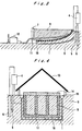
- Fig. 5 is a cross section of a waste disposal landfill based on the former leakage/diffusion protection method.
- a thin rubber-made shielding sheet 10 with a thickness of approximately 1-2 mm, is spread over a surface of sloping soil 9, the lower part of the slope is closed with a dam 7, and a waste 8 is dumped on the shielding sheet inside of the dam, which is then reclaimed.
- the seepage water containing the hazardous substances, harmful substances, and the like, which oozes out of the waste is shielded by the shielding sheet and does not leak into the environment.
- the seepage water is collected from the surface of a water-collecting tube 11 and transferred to seepage-water-treating equipment 12 in which it is treated and purged, and thereafter it is released into the environment.
- Fig. 6 is a cross section of a waste disposal landfill based on the latter leakage/diffusion protection method.
- the waste 8 is stored in exterior-walled equipment 16 having inside partition equipment 17. These equipments are made from concrete having unconfined compression strength of 250 kg/cm 2 or above, and a thickness of 10 cm or above and 15 cm or above, respectively.
- the waste is then covered by a cover 14, and the waste disposal landfill is provided with equipment to prevent the inflow of natural water, such as rainwater and the like, for example, equipment for preventing the inflow of rainwater 13, an open channel 15, and the like.
- natural water such as rainwater and the like
- the aforementioned conventional method of treating the waste in which a shielding rubber sheet is spread on the bottom of a disposal landfill, and the waste is dumped thereon, and the seepage water from the waste is treated by transferring from a water-collecting tube mounted on the rubber sheet to seepage water-treating equipment; or the method, in which the waste is completely sealed in concrete-made containing equipment buried under the ground, can prevent the leakage and diffusion of the hazardous substances, harmful substances, and the like, if the equipment used therein is complete. Since, however, both of the conventional methods physically intercept the seepage water and the hazardous substances, harmful substances, and the like, which are contained therein, they leak easily from a place of breakage in the equipment used, even if the equipment used is slightly damaged.
- An object of the present invention is to provide an electrode apparatus that has been developed in order to prevent environmental pollution by aforementioned leakage and diffusion of hazardous substances, harmful substances, and the like. That is, the electrode apparatus is one that is set around equipment, such as an aforementioned waste disposal landfill and the like, and that captures the hazardous substances, harmful substances, and the like, or renders them harmless by their oxidation/reduction reaction, to prevent them from leaking and diffusing into the ambient environment in the event of breakage of the equipment.
- Fig. 1 is a schematic structural view showing an example of an embodiment of an electrode apparatus of the present invention.
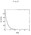
- Fig. 2 is a graph in which the ratio of the material concentration at an outlet, to that at an inlet, of a cylindrical electrode hole, is plotted versus the ratio of the length to the radius of the electrode hole.
- Fig. 3 is a view showing an example in which an electrode apparatus of the present invention is applied to a waste disposal landfill.
- Fig. 4 is a view showing another example in which an electrode apparatus of the present invention is applied to a waste disposal landfill.
- Fig. 5 is a view explaining a conventional technique of waste disposal.
- Fig. 6 is a view explaining another conventional technique of waste disposal.
- the present inventor having made many investigations devotedly in order to solve the aforementioned problems, has consequently attained the present invention.
- phenomenon of transfer or diffusion of hazardous or harmful substances, from an environment containing the substances in high concentration can be prevented. Then the soil around a general waste disposal landfill or industrial waste disposal landfill is prevented from transferring or diffusing the hazardous or harmful substances to an environment, such as the soil, river, an underground water vein, distant from the former environment.
- the present invention resides in:
- An example of an embodiment of the electrode apparatus of the present invention is shown in Fig. 1.
- An electrode (conductor) 1, preferably in a plate shape, is made from iron, aluminum, copper, steel materials, such as carbon steel or stainless steel, or other metals; graphite, or organic substances, such as conductive polymers and the like, and it has a structure through which perforations (electrode hole) 2 is bored.
- the preferable shape of the perforation is cylindrical, but it is possible to use perforations having another crosswise profile, such as a polygon and the like.
- the number of perforations is not restricted, and an appropriate number can be chosen depending on the material's physical strength and the like.
- the ratio of the total area of the cross section of the perforations occupied in unit area of the cross section of the electrode; that is, the so-called opening ratio, is set at 20% or above.
- the hole diameter of a perforation is not specifically restricted.
- the particularly preferable diameter of a perforation is within a range of 0.5 to 2 mm (radius of 0.25 to 1 mm). However, a diameter exceeding the range may be used, as long as the ratio of the length to the electrode hole diameter is set sufficiently (preferably 1 or above, more preferably 5 or above) so as to capture the hazardous or harmful substances, or render them harmless on the inner surface of the perforations, when the hazardous or harmful substances passes through the perforations.
- the electrode 1 is set in a conductive environment, such as the soil, an aqueous solution, and the like.
- the electrode 1 is connected through an electric source 4 to a reference electrode 5, used as standard for electric potential, and a counter electrode 6, which is a counter party to which an oxidation-reduction electric current is caused.
- a reference electrode may be used an electrode having a stable electric potential, such as a saturated copper sulfate electrode (Cu
- an iron or steel plate having a large surface area may be used in the soil and the like.
- the counter electrode used may be a conductive substance, such as metal and the like.
- the electric source 4 it is sufficient to use a conventional system that can maintain the electrode at a constant electric potential for proceeding an electrode reaction. This is shown in, for example, "New Edition Electrochemical Measurement Method” Electro-Chemical Society of Japan, PP. 9 ⁇ 10 (September 1988).
- the electric source 4 has a function of automatically controlling the electric potential between the electrode 1 and the counter electrode 6, and an electric current flowing between them, so as to automatically keep the electric potential between the electrode 1 and the reference electrode 5 constant cooperatively with that, while detecting the electric potential between the electrode 1 and the reference electrode 5.
- the electrode When the electrode is maintained at an appropriate oxidation-reduction electric potential to the reference electrode, to capture the hazardous or harmful substances (substances to be treated) 3, or to render them harmless, the hazardous or harmful substances, transferring in the direction of the arrow shown in Fig. 1 are oxidized or reduced on the inner surface of the perforations while diffusing in the perforations. At this time, an oxidation-reduction electric current flows between the electrode and the counter electrode 6 according to the electrode reaction.
- the electric potential of the electrode is set at a nobler (more positive) electric potential (higher electric potential) than an equilibrium electric potential of the oxidation-reduction reaction of these substances, in the case of an oxidation reaction, or at an ignobler (more negative) electric potential (lower electric potential) than the equilibrium electric potential of the oxidation-reduction reaction of these substances, in the case of a reduction reaction, depending on the kind of the hazardous or harmful substances.
- the electric potential of the electrode is set at an electric potential apart from the equilibrium electric potential by preferably approximately 0.4 ⁇ 0.5 V or above, to increase the rate of the oxidation-reduction reaction on the surface of the electrode up to a rate by which the reaction proceeds completely.
- the oxidation-reduction reaction on the surface of the electrode used in the present invention in the case of, for example, a metal ion, there is a reaction in which the metal ion is deposited as metal in the perforations and captured by using primarily the following reduction reaction: M m+ + me - ⁇ M wherein M m+ is a metal ion, and M is a metal.
- the compound is decomposed primarily by the following oxidation or reduction reaction, to make it harmless: O ⁇ O' + ne - O + ne - ⁇ O' ' wherein O is an organic compound and the like, and O', O", and the like are harmless compounds produced by an oxidation-reduction reaction of the O.
- O is an organic compound and the like
- O', O" and the like are harmless compounds produced by an oxidation-reduction reaction of the O.
- plural compounds are concerned with for reactants as well as products, and sometimes the reactants and products are compounds having an electric charge (ion) or having no electric charge. Further, sometimes the harmless compounds are finally produced through plural reactions of two steps or more.
- reaction (1) a reaction in which lead is deposited in an aqueous solution by a reduction reaction is shown in reaction (4).
- reaction (2) a reaction in which formalin (formaldehyde) converts to carbon dioxide by an oxidation reaction, also in an aqueous solution, is shown in reactions (5) and (6) (two-step reaction).
- Fig. 2 shows the change in the material concentration at the outlet of the perforation, with the change of the perforation radius and the perforation length obtained by using equation (7).
- Fig. 2 shows the ratio of the change in the material concentration at an outlet section and an inlet section of the perforation (C(r,Z o )/C o ) versus the ratio Z o /R o , when the perforation radius is R o and the perforation length is Z o .
- the perforation length is twofold, or more, larger than the perforation radius, it is possible to lower the material concentration to approximately 1/100 or below.
- the perforation length when carrying out the present invention, it is preferable for the perforation length to be approximately two times or more of the perforation radius, and, more preferably, by setting it at four times or more, thereby the diffusion of the hazardous or harmful substances can be almost completely prevented.
- plural electrodes may be used, stacked or placed side by side, so that the sum of the length of the perforation of the electrodes comes to the above-mentioned value.
- Equation (7) can be applied equally to a substance having no electric charge, as well as to an electrically charged substance, such as an ion. Further, since equation (7) does not depend on a physical constant inherent in a substance, such as the diffusion coefficient of the substance, and the like, the above-mentioned result can be applied equally to any kind of substance, and it is not necessary to change the perforation length and the like dependently on the substance to be treated.
- the reference electrode is one thing and the counter electrode is another, it is possible to omit the counter electrode by connecting electric wires used for the reference electrode and the counter electrode with the reference electrode, making the reference electrode have the function of the counter electrode. Thus it is possible to use only two electrodes of the electrode and the reference electrode. Further, since according to the present invention, the hazardous or harmful substances are captured and rendered harmless, only inside the perforations, it is also effective to coat the electrode surface, except the inner surface of the perforations, with an insulating resin and the like, in order to avoid excessive electrical-power consumption, suppressing the oxidation-reduction reaction at the insulated portion.
- the electrode apparatus of the present invention can prevent the transfer and/or diffusion of hazardous or harmful substances into an environment having a low concentration of hazardous or harmful substances. This is attained by setting the electrode, having perforations that are maintained at an oxidation-reduction electric potential sufficient to capture the hazardous or harmful substances, or render them harmless, for an environment containing a high concentration of the hazardous or harmful substances. Thus the electrode captures the hazardous or harmful substances or renders them harmless by the redox reaction, when a solution containing a high concentration of the hazardous or harmful substances passes through the.perforations.
- the diffusion and/or leakage of the hazardous or harmful substances into the ambient environment because of breakage of a shielding sheet, exterior barrier equipment, and so on, which are set in a general waste disposal landfill or industrial waste disposal landfill, can be efficiently prevented. Then the industrial significance of the present invention is of great important.
- An electrode apparatus of the present invention is applied for the purpose of preventing a lead ion, which is contained in high proportion in seepage water, from diffusing into the ambient environment from the systems of a waste disposal landfill as shown in Figs. 5 and 6, when a shielding sheet and exterior barrier equipment used in the system are damaged.
- the same symbol means the same members in the present specification and drawings.
- Fig. 3 shows an example in which the present invention is applied to the system of the waste disposal landfill of Fig 5.
- An electrode 1 to be used in the present invention is set by burying it in the soil in the vicinity of a shielding sheet 10. Alternatively, it may be set only in a water passageway, through which the seepage water flows into the underground water.
- An electric source 4, a reference electrode 5, and a counter electrode 6 are connected to the electrode 1, which is maintained at a constant electric potential in relation to the reference electrode 5. At this time, an electric current forms a circuit, in which it flows through the electric source 4, the electrode 1, and the conductive environment (soil) in which the electrode 1 is set, and it returns again to the electric source 4 via the counter electrode 6.
- the reference electrode 5 is set in order to monitor the electric potential between the electrode 1 and the reference electrode 5, an electric current scarcely flows from the reference electrode 5 to the electric source.
- a plate of steel, copper, aluminum, and so on, 2 mm thick, is used for the electrode 1
- a saturated copper sulfate electrode is used for the reference electrode 5
- a plate of steel, 2 mm thick is used for the counter electrode.
- the surface of the steel plate used for the electrode 1 is coated with an insulating resin, such as enamel and the like, and through the steel plate, a cylindrical perforation 2, of 1 mm diameter, is drilled, at a rate of 25 perforations per 1 cm 2 , so as to expose the surface of the metal only to the inner surface of the perforations.
- the opening ratio at this time is approximately 20%, and the ratio of the length to the perforation diameter is 4.
- the lead ion is converted to metal lead by a reduction reaction of reaction (4). Since the equilibrium electric potential of the reduction reaction is -0.4 to -0.5 V at room temperature, when a saturated copper sulfate electrode is used for the reference electrode, it is possible to promote the reaction (4) at sufficient rate if the electric potential of the electrode is maintained at the order of approximately -0.9 V. If the electrode is maintained at this electric potential, the seepage water that leaks out of the waste 8, because of breakage of the shielding sheet 10, reaches the electrode, and the lead ion in the seepage water is reduced to metal lead in the perforations, and it is deposited and captured on the inner surface of the perforations, and it does not diffuse into the ambient soil or underground water downstream from the water passageway. For example, the concentration of lead ion in the seepage water of 100 ppm or above could be lowered to approximately 0 ppm.
- Fig. 4 is another example in which the present invention is applied to a system of the waste disposal landfill as shown in Fig. 6.
- the electrode 1 is set in closely contact with the outside of the exterior-walled equipment 16, or it is set in the soil in the vicinity thereof, or it is set in a water passageway in the vicinity thereof.
- the electrode 1 is connected to the electric source 4, reference electrode 5, and counter electrode 6, and it is maintained at a constant electric potential.
- the shape, material, surface treatment, and the like of the electrode and the perforations to be used are the same as in the case of Fig. 3. Further, a reduction reaction of equation (4) is used, and the same reference electrode and counter electrode are used, and the electric potential is maintained similarly at approximately - 0.9 V.
- the electrode was set outside the shielding sheet or the exterior-walled equipment in the above-described examples, the electrode, having proper thickness and mechanical strength, can be used as the shielding sheet or exterior-walled equipment itself. Further, the present invention can be used not only to prevent diffusion of hazardous or harmful substances, it can also be used as a monitoring apparatus for leakage of hazardous or harmful substances, not by forming the electrode in one-piece but by forming it into plural pieces, which are set around the waste disposal landfill, to each of which a voltage is loaded, to detect an electric current caused by an oxidation-reduction reaction of the hazardous or harmful substances, by means of an ammeter connected in series between the electrodes and the electric source.
- the present invention can be used not only in the soil, it can also be used in order to prevent diffusion of the hazardous or harmful substances into an area that does not contain them by setting the electrode of the invention in natural water, such as seawater, a river, and the like, or in an aqueous solution containing the hazardous or harmful substances, such as industrial wastewater and the like.
Landscapes
- Chemical & Material Sciences (AREA)
- Engineering & Computer Science (AREA)
- Environmental & Geological Engineering (AREA)
- Chemical Kinetics & Catalysis (AREA)
- Organic Chemistry (AREA)
- Life Sciences & Earth Sciences (AREA)
- Metallurgy (AREA)
- Electrochemistry (AREA)
- Materials Engineering (AREA)
- Geology (AREA)
- Manufacturing & Machinery (AREA)
- Geochemistry & Mineralogy (AREA)
- General Life Sciences & Earth Sciences (AREA)
- Mechanical Engineering (AREA)
- General Chemical & Material Sciences (AREA)
- Soil Sciences (AREA)
- Hydrology & Water Resources (AREA)
- Water Supply & Treatment (AREA)
- Processing Of Solid Wastes (AREA)
- Water Treatment By Electricity Or Magnetism (AREA)
- Electrodes For Compound Or Non-Metal Manufacture (AREA)
Claims (5)
- Procédé de traitement de substances nocives ou dangereuses pour protéger un environnement contre toute fuite des substances nocives ou dangereuses en utilisant un appareil à électrode comprenant une électrode (1) composée d'un conducteur à travers laquelle des perforations (2) sont formées depuis une surface jusqu'à une surface de support, caractérisé en ce qu'une solution à traiter comprenant les substances nocives ou dangereuses traverse les perforations (2), et en ce que le conducteur est maintenu à un potentiel électrique suffisant pour provoquer une réaction d'oxydation ou de réduction dans les substances nocives ou dangereuses à l'intérieur des perforations.
- Procédé selon la revendication 1, dans lequel la solution passe par des perforations cylindriques, dont la longueur des perforations (2) entre les deux surfaces est approximativement deux fois, ou davantage, supérieure au rayon des perforations (2).
- Procédé selon la revendication 1 ou 2, dans lequel un conducteur à plaque est utilisé comme conducteur, le conducteur à plaque étant maintenu à un potentiel électrique, pour une contre-électrode prévue dans le sol, suffisant pour provoquer une réaction d'oxydation ou de réduction dans les substances à traiter.
- Procédé selon l'une quelconque des revendications précédentes, dans lequel l'environnement à protéger est le sol autour d'une décharge générale ou d'une décharge industrielle ou une solution aqueuse de traitement industriel.
- Utilisation d'un appareil à électrode pour traiter des substances nocives ou dangereuses, l'appareil à électrode comprenant une électrode (1) composée d'un conducteur à travers laquelle des perforations (2) sont formées depuis une surface jusqu'à une surface de support, caractérisée en ce que le conducteur est maintenu à un potentiel électrique suffisant pour provoquer une réaction d'oxydation ou de réduction dans les substances nocives ou dangereuses à traiter d'une solution admise à partir d'une entrée des perforations (2) et ayant traversé les perforations, afin de piéger ou de rendre les substances sans danger par leur réaction d'oxydation ou de réduction à l'intérieur des perforations (2), où la solution, dont la concentration est réduite, est diffusée à partir d'une sortie des perforations (2).
Applications Claiming Priority (2)
| Application Number | Priority Date | Filing Date | Title |
|---|---|---|---|
| JP34371398A JP3243493B2 (ja) | 1998-12-03 | 1998-12-03 | 電極装置 |
| JP34371398 | 1998-12-03 |
Publications (2)
| Publication Number | Publication Date |
|---|---|
| EP1008662A1 EP1008662A1 (fr) | 2000-06-14 |
| EP1008662B1 true EP1008662B1 (fr) | 2003-11-05 |
Family
ID=18363684
Family Applications (1)
| Application Number | Title | Priority Date | Filing Date |
|---|---|---|---|
| EP99124237A Expired - Lifetime EP1008662B1 (fr) | 1998-12-03 | 1999-12-03 | Traitement de solutions en utilisant un dispositif électrochimique à électrode conductrice perforée |
Country Status (4)
| Country | Link |
|---|---|
| US (1) | US6605203B1 (fr) |
| EP (1) | EP1008662B1 (fr) |
| JP (1) | JP3243493B2 (fr) |
| DE (1) | DE69912567T2 (fr) |
Cited By (13)
| Publication number | Priority date | Publication date | Assignee | Title |
|---|---|---|---|---|
| US7836543B2 (en) | 2006-02-10 | 2010-11-23 | Tennant Company | Method and apparatus for producing humanly-perceptable indicator of electrochemical properties of an output cleaning liquid |
| US7891046B2 (en) | 2006-02-10 | 2011-02-22 | Tennant Company | Apparatus for generating sparged, electrochemically activated liquid |
| US8007654B2 (en) | 2006-02-10 | 2011-08-30 | Tennant Company | Electrochemically activated anolyte and catholyte liquid |
| US8012339B2 (en) | 2006-02-10 | 2011-09-06 | Tennant Company | Hand-held spray bottle having an electrolyzer and method therefor |
| US8012340B2 (en) | 2006-02-10 | 2011-09-06 | Tennant Company | Method for generating electrochemically activated cleaning liquid |
| US8016996B2 (en) | 2006-02-10 | 2011-09-13 | Tennant Company | Method of producing a sparged cleaning liquid onboard a mobile surface cleaner |
| US8025787B2 (en) | 2006-02-10 | 2011-09-27 | Tennant Company | Method and apparatus for generating, applying and neutralizing an electrochemically activated liquid |
| US8046867B2 (en) | 2006-02-10 | 2011-11-01 | Tennant Company | Mobile surface cleaner having a sparging device |
| US8236147B2 (en) | 2008-06-19 | 2012-08-07 | Tennant Company | Tubular electrolysis cell and corresponding method |
| US8319654B2 (en) | 2008-06-19 | 2012-11-27 | Tennant Company | Apparatus having electrolysis cell and indicator light illuminating through liquid |
| US8337690B2 (en) | 2007-10-04 | 2012-12-25 | Tennant Company | Method and apparatus for neutralizing electrochemically activated liquids |
| US8371315B2 (en) | 2008-12-17 | 2013-02-12 | Tennant Company | Washing systems incorporating charged activated liquids |
| US8485140B2 (en) | 2008-06-05 | 2013-07-16 | Global Patent Investment Group, LLC | Fuel combustion method and system |
Families Citing this family (5)
| Publication number | Priority date | Publication date | Assignee | Title |
|---|---|---|---|---|
| DE10035497A1 (de) * | 2000-07-19 | 2002-01-31 | Enbw Ag | Verfahren und Elektrode zum elektrokinetischen Sanieren von schadstoffbelastetem, Porenflüssigkeit enthaltenden Erdboden |
| US8025786B2 (en) * | 2006-02-10 | 2011-09-27 | Tennant Company | Method of generating sparged, electrochemically activated liquid |
| US20070235344A1 (en) * | 2006-04-06 | 2007-10-11 | Applied Materials, Inc. | Process for high copper removal rate with good planarization and surface finish |
| JP6240041B2 (ja) * | 2013-11-28 | 2017-11-29 | 鹿島建設株式会社 | 埋立処分場における浸出水処理方法および浸出水処理システム |
| CN113275376A (zh) * | 2021-06-24 | 2021-08-20 | 南通大学 | 一种修复污染软黏土的装置及其修复方法 |
Family Cites Families (13)
| Publication number | Priority date | Publication date | Assignee | Title |
|---|---|---|---|---|
| DE2209917A1 (de) * | 1972-03-02 | 1973-09-20 | Metallgesellschaft Ag | Elektrode, insbesondere anode |
| JPS4917369A (fr) | 1972-06-12 | 1974-02-15 | ||
| US4367132A (en) * | 1980-08-27 | 1983-01-04 | Electro-Petroleum, Inc. | Method for removing liquid from chemically-precipitated sludge |
| EP0080288B1 (fr) * | 1981-11-24 | 1987-10-07 | Imperial Chemical Industries Plc | Cellule électrolytique de type filter-press |
| FI76773C (fi) | 1986-08-04 | 1990-02-19 | Erkki Haeivaelae | Foerfarande foer elektrolytisk behandling av skadliga komponenter, saosom cyanid innehaollande avloppsvatten och vid foerfarandet anvaendbar anordning. |
| JPS644996A (en) | 1987-06-26 | 1989-01-10 | Hitachi Ltd | Magnetic disk device |
| NL8702437A (nl) * | 1987-10-13 | 1989-05-01 | Geo Kinetics B V I O | Werkwijze voor het conditioneren van grondmateriaal door elektrokinetische behandeling, elektrisch stroomsysteem voor toepassing van de werkwijze alsmede elektrode-behuizing voor toepassing in het elektrische stroomsysteem. |
| US5074986A (en) * | 1989-06-06 | 1991-12-24 | Massachusetts Institute Of Technology | Electroosmosis techniques for removing materials from soil |
| DE4000505C1 (fr) * | 1990-01-10 | 1991-05-08 | Hoechst Ag, 6230 Frankfurt, De | |
| JPH0787912B2 (ja) | 1991-08-31 | 1995-09-27 | 山嵜 照彦 | 汚染土壌の処理方法とその装置 |
| JPH08281247A (ja) | 1995-04-11 | 1996-10-29 | Shigeru Orito | 電気化学的処理法 |
| US5534124A (en) * | 1995-09-19 | 1996-07-09 | Chem-Pro | On-site electrochemical dehalogenation process and system |
| US6171719B1 (en) * | 1996-11-26 | 2001-01-09 | United Technologies Corporation | Electrode plate structures for high-pressure electrochemical cell devices |
-
1998
- 1998-12-03 JP JP34371398A patent/JP3243493B2/ja not_active Expired - Lifetime
-
1999
- 1999-12-03 US US09/453,405 patent/US6605203B1/en not_active Expired - Fee Related
- 1999-12-03 DE DE69912567T patent/DE69912567T2/de not_active Expired - Lifetime
- 1999-12-03 EP EP99124237A patent/EP1008662B1/fr not_active Expired - Lifetime
Cited By (16)
| Publication number | Priority date | Publication date | Assignee | Title |
|---|---|---|---|---|
| US8156608B2 (en) | 2006-02-10 | 2012-04-17 | Tennant Company | Cleaning apparatus having a functional generator for producing electrochemically activated cleaning liquid |
| US8007654B2 (en) | 2006-02-10 | 2011-08-30 | Tennant Company | Electrochemically activated anolyte and catholyte liquid |
| US8012339B2 (en) | 2006-02-10 | 2011-09-06 | Tennant Company | Hand-held spray bottle having an electrolyzer and method therefor |
| US8012340B2 (en) | 2006-02-10 | 2011-09-06 | Tennant Company | Method for generating electrochemically activated cleaning liquid |
| US8016996B2 (en) | 2006-02-10 | 2011-09-13 | Tennant Company | Method of producing a sparged cleaning liquid onboard a mobile surface cleaner |
| US7891046B2 (en) | 2006-02-10 | 2011-02-22 | Tennant Company | Apparatus for generating sparged, electrochemically activated liquid |
| US8025787B2 (en) | 2006-02-10 | 2011-09-27 | Tennant Company | Method and apparatus for generating, applying and neutralizing an electrochemically activated liquid |
| US7836543B2 (en) | 2006-02-10 | 2010-11-23 | Tennant Company | Method and apparatus for producing humanly-perceptable indicator of electrochemical properties of an output cleaning liquid |
| US8046867B2 (en) | 2006-02-10 | 2011-11-01 | Tennant Company | Mobile surface cleaner having a sparging device |
| US8719999B2 (en) | 2006-02-10 | 2014-05-13 | Tennant Company | Method and apparatus for cleaning surfaces with high pressure electrolyzed fluid |
| US8603320B2 (en) | 2006-02-10 | 2013-12-10 | Tennant Company | Mobile surface cleaner and method for generating and applying an electrochemically activated sanitizing liquid having O3 molecules |
| US8337690B2 (en) | 2007-10-04 | 2012-12-25 | Tennant Company | Method and apparatus for neutralizing electrochemically activated liquids |
| US8485140B2 (en) | 2008-06-05 | 2013-07-16 | Global Patent Investment Group, LLC | Fuel combustion method and system |
| US8236147B2 (en) | 2008-06-19 | 2012-08-07 | Tennant Company | Tubular electrolysis cell and corresponding method |
| US8319654B2 (en) | 2008-06-19 | 2012-11-27 | Tennant Company | Apparatus having electrolysis cell and indicator light illuminating through liquid |
| US8371315B2 (en) | 2008-12-17 | 2013-02-12 | Tennant Company | Washing systems incorporating charged activated liquids |
Also Published As
| Publication number | Publication date |
|---|---|
| DE69912567T2 (de) | 2004-09-30 |
| US6605203B1 (en) | 2003-08-12 |
| JP2000167559A (ja) | 2000-06-20 |
| DE69912567D1 (de) | 2003-12-11 |
| JP3243493B2 (ja) | 2002-01-07 |
| EP1008662A1 (fr) | 2000-06-14 |
Similar Documents
| Publication | Publication Date | Title |
|---|---|---|
| US6605203B1 (en) | Electrode apparatus | |
| US11635406B2 (en) | Microbial sensor system for the assessment of subsurface environments | |
| Sigg | Redox potential measurements in natural waters: significance, concepts and problems | |
| CA1338863C (fr) | Procede electrique de remise en etat d'un sol, systeme electrique et boitier d'electrode connexes | |
| Flora et al. | Numerical modeling of a biofilm-electrode reactor used for enhanced denitrification | |
| US20030035691A1 (en) | Permeable-reactive barrier monitoring method and system | |
| AU5833600A (en) | Electrode | |
| CA2098511C (fr) | Systeme de traitement in situ pour empecher l'acidification de l'eau ou attenuer l'acidite | |
| JP3051034U (ja) | 廃棄物処分場 | |
| JP3495724B2 (ja) | 窒素処理方法 | |
| JPH11216441A (ja) | 廃棄物処分方法 | |
| KR102934241B1 (ko) | Iot 기반 블록조립형 빗물 식수화 시스템 | |
| CN121974442A (zh) | 一种六价铬污染地下水绿色修复系统及应用 | |
| JP4818074B2 (ja) | 地下水含有イオン濃度の連続測定方法および連続測定装置 | |
| Bell et al. | Investigation of corrosion mechanisms and control for encased ductile iron pipe | |
| CN101135057A (zh) | 电极 | |
| Su et al. | Galvanic Corrosion Behavior Between Copper (T2) and Carbon Steel (Q235) in Simulated Deep Geological Environment | |
| RU2075542C1 (ru) | Способ защиты от коррозии | |
| JPH09329521A (ja) | 廃棄物処分場における浸水検知装置 | |
| WO1995012037A1 (fr) | Barrieres de radon activees par electricite | |
| Eschenburg et al. | Design Challenges of a Corrosion Monitoring Network of the Environmental Subsurface Subject to Saltwater Intrusion | |
| Johnsen et al. | Cathodic Protection in Cold Seawater–Current Density Requirements | |
| Betts | Technology Update: Phytic acid immobilizes radionuclides | |
| Lingvay et al. | Technical solution and solid state devices for increase of durability and reliability of underground power lines (UPL) | |
| Fenton et al. | Preliminary steps in the location of a farm-scale groundwater remediation system |
Legal Events
| Date | Code | Title | Description |
|---|---|---|---|
| PUAI | Public reference made under article 153(3) epc to a published international application that has entered the european phase |
Free format text: ORIGINAL CODE: 0009012 |
|
| 17P | Request for examination filed |
Effective date: 19991206 |
|
| AK | Designated contracting states |
Kind code of ref document: A1 Designated state(s): CH DE FR GB LI |
|
| AX | Request for extension of the european patent |
Free format text: AL;LT;LV;MK;RO;SI |
|
| AKX | Designation fees paid |
Free format text: CH DE FR GB LI |
|
| 17Q | First examination report despatched |
Effective date: 20010903 |
|
| GRAH | Despatch of communication of intention to grant a patent |
Free format text: ORIGINAL CODE: EPIDOS IGRA |
|
| RTI1 | Title (correction) |
Free format text: TREATMENT OF SOLUTIONS BY USE OF ELECTRODE APPARATUS WITH PERFORATED CONDUCTOR ELECTRODE |
|
| GRAS | Grant fee paid |
Free format text: ORIGINAL CODE: EPIDOSNIGR3 |
|
| GRAA | (expected) grant |
Free format text: ORIGINAL CODE: 0009210 |
|
| AK | Designated contracting states |
Kind code of ref document: B1 Designated state(s): CH DE FR GB LI |
|
| REG | Reference to a national code |
Ref country code: GB Ref legal event code: FG4D |
|
| REG | Reference to a national code |
Ref country code: CH Ref legal event code: EP |
|
| RAP2 | Party data changed (patent owner data changed or rights of a patent transferred) |
Owner name: SECRETARY OF AGENCY OF NATIONAL INSTITUTE OF ADVAN |
|
| REF | Corresponds to: |
Ref document number: 69912567 Country of ref document: DE Date of ref document: 20031211 Kind code of ref document: P |
|
| RAP2 | Party data changed (patent owner data changed or rights of a patent transferred) |
Owner name: NATIONAL INSTITUTE OF ADVANCED INDUSTRIAL SCIENCE |
|
| REG | Reference to a national code |
Ref country code: CH Ref legal event code: NV Representative=s name: E. BLUM & CO. PATENTANWAELTE |
|
| ET | Fr: translation filed | ||
| PLBE | No opposition filed within time limit |
Free format text: ORIGINAL CODE: 0009261 |
|
| STAA | Information on the status of an ep patent application or granted ep patent |
Free format text: STATUS: NO OPPOSITION FILED WITHIN TIME LIMIT |
|
| 26N | No opposition filed |
Effective date: 20040806 |
|
| REG | Reference to a national code |
Ref country code: CH Ref legal event code: PFA Owner name: NATIONAL INSTITUE OF ADVANCED INDUSTRIAL SCIENCE Free format text: NATIONAL INSTITUE OF ADVANCED INDUSTRIAL SCIENCE AND TECHNOLOGY#1-3, KASUMIGASEKI 1-CHOME, CHIYODA-KU#TOKYO-TO 100-8921 (JP) -TRANSFER TO- NATIONAL INSTITUE OF ADVANCED INDUSTRIAL SCIENCE AND TECHNOLOGY#1-3, KASUMIGASEKI 1-CHOME, CHIYODA-KU#TOKYO-TO 100-8921 (JP) |
|
| PGFP | Annual fee paid to national office [announced via postgrant information from national office to epo] |
Ref country code: CH Payment date: 20091224 Year of fee payment: 11 |
|
| PGFP | Annual fee paid to national office [announced via postgrant information from national office to epo] |
Ref country code: GB Payment date: 20091218 Year of fee payment: 11 Ref country code: FR Payment date: 20100108 Year of fee payment: 11 |
|
| PGFP | Annual fee paid to national office [announced via postgrant information from national office to epo] |
Ref country code: DE Payment date: 20091222 Year of fee payment: 11 |
|
| REG | Reference to a national code |
Ref country code: CH Ref legal event code: PL |
|
| GBPC | Gb: european patent ceased through non-payment of renewal fee |
Effective date: 20101203 |
|
| REG | Reference to a national code |
Ref country code: FR Ref legal event code: ST Effective date: 20110831 |
|
| PG25 | Lapsed in a contracting state [announced via postgrant information from national office to epo] |
Ref country code: LI Free format text: LAPSE BECAUSE OF NON-PAYMENT OF DUE FEES Effective date: 20101231 Ref country code: FR Free format text: LAPSE BECAUSE OF NON-PAYMENT OF DUE FEES Effective date: 20110103 Ref country code: CH Free format text: LAPSE BECAUSE OF NON-PAYMENT OF DUE FEES Effective date: 20101231 |
|
| REG | Reference to a national code |
Ref country code: DE Ref legal event code: R119 Ref document number: 69912567 Country of ref document: DE Effective date: 20110701 |
|
| PG25 | Lapsed in a contracting state [announced via postgrant information from national office to epo] |
Ref country code: DE Free format text: LAPSE BECAUSE OF NON-PAYMENT OF DUE FEES Effective date: 20110701 Ref country code: GB Free format text: LAPSE BECAUSE OF NON-PAYMENT OF DUE FEES Effective date: 20101203 |