EP1008680A2 - Ceinture de sécurité - Google Patents
Ceinture de sécurité Download PDFInfo
- Publication number
- EP1008680A2 EP1008680A2 EP99119734A EP99119734A EP1008680A2 EP 1008680 A2 EP1008680 A2 EP 1008680A2 EP 99119734 A EP99119734 A EP 99119734A EP 99119734 A EP99119734 A EP 99119734A EP 1008680 A2 EP1008680 A2 EP 1008680A2
- Authority
- EP
- European Patent Office
- Prior art keywords
- warp yarns
- group
- webbing
- yarns
- seat belts
- Prior art date
- Legal status (The legal status is an assumption and is not a legal conclusion. Google has not performed a legal analysis and makes no representation as to the accuracy of the status listed.)
- Granted
Links
Images

Classifications
-
- D—TEXTILES; PAPER
- D03—WEAVING
- D03D—WOVEN FABRICS; METHODS OF WEAVING; LOOMS
- D03D1/00—Woven fabrics designed to make specified articles
- D03D1/0005—Woven fabrics for safety belts
Definitions
- the present invention relates to seat belt webbing, and more particularly to an improved seat belt webbing having low longitudinal stiffness and reduced friction characteristics to assist in retraction and extraction of the seat belt.
- Seat belt (also called safety belt) systems have evolved significantly as these systems have become standard equipment in all types of automotive vehicles. Different designs of seat belts have been provided for various types of systems, depending upon the properties desired. It has been recognized that in order to provide an effective seat belt system, it is preferable that the seat belt webbing have various desirable characteristics.
- Desirable characteristics of seat belt webbing typically include: good lateral stiffness to help prevent roping or twisting of the seat belt, such as within the "D" ring upon extraction or retraction which could lead to a malfunction of the seat belt system; low longitudinal stiffness to reduce the retraction and extraction of the seat belt into and out of the seat belt winding mechanism; good abrasion resistance to help ensure a long product life; and passenger comfort to promote product use.
- the winding mechanism is used to retract the seat belt when not in use, and typically include a spool upon which the webbing is coiled as well as a spring for applying tension to the seat belt as it is extracted so that it can be automatically retracted when released by the user.
- the spring tension must be high enough so that the seat belt webbing will be fully retracted with reliability, but the spring tension must not be so great that it causes discomfort to the user as the seat belt is being fastened and worn.
- a main force resisting retraction of the seat belt webbing is friction generated between the surface of the seat belt webbing and the guide members of the seat belt restraint system through which it passes. All of these traits are now being considered more by purchasers of automobiles when evaluating overall automobile quality, and accordingly, are being carefully evaluated by manufacturers for improvement.
- the present invention is a webbing for seat belts having a plurality of warp yarns interwoven with a plurality of weft yarns which are inserted through a shed in the warp yarns.
- the warp yarns include a first group and a second group, with the second group of warp yarns having a higher density across a portion of the width of the shed than the warp yarns of the first group. At least some of the warp yarns in the second group are separated from one another by the warp yarns of the first group.
- the webbing has two faces and is flexible from a first, generally flat position to a second, flexed position.
- the first and second groups of warp yarns on one fabric face define a generally smooth surface.
- the webbing is in the second, flexed position, in which a first portion of the one fabric face is separated from a second portion of the one fabric face by a transition area, and the first portion is positioned generally at an angle ⁇ of less than 180° from the second portion of the one fabric face, at least a portion of the second group of warp yarns in the transition area protrude at least partially from the generally smooth surface to define a plurality of ribs.
- the present invention provides a webbing for seat belts having a plurality of warp yarns interwoven with a plurality of weft yarns.
- First and second groups of warp yarns are provided.
- the first group of warp yarns is interwoven with the weft yarns in a first weave pattern and the second group of warp yarns is interwoven with the weft yarns in a second weave pattern. At least some of the warp yarns in the second group are separated from one another by the warp yarns from the first group.
- the webbing has two faces and is flexible from a first, generally flat position to a second, flexed position. When the webbing is in the generally flat position, the first and second group of warp yarns on one fabric face define a generally smooth surface.
- the webbing When the webbing is in the second, flexed position, in which a first portion of the one fabric face is separated from a second portion of the one fabric face by a transition area, and the first portion is positioned generally at an angle ⁇ of less than 180° from the second portion of the one fabric face, at least a portion of the second group of warp yarns in the transition area protrude at least partially from the generally smooth surface to define a plurality of ribs.
- the present invention provides a seat belt system for motor vehicles comprising a seat belt webbing having a plurality of warp yarns interwoven with a plurality of weft yarns which are inserted through a shed in the warp yarns.
- First and second groups of warp yarns are provided.
- the second group of warp yarns having a higher density across a portion of the width of the shed than the warp yarns of the first group. At least some of the warp yarns in the second group are separated from one another by the warp yarns from the first group.
- a winding mechanism having a spool is provided and the seat belt webbing is at least partially coiled on the spool.
- a shoulder harness guide member is provided at a position generally corresponding to a user's shoulder, and a portion of the seat belt webbing passes over the shoulder harness guide member to redirect the seat belt webbing which extends from the winding mechanism.
- a buckle member is connected to the seat belt webbing.
- the seat belt webbing has two faces and is flexible from a first, generally flat position to a second, flexed position. When the webbing is in the generally flat position, the first and second groups of warp yarns on one fabric face define a generally smooth surface.
- the present invention provides a method of making a seat belt webbing.
- the method includes:
- a schematic illustration of a seat belt webbing 10 in accordance with the present invention is shown as it is being woven in a needle loom.
- the seat belt webbing 10 includes a plurality of warp yarns 11 which are interwoven with a plurality of weft or filling yarns 12 which are inserted through a shed in the warp yarns 11. While the weft yarns 12 may in fact be a single continuous strand, as used herein and as understood by those of ordinary skill in the art, the term "weft yarn” refers to each pass of the weft yarn across the shed.
- the seat belt webbing 10 is preferably woven on a conventional needle loom (not shown) which includes a filling insertion arm 13. However, it will be recognized by those skilled in the art from the present disclosure that other types of looms may be utilized, if desired.
- the webbing 10 is woven on a needle loom, and it is desirable to provide a knitted edge formation 43 along one edge of the webbing 10.
- the edge formation 43 provides for an effective and efficient production of the webbing 10, and the edge knitting 43 according to the invention is practiced by knitting either one or more catch cord yarns 44 and/or lock stitch yarns at the edge portion.
- the tension is controlled on the locking yarns to ensure a uniform edge, such as a Mueller System 3 or a System 5 edge.
- a locking yarn 44 may not be required along one edge of the webbing 10 to hold weft yarns 12 in place.
- the warp yarns 11 have a density which varies across a width of the shed which corresponds generally to the width of the webbing 10.
- the warp yarns 11 are divided into a first group 21 and a second group 31, with the second group 31 of warp yarns 11 having a higher density across their portion of the width of the shed than the warp yarns 11 of the first group 21. This can be accomplished by various means.
- the warp yarns 11 of the first group 21 are woven with the weft yarn 12 in a first weave pattern and the warp yarns 11 of the second group 31 are woven with the weft yarns 12 in a second weave pattern.
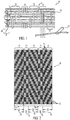
- the weave chart in Fig. 2 represents an edge portion 24 on one side of the webbing 10 and a full repeat 26 which is preferably repeated across the width of the webbing 10 until the opposite edge portion (not shown) is reached.
- the opposite edge portion is preferably a mirror image of the edge portion 24.
- at least some of the warp yarns 11 in the second group 31 are separated from one another by the warp yarns 11 from the first group 21.
- the first group of warp yarns 21 are woven with the weft yarns 12 in a four harness twill, with two weft yarns being provided in each shed due to the use of a needle loom.
- the second group 31 of the warp yarns 11 is divided into a number of equally spaced groupings 32, which are spaced apart by groupings 22 of the warp yarns 11 from the first group 21.
- there are at least three equally spaced groupings 32 of warp yarns 11 from the second group and in the preferred embodiment, there are eleven equally spaced groupings 32.
- any number of groupings 32 of warp yarns 11 from the second group 31 may be provided, and the spacing between the groupings 32 may be equal or unequal, depending on the particular requirements of a given application.
- the groupings 32 of the warp yarns 11 from the second group 31 are used to provide ribs 40, as will be described in more detail below in order to provide a seat belt webbing 10 with reduced friction characteristics.
- the density of the warp yarns 11 can also be varied by increasing the denier of the warp yarns 11 of the second group 31 relative to the warp yarns 11 of the first group 21.
- the warp yarns 11 of the second group 31 can be woven in pairs, as shown in Fig. 2, or in even greater numbers, by inserting multiple yarns through a single heddle eye in order to increase the density, while the warp yarns 11 in the first group 21 are preferably woven individually.
- the number of harnesses, the placement of the heddles in each harness, and/or the harness motion can be varied to vary the density of the warp yarns 11 across the width of the shed.
- each grouping 32 of the second group 31 includes at least a single warp yarn 11. More preferably, as shown in Fig. 2, each grouping 32 of warp yarns 11 of the second group 31 includes a pair of adjacent warp yarns 11 which have the same weave in order to provide an increased density. Additionally, in the preferred embodiment, each grouping 32 of warp yarns 11 of the second group 31 include first and second pairs of adjacent warp yarns, with the first and second pairs of adjacent warp yarns 11 being woven on opposite sides of each shed.
- weft yarns 12 can be inserted singly, and may be either monofilament or multi-filament yarns. Furthermore, weft yarns 12 may also be inserted in pairs, with one weft yarn being a monofilament and the other being a multi-filament in order to provide increased lateral stiffness for the webbing 10.
- the twill direction of the groupings 22 of warp yarns 11 in the first group 21 alternates on opposite sides of each grouping 32 of warp yarns 11 in the second group 31.
- any desired weave pattern can be utilized for the warp yarns 11 of the first group 21, such as a 2x2 twill, or any other weave suitable for automotive seat belt webbing.
- the webbing 10 has two faces 14, 15 and is flexible from a first generally flat position to a second, flexed position.
- the first and second groups 21, 31 of warp yarns 11 define a generally smooth surface.
- the ribs 40 are spaced apart at a predetermined distance, which is preferably based upon at least the lateral stiffness of the webbing 10, and preferably the lateral and longitudinal stiffness, such that at least some of the interwoven warp yarns 11 of the first group 21 which are located between adjacent ribs 40 are bridged over a guide member 42 which contacts the ribs 40 protruding from the one face 14 of the webbing 10 in the transition area 19 to reduce friction as the webbing 10 slides over the guide member 42.
- each rib 40 appears to be continuous in nature due to the adjacent pairs of warp yarns 11 of each grouping 32 being woven on opposite sides of each shed, such that as the webbing 10 is woven, the first and second adjacent pairs of warp yarns 11 in each grouping 32 are forced together and form a nearly continuous rib 40.
- the ribs 40 may be discontinuous, as illustrated schematically in Fig. 1, and that adjacent ribs 40 may have oppositely spaced weave patterns such that, while each rib 40 is discontinuous, preferably at least a portion of one of the ribs 40 in adjacent pairs of ribs 40 contacts the guide member 42 in the transition area 19 at any given time.
- the warp and weft yarns 11, 12 may be either single or multiple ply yarns of any given denier, and may be twisted or untwisted.
- the deniers of the warp and weft yarns 11, 12 are preferably chosen depending upon the type of yarn used and a particular customer's requirement. Additionally, different types of weft yarns or warp yarns may be used within a single webbing in order to obtain different properties from different yarns. For example, when the weft yarns 12 are inserted in pairs, one yarn may have different properties than the other yarn.
- the height, density and thickness of the ribs 40 as well as the locations selected for the ribs 40 may also be varied depending upon a particular customer's requirements and the ribs 40 may be spaced uniformly or non-uniformly, as desired.
- the warp yarns 11 are single ply polyester yarns having a denier of about 1300.
- the weft yarn 12 is preferably a multi-filament yarn comprised of polyester and having a denier of about 840.
- the catch cord 44 is preferably a polyester yarn having an denier of about 500.
- the webbing 10 preferably is provided with a good lateral stiffness, low longitudinal stiffness, abrasion resistance and enhanced user comfort due to the ribs 40 which protrude in the transition area 19 as the webbing 10 passes over a guide member 42 in a seat belt system. In the preferred embodiment, the webbing 10 is approximately two inches wide. However, the webbing 10 can be used in applications in which the width is preferably between 1.0 and 4.0 inches. It is also possible to make the webbing 10 in other narrower or wider sizes for various other applications. It is also possible to make the webbing with additional features including, but not limited to, standard and high elongations, and various round and other comfort edges.
- a seat belt system 48 is shown in detail and includes the seat belt webbing 10 which is provided on a winding mechanism 50 having a spool 52, with the seat belt webbing 10 being at least partially coiled on the spool 52.
- the shoulder harness guide member 42 is provided at a position generally corresponding to a user's shoulder, and the seat belt webbing 10 passes over the shoulder harness guide member 42 to redirect the seat belt webbing 10 which extends from the winding mechanism 52.
- a buckle member 54 is connected to the seat belt webbing 10 by passing through an opening in the buckle member 54, and the end of the seat belt webbing is anchored in a fixed position (not shown).
- the seat belt webbing 10 may be used in other types of retractable seat belt systems. As the seat belt webbing 10 is drawn across the guide member 42, the groupings 32 of warp yarns 11 in the second group 31 protrude from the generally smooth surface on the face 14 of the seat belt webbing 10 facing the guide member 42 to reduce friction.
- the webbing 10 is made by providing warp yarns 11 in a shed with the density of the warp yarns 11 being varied across the width of the shed.
- the first group 21 of the warp yarns 11 has a first density in a direction of the width of the shed and the second group 31 of warp yarns 11 have a second, higher density in the direction of the width of the shed, and at least some of the warp yarns 11 of the second group 31 are separated by warp yarns 11 of the first group 21.
- Weft yarns 12 are woven with the warp yarns 11 across the width of the shed and are preferably stitched along one edge of the webbing using a catch cord 44.
- Elevatable ribs 40 which are located longitudinally along the webbing 10 are formed from the second group 31 of warp yarns 11 which elevate from an inside surface 14 of the webbing 10 as the webbing 10 is folded in a longitudinal direction to produce a lateral fold.
Landscapes
- Engineering & Computer Science (AREA)
- Textile Engineering (AREA)
- Automotive Seat Belt Assembly (AREA)
- Woven Fabrics (AREA)
- Compositions Of Macromolecular Compounds (AREA)
Applications Claiming Priority (2)
| Application Number | Priority Date | Filing Date | Title |
|---|---|---|---|
| US09/170,645 US6199597B1 (en) | 1998-10-13 | 1998-10-13 | Seat belt webbing double faced with ribs |
| US170645 | 1998-10-13 |
Publications (3)
| Publication Number | Publication Date |
|---|---|
| EP1008680A2 true EP1008680A2 (fr) | 2000-06-14 |
| EP1008680A3 EP1008680A3 (fr) | 2001-06-20 |
| EP1008680B1 EP1008680B1 (fr) | 2004-02-18 |
Family
ID=22620730
Family Applications (1)
| Application Number | Title | Priority Date | Filing Date |
|---|---|---|---|
| EP99119734A Expired - Lifetime EP1008680B1 (fr) | 1998-10-13 | 1999-10-05 | Ceinture de sécurité |
Country Status (5)
| Country | Link |
|---|---|
| US (1) | US6199597B1 (fr) |
| EP (1) | EP1008680B1 (fr) |
| AT (1) | ATE259899T1 (fr) |
| CA (1) | CA2254458A1 (fr) |
| DE (1) | DE69914866T2 (fr) |
Families Citing this family (20)
| Publication number | Priority date | Publication date | Assignee | Title |
|---|---|---|---|---|
| US6510872B1 (en) * | 1999-07-07 | 2003-01-28 | Wayn-Tex, Incorporated | Carpet backing and methods of making and using the same |
| US6435220B1 (en) * | 1999-07-07 | 2002-08-20 | Wayn-Tex, Inc | Carpet backing and methods of making and using the same |
| KR20040033829A (ko) * | 2002-10-16 | 2004-04-28 | 현대자동차주식회사 | 시트 벨트 웨빙 직물의 구조 |
| US7178559B2 (en) * | 2003-09-11 | 2007-02-20 | Forrester Ketley & Co. | Webbing belt |
| JP2007534850A (ja) * | 2004-02-20 | 2007-11-29 | フェデラル−モーグル パワートレイン インコーポレイテッド | 低摩擦プルテープ |
| US7654618B2 (en) * | 2005-04-08 | 2010-02-02 | Tk Holdings Inc. | Webbing tack |
| US20070068731A1 (en) * | 2005-09-28 | 2007-03-29 | Sturges Manufacturing Co., Inc. | Energy absorber for personal fall arrestor |
| US7815013B2 (en) * | 2005-09-28 | 2010-10-19 | Sturges Manufacturing Co. | Energy absorber for personal fall arrestor |
| DE102006010775A1 (de) * | 2006-03-08 | 2007-09-13 | Johann Berger | Gurtband, Verfahren und Nadel-Bandwebmaschine zur Herstellung desselben |
| WO2008073301A2 (fr) * | 2006-12-08 | 2008-06-19 | Astenjohnson, Inc. | Dessin de tissage de couche côté machine pour fabrication de tissus composites |
| USD647043S1 (en) * | 2008-11-06 | 2011-10-18 | Chi Tzu Liao | Tread belt pattern |
| US8356691B2 (en) * | 2009-08-18 | 2013-01-22 | Sturges Manufacturing Co., Inc. | Energy absorber for personal fall arrestor |
| US8434527B2 (en) * | 2011-02-01 | 2013-05-07 | Autoliv Development Ab | Seat belt webbing and method for manufacturing the same |
| CN204342979U (zh) * | 2014-09-02 | 2015-05-20 | 宋海燕 | 一种局部编织加密的塑料编织布 |
| FR3037811B1 (fr) * | 2015-06-29 | 2018-05-25 | Zedel | Sangle formant ceinture et/ou paire de tours de cuisse de harnais d'encordement, et harnais d'encordement |
| JP1593350S (fr) * | 2016-09-01 | 2017-12-18 | ||
| JP1593349S (fr) * | 2016-09-01 | 2017-12-18 | ||
| CN110923895B (zh) * | 2019-11-11 | 2023-12-19 | 肇庆市鼎湖兴文塑胶五金制品有限公司 | 一种织带边缘收边的编织方法 |
| CN115027598B (zh) * | 2022-06-13 | 2023-07-14 | 江苏嗯哇科技有限公司 | 一种休闲两人电动三轮车 |
| EP4731823A1 (fr) * | 2023-06-23 | 2026-04-29 | Autoliv Development AB | Sangle de ceinture de sécurité |
Family Cites Families (9)
| Publication number | Priority date | Publication date | Assignee | Title |
|---|---|---|---|---|
| US4177839A (en) * | 1976-01-27 | 1979-12-11 | Nsk-Warner K.K. | Webbing for seat belt |
| DE2719382C3 (de) | 1977-04-30 | 1980-04-10 | 7070 Schwaebisch Gmuend | Verfahren und Nadel-Bandwebmaschine zur Herstellung eines Gurtbandes mit Hohlkanten |
| FI67100C (fi) | 1979-06-23 | 1985-01-10 | Berger Johann | Foerfarande och traodinfoerare foer framstaellning av ett goerdelband med en i ett lag vaevd mittdel och tvao ihaoliga kanter pao en naolbandvaevmaskin |
| JPH031493Y2 (fr) * | 1986-03-17 | 1991-01-17 | ||
| EP0285341A3 (fr) * | 1987-03-30 | 1990-06-27 | Nippon Seiko Kabushiki Kaisha | Sangle pour ceinture |
| JPH0651939B2 (ja) * | 1988-06-14 | 1994-07-06 | 菊地工業株式会社 | 無地織柄ベルト |
| US4981161A (en) * | 1988-11-17 | 1991-01-01 | Lagran Canada, Inc. | Seat belt webbing having multifilament and monofilament yarns |
| US5167263A (en) * | 1991-10-16 | 1992-12-01 | Kelen Steven I | Industrial high strength webbing |
| JPH09309405A (ja) * | 1996-05-21 | 1997-12-02 | Nippon Seiko Kk | シートベルト用ウェビング |
-
1998
- 1998-10-13 US US09/170,645 patent/US6199597B1/en not_active Expired - Fee Related
- 1998-11-24 CA CA002254458A patent/CA2254458A1/fr not_active Abandoned
-
1999
- 1999-10-05 AT AT99119734T patent/ATE259899T1/de not_active IP Right Cessation
- 1999-10-05 EP EP99119734A patent/EP1008680B1/fr not_active Expired - Lifetime
- 1999-10-05 DE DE69914866T patent/DE69914866T2/de not_active Expired - Fee Related
Also Published As
| Publication number | Publication date |
|---|---|
| DE69914866D1 (de) | 2004-03-25 |
| EP1008680A3 (fr) | 2001-06-20 |
| US6199597B1 (en) | 2001-03-13 |
| EP1008680B1 (fr) | 2004-02-18 |
| ATE259899T1 (de) | 2004-03-15 |
| DE69914866T2 (de) | 2005-01-05 |
| CA2254458A1 (fr) | 2000-04-13 |
Similar Documents
| Publication | Publication Date | Title |
|---|---|---|
| US6199597B1 (en) | Seat belt webbing double faced with ribs | |
| US4600626A (en) | Webbing suitable for use in vehicle seat belt system | |
| US4981161A (en) | Seat belt webbing having multifilament and monofilament yarns | |
| US6112775A (en) | Weft yarn selection mechanism and methods for weaving seat belt webbing | |
| EP3225726B1 (fr) | Sangle pour ceinture de protection du passager, ceinture de sécurité et appareil de ceinture de sécurité | |
| EP2003026B1 (fr) | Sangle étirable, ceinture gonflable et appareil à ceinture gonflable | |
| EP1514962B1 (fr) | Sangle de ceinture | |
| EP0119684A1 (fr) | Ceinture de sécurité à lisière douce | |
| US6375218B2 (en) | Airbelt and airbelt apparatus | |
| US8434527B2 (en) | Seat belt webbing and method for manufacturing the same | |
| JP4927821B2 (ja) | 帯紐ベルト | |
| EP1790762B1 (fr) | Bande pour ceinture de sécurité, ceinture de sécurité et dispositif de ceinture de sécurité | |
| JP5604065B2 (ja) | シートベルト用細幅織物 | |
| EP1932731B1 (fr) | Sangle pour ceinture de protection du passager, ceinture de sécurité et dispositif de ceinture de sécurité | |
| US6370924B1 (en) | Warp-knitted fabric for inflatable belt cover | |
| CN115698403B (zh) | 用于机动车辆的安全带装置的安全带 | |
| EP0285341A2 (fr) | Sangle pour ceinture | |
| JP6617568B2 (ja) | シートベルト用ウェビング | |
| JP2014133468A (ja) | シートベルト用ウェビング | |
| JP3757656B2 (ja) | エアベルトカバー用たて編み物、エアベルトカバー及びエアベルト装置 | |
| CA1306664C (fr) | Sangle pour ceinture de securite | |
| CN102618990B (zh) | 座椅安全带边带及其制造方法 | |
| JP2601978Y2 (ja) | シートベルト用ウェビング | |
| KR20260018893A (ko) | 시트 벨트 스트랩 | |
| JPH0424239A (ja) | シートベルト用ウエビング |
Legal Events
| Date | Code | Title | Description |
|---|---|---|---|
| PUAI | Public reference made under article 153(3) epc to a published international application that has entered the european phase |
Free format text: ORIGINAL CODE: 0009012 |
|
| AK | Designated contracting states |
Kind code of ref document: A2 Designated state(s): AT BE CH CY DE DK ES FI FR GB GR IE IT LI LU MC NL PT SE |
|
| AX | Request for extension of the european patent |
Free format text: AL;LT;LV;MK;RO;SI |
|
| PUAL | Search report despatched |
Free format text: ORIGINAL CODE: 0009013 |
|
| AK | Designated contracting states |
Kind code of ref document: A3 Designated state(s): AT BE CH CY DE DK ES FI FR GB GR IE IT LI LU MC NL PT SE |
|
| AX | Request for extension of the european patent |
Free format text: AL;LT;LV;MK;RO;SI |
|
| 17P | Request for examination filed |
Effective date: 20011109 |
|
| AKX | Designation fees paid |
Free format text: AT BE CH CY DE DK ES FI FR GB GR IE IT LI LU MC NL PT SE |
|
| GRAP | Despatch of communication of intention to grant a patent |
Free format text: ORIGINAL CODE: EPIDOSNIGR1 |
|
| GRAS | Grant fee paid |
Free format text: ORIGINAL CODE: EPIDOSNIGR3 |
|
| GRAA | (expected) grant |
Free format text: ORIGINAL CODE: 0009210 |
|
| RIN1 | Information on inventor provided before grant (corrected) |
Inventor name: DAVID, FREDERICK R. |
|
| AK | Designated contracting states |
Kind code of ref document: B1 Designated state(s): AT BE CH CY DE DK ES FI FR GB GR IE IT LI LU MC NL PT SE |
|
| PG25 | Lapsed in a contracting state [announced via postgrant information from national office to epo] |
Ref country code: NL Free format text: LAPSE BECAUSE OF FAILURE TO SUBMIT A TRANSLATION OF THE DESCRIPTION OR TO PAY THE FEE WITHIN THE PRESCRIBED TIME-LIMIT Effective date: 20040218 Ref country code: LI Free format text: LAPSE BECAUSE OF FAILURE TO SUBMIT A TRANSLATION OF THE DESCRIPTION OR TO PAY THE FEE WITHIN THE PRESCRIBED TIME-LIMIT Effective date: 20040218 Ref country code: IT Free format text: LAPSE BECAUSE OF FAILURE TO SUBMIT A TRANSLATION OF THE DESCRIPTION OR TO PAY THE FEE WITHIN THE PRE;WARNING: LAPSES OF ITALIAN PATENTS WITH EFFECTIVE DATE BEFORE 2007 MAY HAVE OCCURRED AT ANY TIME BEFORE 2007. THE CORRECT EFFECTIVE DATE MAY BE DIFFERENT FROM THE ONE RECORDED.SCRIBED TIME-LIMIT Effective date: 20040218 Ref country code: FR Free format text: LAPSE BECAUSE OF FAILURE TO SUBMIT A TRANSLATION OF THE DESCRIPTION OR TO PAY THE FEE WITHIN THE PRESCRIBED TIME-LIMIT Effective date: 20040218 Ref country code: FI Free format text: LAPSE BECAUSE OF FAILURE TO SUBMIT A TRANSLATION OF THE DESCRIPTION OR TO PAY THE FEE WITHIN THE PRESCRIBED TIME-LIMIT Effective date: 20040218 Ref country code: CY Free format text: LAPSE BECAUSE OF FAILURE TO SUBMIT A TRANSLATION OF THE DESCRIPTION OR TO PAY THE FEE WITHIN THE PRESCRIBED TIME-LIMIT Effective date: 20040218 Ref country code: CH Free format text: LAPSE BECAUSE OF FAILURE TO SUBMIT A TRANSLATION OF THE DESCRIPTION OR TO PAY THE FEE WITHIN THE PRESCRIBED TIME-LIMIT Effective date: 20040218 Ref country code: BE Free format text: LAPSE BECAUSE OF FAILURE TO SUBMIT A TRANSLATION OF THE DESCRIPTION OR TO PAY THE FEE WITHIN THE PRESCRIBED TIME-LIMIT Effective date: 20040218 Ref country code: AT Free format text: LAPSE BECAUSE OF FAILURE TO SUBMIT A TRANSLATION OF THE DESCRIPTION OR TO PAY THE FEE WITHIN THE PRESCRIBED TIME-LIMIT Effective date: 20040218 |
|
| REG | Reference to a national code |
Ref country code: GB Ref legal event code: FG4D |
|
| REG | Reference to a national code |
Ref country code: CH Ref legal event code: EP |
|
| REG | Reference to a national code |
Ref country code: IE Ref legal event code: FG4D |
|
| REF | Corresponds to: |
Ref document number: 69914866 Country of ref document: DE Date of ref document: 20040325 Kind code of ref document: P |
|
| PG25 | Lapsed in a contracting state [announced via postgrant information from national office to epo] |
Ref country code: SE Free format text: LAPSE BECAUSE OF FAILURE TO SUBMIT A TRANSLATION OF THE DESCRIPTION OR TO PAY THE FEE WITHIN THE PRESCRIBED TIME-LIMIT Effective date: 20040518 Ref country code: GR Free format text: LAPSE BECAUSE OF FAILURE TO SUBMIT A TRANSLATION OF THE DESCRIPTION OR TO PAY THE FEE WITHIN THE PRESCRIBED TIME-LIMIT Effective date: 20040518 Ref country code: DK Free format text: LAPSE BECAUSE OF FAILURE TO SUBMIT A TRANSLATION OF THE DESCRIPTION OR TO PAY THE FEE WITHIN THE PRESCRIBED TIME-LIMIT Effective date: 20040518 |
|
| PG25 | Lapsed in a contracting state [announced via postgrant information from national office to epo] |
Ref country code: ES Free format text: LAPSE BECAUSE OF FAILURE TO SUBMIT A TRANSLATION OF THE DESCRIPTION OR TO PAY THE FEE WITHIN THE PRESCRIBED TIME-LIMIT Effective date: 20040529 |
|
| NLV1 | Nl: lapsed or annulled due to failure to fulfill the requirements of art. 29p and 29m of the patents act | ||
| REG | Reference to a national code |
Ref country code: CH Ref legal event code: PL |
|
| PG25 | Lapsed in a contracting state [announced via postgrant information from national office to epo] |
Ref country code: LU Free format text: LAPSE BECAUSE OF NON-PAYMENT OF DUE FEES Effective date: 20041005 Ref country code: IE Free format text: LAPSE BECAUSE OF NON-PAYMENT OF DUE FEES Effective date: 20041005 Ref country code: GB Free format text: LAPSE BECAUSE OF NON-PAYMENT OF DUE FEES Effective date: 20041005 |
|
| PG25 | Lapsed in a contracting state [announced via postgrant information from national office to epo] |
Ref country code: MC Free format text: LAPSE BECAUSE OF NON-PAYMENT OF DUE FEES Effective date: 20041031 |
|
| PLBE | No opposition filed within time limit |
Free format text: ORIGINAL CODE: 0009261 |
|
| STAA | Information on the status of an ep patent application or granted ep patent |
Free format text: STATUS: NO OPPOSITION FILED WITHIN TIME LIMIT |
|
| EN | Fr: translation not filed | ||
| 26N | No opposition filed |
Effective date: 20041119 |
|
| GBPC | Gb: european patent ceased through non-payment of renewal fee |
Effective date: 20041005 |
|
| REG | Reference to a national code |
Ref country code: IE Ref legal event code: MM4A |
|
| PG25 | Lapsed in a contracting state [announced via postgrant information from national office to epo] |
Ref country code: PT Free format text: LAPSE BECAUSE OF NON-PAYMENT OF DUE FEES Effective date: 20040718 |
|
| PGFP | Annual fee paid to national office [announced via postgrant information from national office to epo] |
Ref country code: DE Payment date: 20071130 Year of fee payment: 9 |
|
| PG25 | Lapsed in a contracting state [announced via postgrant information from national office to epo] |
Ref country code: DE Free format text: LAPSE BECAUSE OF NON-PAYMENT OF DUE FEES Effective date: 20090501 |