EP1008717B1 - Dreh- und steuerbares Bohrsystem mit Schiebehülse - Google Patents
Dreh- und steuerbares Bohrsystem mit Schiebehülse Download PDFInfo
- Publication number
- EP1008717B1 EP1008717B1 EP99204163A EP99204163A EP1008717B1 EP 1008717 B1 EP1008717 B1 EP 1008717B1 EP 99204163 A EP99204163 A EP 99204163A EP 99204163 A EP99204163 A EP 99204163A EP 1008717 B1 EP1008717 B1 EP 1008717B1
- Authority
- EP
- European Patent Office
- Prior art keywords
- tool collar
- sliding tool
- offsetting mandrel
- hydraulic
- collar
- Prior art date
- Legal status (The legal status is an assumption and is not a legal conclusion. Google has not performed a legal analysis and makes no representation as to the accuracy of the status listed.)
- Expired - Lifetime
Links
Images



Classifications
-
- E—FIXED CONSTRUCTIONS
- E21—EARTH OR ROCK DRILLING; MINING
- E21B—EARTH OR ROCK DRILLING; OBTAINING OIL, GAS, WATER, SOLUBLE OR MELTABLE MATERIALS OR A SLURRY OF MINERALS FROM WELLS
- E21B47/00—Survey of boreholes or wells
- E21B47/02—Determining slope or direction
- E21B47/024—Determining slope or direction of devices in the borehole
-
- E—FIXED CONSTRUCTIONS
- E21—EARTH OR ROCK DRILLING; MINING
- E21B—EARTH OR ROCK DRILLING; OBTAINING OIL, GAS, WATER, SOLUBLE OR MELTABLE MATERIALS OR A SLURRY OF MINERALS FROM WELLS
- E21B17/00—Drilling rods or pipes; Flexible drill strings; Kellies; Drill collars; Sucker rods; Cables; Casings; Tubings
- E21B17/10—Wear protectors; Centralising devices, e.g. stabilisers
- E21B17/1014—Flexible or expansible centering means, e.g. with pistons pressing against the wall of the well
-
- E—FIXED CONSTRUCTIONS
- E21—EARTH OR ROCK DRILLING; MINING
- E21B—EARTH OR ROCK DRILLING; OBTAINING OIL, GAS, WATER, SOLUBLE OR MELTABLE MATERIALS OR A SLURRY OF MINERALS FROM WELLS
- E21B7/00—Special methods or apparatus for drilling
- E21B7/04—Directional drilling
- E21B7/06—Deflecting the direction of boreholes
- E21B7/067—Deflecting the direction of boreholes with means for locking sections of a pipe or of a guide for a shaft in angular relation, e.g. adjustable bent sub
Definitions
- This invention relates generally to methods and apparatus for drilling wells, particularly wells for the production of petroleum products, and more specifically concerns an actively controlled rotary steerable drilling system that can be connected directly to a rotary drill string or can be connected in a rotary drill string in assembly with a mud motor and/or thruster and/or flexible sub to enable drilling of deviated wellbore sections and branch bores.
- This invention also concerns methods and apparatus enabling precision control of the direction of a wellbore being drilled.
- This invention also concerns an actively controlled rotary steerable drilling system incorporating a hydraulically energized bit shaft positioning mechanism for accomplishing automatic geostationary positioning of the axis of an offsetting mandrel and drill bit during rotation of the offsetting mandrel and drill bit by a rotary drill string, mud motor or both.
- This invention further concerns elongate elastic anti-rotation blades projecting radially from the sliding tool collar for maintaining anti-rotation of the drilling tool with the borehole wall.
- An oil or gas well often has a subsurface section that is drilled directionally, i.e., inclined at an angle with respect to the vertical and with the inclination having a particular compass heading or azimuth.
- wells having deviated sections may be drilled at any desired location, such as for "horizontal" borehole orientation or deviated branch bores from a primary borehole, for example, a significant number of deviated wells are drilled in the marine environment.
- a number of deviated wells are drilled from a single offshore production platform in a manner such that the bottoms of the boreholes are distributed over a large area of a producing horizon over which the platform is typically centrally located, and wellheads for each of the wells are located on the platform structure.
- the capability provided by the rotary steerable drilling system of this invention to steer the drill bit while the drill bit is being rotated by the collar of the tool enables drilling personnel to readily navigate the wellbore being drilled from one subsurface oil reservoir to another.
- the rotary steerable drilling tool of the present invention enables steering of the wellbore both from the standpoint of inclination and from the standpoint of azimuth so that two or more subsurface zones of interest can be controllably intersected by the wellbore being drilled.
- a typical procedure for drilling a directional borehole is to remove the drill string and drill bit by which the initial, vertical section of the well was drilled using conventional rotary drilling techniques, and run in a mud motor having a bent housing at the lower end of the drill string which drives the bit in response to circulation of drilling fluid.
- the bent housing provides a bend angle such that the axis below the bend point, which corresponds to the rotation axis of the bit, has a "toolface” angle with respect to a reference, as viewed from above.
- the toolface angle or simply “toolface” establishes the azimuth or compass heading at which the deviated borehole section will be drilled as the mud motor is operated.
- the mud motor and drill bit are lowered, with the drill string non-rotatable to maintain the selected toolface, and the drilling fluid pumps, "mud pumps", are energized to develop fluid flow through the drill string and mud motor, thereby imparting rotary motion to the mud motor output shaft and the drill bit that is fixed thereto.
- the presence of the bend angle causes the bit to drill on a curve until a desired borehole inclination has been established.
- the drill string is then rotated so that its rotation is superimposed over that of the mud motor output shaft, which causes the bend section to merely orbit around the axis of the borehole so that the drill bit drills straight ahead at whatever inclination and azimuth have been established.
- the same directional drilling techniques can be used as the maximum depth of the wellbore is approached to curve the wellbore to horizontal and then extend it horizontally into or through the production zone.
- Measurement-while-drilling "MWD" systems are commonly included in the drill string above the mud motor to monitor the progress of the borehole being drilled so that corrective measures can be instituted if the various borehole parameters indicate variance from the projected plan.
- a non-rotating drill string may cause increased frictional drag so that there is less control over the "weight on bit” and the rate of drill bit penetration can decrease, which can result in substantially increased drilling costs.
- a non-rotating drill string is more likely to get stuck in the wellbore than a rotating one, particularly where the drill string extends through a permeable zone that causes significant build up of mud cake on the borehole wall.
- a patent related to the subject matter of the present invention is U.S. Patent 5,113,953.
- the '953 patent presents a directional drilling apparatus and method in which the drill bit is coupled to the lower end of a drill string through a universal joint, and the bit shaft is pivotally rotated within the steerable drilling tool collar at a speed which is equal and opposite to the rotational speed of the drill string.
- the present invention is significantly advanced as compared to the subject matter of the '953 patent in that the angle of the bit shaft or mandrel relative to the drill collar of the present invention is variable rather than being fixed.
- the rotary steerable drilling system of the present invention incorporates various position measurement systems and position signal responsive control.
- the '324 patent is of interest to the present invention in that it presents a steerable drilling tool having stabilizers 18 and 20, with a control module 22 located between them for effecting controlled deflection of the drilling tube 10 for altering the course of the wellbore being drilled.
- the '325 patent is of interest to the present invention in that it presents a steerable drilling tool having a stabilizer housing 31 that contains sensing means and is maintained essentially stationary during drilling by an anti-rotation device 40. Movement of the drilling tube 10 relative to a wall contact assembly 33 is accomplished by applying different pressures, in a controlled manner, to each of four actuators 44. Steering of the drill bit is accomplished by sensing direction responsive deflection of the drilling tube 10.
- the present invention achieves steering of the drill bit by hydraulically maintaining an offsetting mandrel, to which the drill bit is attached, in geostationary position and oriented about a knuckle or pivot mount within a sliding tool collar while the offsetting mandrel is rotatably driven within the sliding tool collar.
- the present invention is also distinguished from the teachings of the related art in the assembly of drilling system controllable mud motor and thruster apparatus and a flexible sub that can be arranged in any suitable assembly to enable directionally controlled drilling to be selectively powered by a rotary drill string, a mud motor, or both, and to provide for precision control of weight on bit and accuracy of drill bit orientation during drilling.
- DE 273 4020 discloses a duilling tool that corrects the trajectory of the bit, whenever aid bit is deviated from the predetermined path. To accomplish this correction the control assembly is shifted radially.
- U.S. Patent 5,265,682 presents a system for maintaining a downhole instrumentation package in a roll stabilized orientation by means of an impeller.
- the roll stabilized instrumentation is used for modulating fluid pressure to a set of radial pistons which are sequentially activated to urge the bit in a desired direction.
- the drill bit steering system of the '682 patent most notably differs from the concept of the present invention in the different means that is utilized for deviating the drill bit in the desired direction. Namely, the '682 patent describes a mechanism which uses pistons which react against the borehole wall to force the bit in a desired lateral direction within the borehole.
- the rotary steerable drilling system of the present invention incorporates an automatically energized, sensor responsive hydraulic system to maintain the bit shaft of the drilling system in geostationary and angularly oriented relation with the sliding tool collar to keep the drill bit pointing in a desired borehole direction.
- the hydraulic bit shaft positioning system positions the bit shaft axis in its knuckle or universal joint support within the sliding tool collar in order to keep the bit shaft pointed in the desired direction.
- various position sensors and electronics of the tool are located within the sliding collar of the drilling tool, rather than in a rotating component, to ensure the accuracy and extended service life thereof.
- an actively controlled rotary steerable drilling tool having a rotary drive mandrel that is connected directly to a drill string rotary drive component, such as the output shaft of a mud motor or a rotary drill string, that is driven by the rotary table of a drilling rig.
- An offsetting mandrel also sometimes referred to herein as a bit shaft, is mounted within the sliding tool collar by means of a universal mount or knuckle joint and is rotatable directly by the rotary drive mandrel for the purpose of drilling.
- a lower section of the offsetting mandrel projects from the lower end of the sliding tool collar and provides a connection to which the drill bit is threadedly connected.
- the offsetting mandrel axis is maintained pointed in a given direction which is inclined by a variable angle with respect to the axis of the rotary drive mandrel during rotation of the offsetting mandrel by the rotary drive mandrel, thus allowing the drill bit to drill a curved wellbore on a curve that is determined by the selected angle.
- a straight bore can be drilled by setting the angle between the bit shaft axis and the tool axis to zero.
- the angle between the axis of the rotary drive mandrel and the axis of the offsetting mandrel is maintained by a plurality of hydraulic pistons which are located within the sliding collar of the tool and are selectively controlled and positioned by sensor responsive solenoid valves to maintain the axis of the offsetting mandrel geostationary and at predetermined angles of inclination and azimuth. Additionally, these predetermined angles of inclination and azimuth are selectively controllable responsive to surface generated control signals, computer generated signals, sensor generated signals or a combination thereof.
- the rotary steerable drilling tool of this invention is adjustable while the tool is located downhole and during drilling for controllably changing the angle of the offsetting mandrel relative to the sliding tool collar as desired for the purpose of controllably steering the drill bit being rotated by the offsetting mandrel of the tool.
- Torque is transmitted from the rotary drive mandrel to the offsetting mandrel directly through an articulatable driving connection.
- the hydraulic mandrel positioning pistons are servo-controlled to guarantee that the predetermined toolface is maintained in the presence of external disturbances. Since it should always remain geostationary, the offsetting mandrel is maintained in its geostationary position within the sliding tool collar by hydraulically energized pistons that are mounted for movement within the sliding tool collar. This feature is accomplished by automatic solenoid controlled hydraulic actuation of the positioning pistons which are precisely controlled responsive to signals from various position sensors and responsive to various forces that tend to alter the orientation of the axes of the sliding tool collar and the offsetting mandrel.
- the tool has the capability of selectively incorporating many electronic sensing, measuring, feedback and positioning systems.
- a three-dimensional positioning system of the tool can employ magnetic sensors for sensing the earth's magnetic field and can employ accelerometers and gyroscopic sensors for accurately determining the position of the tool at any point in time.
- the rotary steerable drilling tool will typically be provided with three accelerometers and three magnetometers.
- a single gyroscopic sensor will typically be incorporated within the tool to provide rotational speed feedback and to assist in stabilization of the mandrel, although a plurality of gyroscopic sensors may be employed as well without departing from the spirit and scope of this invention.
- the signal processing system of the electronics on-board the tool achieves real-time position measurement while the offsetting mandrel of the tool is rotating.
- the sensors and electronics processing system of the tool also provide for continuous measurement of the azimuth and the actual angle of inclination as drilling progresses so that immediate corrective measures can be taken in real time, without necessitating interruption of the drilling process.
- the tool incorporates a position-based control loop using magnetic sensors, accelerometers, and gyroscopic sensors to provide position signals for controlling axial orientation of the offsetting mandrel.
- the tool may incorporate systems for feedback, gamma ray detection, resistivity logging, density and porosity logging, sonic logging, borehole imaging, look ahead and look around sensing, and measurement of inclination at the bit, bit rotational speed, vibration, weight on bit, torque on bit, and bit side force, for example.
- the electronics and control instrumentation of the rotary steerable drilling tool provides the possibility for programming the tool from the surface so as to establish or change the tool azimuth and inclination and to establish or change the bend angle relation of the offsetting mandrel to the tool collar.
- the electronic memory of the on-board electronics of the tool is capable of retaining, utilizing and transmitting a complete wellbore profile and accomplishing geosteering capability downhole so it can be employed from kick-off to extended reach drilling.
- a flexible sub may be employed with the tool to decouple the rotary steerable drilling tool from the rest of the bottom hole assembly and drill string and allow navigation by the electronics of the rotary steerable drilling system.
- the actively controlled rotary steerable drilling tool may also be provided with an induction telemetry coil or coils to transmit logging and drilling information that is obtained during drilling operations to an MWD system bidirectionally through the flexible sub, and other measurement subs.
- the rotary steerable drilling tool may also incorporate an inductor within the tool collar.
- the tool may also incorporate transmitters and receivers located in predetermined axially spaced relation to thus cause signals to traverse a predetermined distance through the subsurface formation adjacent the wellbore and thus measure its resistivity while drilling activity is in progress.
- the electronics of the resistivity system of the tool as well as the electronics of the various measurement and control systems, are mounted within the collar of the tool which, as mentioned above. slides along the borehole wall or may rotate slowly rather than being rotated along with rotary components of the tool. Thus, the electronics system is protected from potential rotational induced damage as drilling operations occur.
- a hydraulic pump is provided within the sliding tool collar of the rotary steerable drilling tool to develop hydraulic pressure in the on-board hydraulic system of the tool to provide for operation of hydraulically energized components.
- the hydraulic pump is driven by the relative rotation of the rotary drive mandrel with respect to the tubular sliding tool collar of the tool, either by a direct rotational relationship or through a gear train to provide for optimum rotational speed range of the hydraulic pump in relation to the rotational speed of the rotary drive mandrel.
- the pressurized hydraulic fluid is controllably applied to piston chambers responsive to sensor signal induced actuation of solenoid valves to maintain the axis of the offsetting mandrel geostationary and at desired angles of inclination and azimuth during drilling.
- Hydraulic pressure generated by the hydraulic pump may also be employed in an on-board system including linear voltage differential transformers (LVDT's) to measure radial displacement of the elastic anti-rotation blades for identifying the precise position of the actively controlled rotary steerable drilling tool with respect to the centerline of the wellbore being drilled.
- LVDT's are also employed to sense displacement of the mandrel actuation pistons and to provide displacement signals that are processed and utilized for controlling hydraulic actuation of the pistons.
- the offsetting mandrel positioning system employs a universal offsetting mandrel support in the form of any suitable universal joint or knuckle joint to provide the offsetting mandrel with efficient support in both the axial direction and torque and at the same time to minimize friction at the universal joint. Friction of the universal joint is also minimized by ensuring the presence of lubricating oil about the components thereof, and by excluding drilling fluid from the universal joint while permitting significant cyclical steering control movement of the offsetting mandrel relative to the tool collar and the rotary drive mandrel as drilling is in progress.
- the universal joint may conveniently take the form of a spine type joint, a universal joint incorporating splines and rings, or a universal joint incorporating a plurality of balls which permit relative angular positioning of the axis of the offsetting mandrel with respect to the axis of the rotary drive mandrel that is within and concentric with the tool collar.
- Electrical power for control and operation of the solenoid valves and the electronics system of the drilling tool is generated by an on-board alternator which is also powered by rotation of the rotary drive mandrel relative to the sliding tool collar, with relative rotation being geared to provide for rotation of the alternator within a rotary speed range that is sufficient for output of the electrical energy that is required by the various electronic systems of the tool.
- the electrical output of the alternator may also be utilized for maintaining the electrical charge of a battery pack that provides electrical power for operation of the on-board electronics and for operation of various other on-board electronic equipment during times when the alternator is not being powered by flowing fluid.
- a wellbore 10 is shown being drilled by a drill bit 12 that is connected at the lower end of a drill string 14 that extends upwardly to the surface where it is driven by the rotary table 16 of a typical drilling rig (not shown).
- the drill string 14 typically incorporates a drill pipe 18 having one or more drill collars 20 connected therein for the purpose of applying weight to the drill bit 12.
- the wellbore 10 is shown as having a vertical or substantially vertical upper portion 22 and a deviated, curved, or horizontal lower portion 24 which is being drilled under the control of an actively controlled rotary steerable drilling tool shown generally at 26 which is constructed in accordance with the present invention.
- a lower section of drill pipe 28 may be used to connect the drill collars 20 to the drilling tool 26 so that the drill collars will remain in the vertical upper portion 22 of the wellbore 10.
- the lower portion 24 of wellbore 10 will have been deviated from the vertical upper portion 22 by the steering activity of the drilling tool 26 in accordance with the principles set forth herein.
- the drill pipe 28, shown immediately adjacent to the rotary steerable drilling tool may incorporate a flexible sub which can provide the rotary steerable drilling system with enhanced accuracy of drilling.
- drilling fluid or "mud” is circulated by surface pumps (not shown) down through the drill string 14 where it exits through jets that are defined in the drill bit 12 and returns to the surface through the annulus 30 between the drill string 14 and the wall of the wellbore 10.
- the rotary steerable drilling tool 26 is constructed and arranged to cause a drill bit 12, connected thereto, to drill along a curved path that is designated by the control settings of the drilling tool.
- the angle of the offsetting mandrel supporting the drill bit 12 in controlled angular relation with respect to the tubular collar of the drilling tool is maintained even though the drill bit and the internal rotary drive mandrel of the drilling tool are being rotated by the drill string, mud motor, or other rotary mechanism, thereby causing the drill bit to be steered for drilling a curved wellbore section.
- Steering of the drilling tool is selectively accomplished from the standpoint of inclination and from the standpoint of azimuth.
- the offsetting mandrel settings of the rotary steerable drilling tool may be changed as desired, such as by mud pulse telemetry, to cause the drill bit to selectively alter the course of the wellbore being drilled to thereby direct the deviated wellbore with respect to X, Y and Z axes for precision steering of the drill bit and thus precision control of the wellbore being drilled.
- Fig. 2 is a schematic illustration showing the rotary steerable drilling tool 26 of the present invention being driven by the output shaft 32, in this case a flexible shaft, of a mud motor 34 which is connected to a rotatable or non-rotatable drill string 18, or to a flexible drill string section 28, and is adapted for steering control by electronically processed acoustic control pulses that are transmitted from the surface through the drilling mud column according to known technology.
- a acoustic pulse processing and control unit 36 is connected within the drill string and is electronically connected with the various controllable systems of the rotary steerable drilling system, including the rotary steerable drilling tool 26.
- the processing and control unit 36 incorporates acoustic pulse sensing means for sensing mud pulse telemetry from acoustic pulse transmitting equipment located at the surface and for generating electronic control signals responsive thereto. These electronic control signals are then processed by on-board electronics to provide control signals that may be utilized for controlling a wide range of equipment and systems on-board the rotary steerable drilling tool 26. For example, some of the control signals may be employed for controlling steering of the drill bit 12 to correct or change the direction of borehole drilling while drilling is taking place. Other control signals may be employed for activating and de-activating various on-board systems, such as formation resistivity measuring systems, two way induction telemetry systems, and mud motor control systems.
- a signal transmission system 38 may be connected into the drill string to provide induction transmission, indicated schematically at 37, through the formation immediately surrounding the borehole and to provide for signal communication to and from the control systems of the rotary steerable drilling tool and, if desired, to provide the electronics of the rotary steerable drilling tool with formation data.
- This system provides for integration of a mud motor between the signal transmission system 38 and the actively controlled rotary steerable drilling tool 26.
- the drilling tool 26 is provided with a tubular sliding tool collar 40 which is intended to be moved in essentially sliding relation along the wall of the borehole being drilled, either sliding in linear fashion or perhaps being slowly rotated by the internal friction of the drilling tool as drilling is in progress.
- the sliding tool collar 40 may be rotated by its internal friction at a few revolutions per hour while the drill bit is being rotated at a much higher rate of rotation, such as 50 revolutions per minute, for example. Rotation of the sliding tool collar 40 at a very slow rate will not interfere with the various mechanical and electronic systems of the rotary steerable drilling tool 26.
- Rotation of the sliding tool collar is minimized for the purpose of protecting the various system electronics and sensor systems contained therein from damage that may be caused by forces induced by rotation and to mantain an efficient and stabilized relationship of the tool collar with respect to the wellbore being drilled.
- the tubular sliding tool collar 40 is provided with stabilizer elements 42 and 44 at the respective upper and lower ends thereof to provide for stabilization and centralization of the tool collar within the wellbore during drilling.
- An antenna for two way induction telemetry is also integrated within the sliding tool collar.
- the tool collar 40 is also provided with a plurality of, preferably three or more, elongate curved elastic anti-rotation members, two of which are shown at 46 and 48, which have respective upper and lower ends thereof disposed in substantially fixed relation with the tool collar 40 while the intermediate portions thereof project outwardly from the tool collar to a sufficient extent that they are yielded inwardly toward the tool collar by contact with the borehole wall.
- the curved elastic anti-rotation members 46 and 48 thus have sliding contact with the borehole wall at all times and thus assist in restraining rotation of the tool collar 40 during drilling to minimize, and in most cases eliminate, rotation of the tool collar during drilling.
- the anti-rotation members 46, 48 also assist the stabilizers in centralization of the tool collar 40 within the wellbore.
- the elastic anti-rotation members allow the use of accelerometers to measure toolface orientation, thus eliminating or minimizing the need for large bandwidth sensors, i.e., gyroscopes, in the drilling tool and thereby significantly simplifying the on-board electronics systems of the tool.
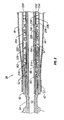
- the elastic anti-rotation members 46, 48 and the tool collar 40 may be provided with hydraulic piston and cylinder type linear voltage differential transformer (LVDT) assemblies, as shown generally at 50 and 51 in Fig. 4, which measure displacement hydraulic fluid as the anti-rotation members move radially inwardly and outwardly as the tool collar becomes temporarily offset from the centerline of the borehole, and which generate position signals that are electronically processed and utilized for steering during drilling. These position signals are used to provide a caliper measurement by measuring the axial displacement of each of the elastic anti-rotation members.
- LVDT linear voltage differential transformer
- a rotary drive shaft 54 which may be the output shaft of a mud motor, such as shown at 32 in Fig. 2, a drive connection sub driven by the output shaft of a mud motor, a drive connection of a rotary drill string, or any other suitable rotary drive means, extends into the tool collar 40 and is rotatable for the purpose of imparting driving force to an offsetting mandrel 56 which will be described in greater detail below.
- the rotary drive shaft 54 rotates within the tool collar 40 while the tool collar is restrained from rotation at the same rotary speed as the rotary drive shaft 54 by the coupled, frictionally sliding relationship of the elastic anti-rotation members 46 and 48 with the borehole wall.
- the rotary drive shaft 54 is sealed with respect to the tool collar 40 by seal or packing assembly 57.
- the seal or packing assembly 57 cooperates with rotary drive shaft 54 and tool collar 40 to define the uphole end of internal oil chamber 60 which is isolated at its downhole end by seal or packing assembly 58 from the drilling fluid flowing into the tool through rotary drive shaft 54.
- Oil chamber 60 contains a quantity of oil or other lubricating and protective fluid medium.
- Seal or packing assembly 58 also functions to isolate pressurized hydraulic fluid from internal oil chamber 60.
- the rotary drive shaft 54 defines an internal flow passage 62 through which drilling fluid flows en route to the drill bit 12.
- the rotary drive shaft 54 mates with an elongate rotary drive mandrel 64 which is fixed to the rotary drive shaft 54, such as by threaded connection, and also defines an internal bore 66 forming a part of the drilling fluid flow passage through the drilling tool.
- the elongate rotary drive mandrel 64 cooperates with the tool collar 40 to define a bearing chamber having thrust shoulders and receiving the bearings 52 so that axially and radially oriented thrust forces between the rotary drive mandrel 64 and the tool collar 40 will be accommodated during drilling operations.
- the rotary drive mandrel 64 is provided with a lower tubular drive section 68 about which the seal or packing assembly 58 is received and which defines a terminal drive connection 70 having an articulated driving connection with a drive sleeve 74.
- a plurality of spherical drive elements 76 are interposed between the terminal drive connection 70 and the upper end of the drive sleeve 74 and are seated within drive receptacles that are cooperatively defined by the terminal drive connection 70 and the upper end of the drive sleeve 74.
- the rotary drive mandrel 64 and its lower tubular drive section 68 are maintained in co-axial relation with the tool collar 40 by the bearings 52, while the drive sleeve 74 is permitted to articulate and yet maintain its driving connection with offsetting mandrel 56.
- the lower end of drive sleeve 74 is essentially a duplicate of the upper end thereof.
- Spherical drive elements 78 captured within drive receptacles cooperatively defined by the lower end of the drive sleeve 74 and the upper driven connection 80 of offsetting mandrel 56 provide a direct driving connection between drive sleeve 74 and offsetting mandrel 56, while at the same time permitting relative articulation between the drive sleeve and the offsetting mandrel.
- a one-piece mandrel with a flexible portion therein may be employed in place of the rotary drive mandrel 64, the articulated driving connection, and the offsetting mandrel 56.
- the offsetting mandrel 56 is mounted for rotation within tool collar 40 for omnidirectional movement about a pivot-like knuckle joint 82 which may be of the ball pivot configuration and function shown in Fig. 4 and described below.
- knuckle joint 82 may be of splined configuration or of any other suitable configuration that will permit omnidirectional movement of offsetting mandrel 56 and, during rotary driving thereof, will permit the offsetting mandrel 56 to be oriented within tool collar 40 to maintain its axis in geostationary relation with the formation being drilled.
- knuckle joint 82 of offsetting mandrel 56 with respect to tool collar 40 is defined by a spherical element 84 which is integral with or fixed to offsetting mandrel 56.
- Spherical element 84 defines an external spherical surface 86 which is received within a mandrel support receptacle 88 which is defined within the lower end 90 of the tool collar 40.
- the mandrel support receptacle 88 defines an internal spherical support surface segment having mating relation with the external spherical surface 86 of the spherical knuckle element 84.
- the offsetting mandrel 56 is therefore permitted to pivot relative to the lower end 90 of the tool collar 40 about an imaginary pivot point P, while simultaneously being rotated for driving of the drill bit 12 by the rotary driving connection that is established between the lower tubular drive section 68 of rotary drive mandrel 64 and drive sleeve 74.
- the pivotal movement of offsetting mandrel 56 about pivot point P, while its rotational driving connection is maintained, is permitted by the articulating driving connection that is established at each end of the drive sleeve 74 by the respective spherical drive elements 76 and 78.
- a yieldable bellows seal element 94 establishes sealed connection with the lower tubular drive section 68 of rotary drive mandrel 64 and the upper end of offsetting mandrel 56.
- another bellows seal element 96 is connected in sealed relation with the lower end of tool collar 40 and is also connected to a circular seal retainer element 98 that is located about a cylindrical section 100 of offsetting mandrel 56 and is provided with a circular sealing element 102 which is located within an internal seal groove of the circular seal retainer element 98.
- circular seal retainer element 98 remains in non-rotatable relation with respect to tool collar 40 and sealing element 102 maintains sealing engagement with the cylindrical section 100 of offsetting mandrel 56.
- the flexible bellows seal element 96 maintains a seal between tool collar 40 and seal retainer element 98 and prevents drilling fluid intrusion into the internal oil chamber 61.
- geostationary axial positioning of offsetting mandrel 56 is established hydraulically under the control of solenoid valves that are selectively actuated in response to appropriate position sensing signals.
- hydraulic pressure induced energy for controlling the position of offsetting mandrel 56 is generated by a hydraulic pump 104 which is located within a pump receptacle defined within tool collar 40.
- the pump drive shaft 110 is supported by appropriate bearings 106.
- Hydraulic pump 104 is driven by a rotary drive mechanism 108 responsive to rotation of the rotary drive mandrel 64 relative to tool collar 40.
- the rotary drive mechanism 108 may be coupled for driven rotation by the lower tubular drive section 68 of rotary drive mandrel 64 and may incorporate an internal gear train or transmission to establish a desired rotational relationship of the tubular drive section 68 with pump drive shaft 110 for imparting appropriate rotation and torque to the drive mechanism of hydraulic pump 104 to thus provide the pump with appropriate hydraulic pressure output and volume for accomplishing appropriate movement of offsetting mandrel 56 as the mandrel is rotated.
- the hydraulic fluid output of hydraulic pump 104 is conducted to a fluid passage 112 that is in communication with an annular hydraulic fluid chamber 114 having an annular piston 116 therein which is sealed to internal and external cylindrical walls 118 and 120 of hydraulic fluid chamber 114 by means of internal and external circular sealing elements 124 and 126 which are carried within respective seal grooves of the piston 116.
- the piston 116 is urged toward hydraulic pump 104 by one or more compression springs 128 which react against a fixed annular manifold block 130 having a plurality of valves therein.
- annular manifold block 130 The arrangement of annular manifold block 130 is illustrated schematically in Fig. 5.
- a return check valve 132 a spring-urged ball check valve, controls the return of pressurized hydraulic fluid to an annular hydraulic fluid accumulator chamber 134 which feeds hydraulic pump 104.
- a pair of solenoid actuated valves 140 and 142 control admission of pressurized hydraulic fluid to hydraulic fluid supply passages 144 and 146, respectively.
- the supply passages 144 and 146 supply pressurized hydraulic fluid to hydraulic cylinders 148 and 150, respectively, for actuation of hydraulic pistons 152 and 154.
- the hydraulic pistons 152 and 154 act through bearings or other contact members 156 to impart positioning force to offsetting mandrel 56.
- the pistons 152 and 154 are independently movable responsive to position signal controlled actuation of the solenoid valves 140 and 142 for pivoting of offsetting mandrel 56 about its pivot point P so that offsetting mandrel 56 is oriented by the effect of the pistons.
- the relative positions of the offsetting mandrel actuating pistons 152 and 154 are also determined by sensing means and controlled by the solenoid actuated valves 140 and 142 for the purpose of maintaining the longitudinal axis A of offsetting mandrel 56 in geostationary relation with respect to the formation being drilled and oriented at specific angles of inclination and azimuth to accomplish drilling of a curved wellbore along a predetermined path for drilling to a subsurface target.
- the rotary steerable drilling tool of the present invention is provided with an electronics and sensor package shown generally at 160.
- the electronics and sensor package incorporates a control loop which includes a three-axis accelerometer 162 to measure the orientation of the tool collar 40 relative to the gravity field.
- the cylinder and piston assemblies are provided with a pair of LVDT's 164 and 166 which function to measure the displacement of the pistons 152 and 154 as they are moved either by hydraulic pressure responsive to actuation of the solenoid actuated valves 140 and 142 or by spring energized return such as by return members 168 and 170 having compression springs 172 and 174 which provide a spring energized reaction force through the return members 168 and 170 via a mandrel positioning element 176 that is in force transmitting engagement with the offsetting mandrel 56 through the plurality of bearings or contact members 156 that accommodate rotation and pivotal articulation of offsetting mandrel 56 while at the same time permitting positioning actuation of offsetting mandrel 56.
- the LVDT's 164 and 166 measure the positions of each of the hydraulic pistons 152 and 154 relative to the tool collar 40 and transmit these measurement signals via signal conductors 180 and 182 to a controller 184. Signals from the three-axis accelerometer 162 are also conducted via a signal conductor 186 to the controller 184.
- an alternator 188 shown in Fig. 4, having an alternator drive coupling or transmission 190 that is driven by the rotary drive mandrel 64 via the lower tubular drive section 68 thereof.
- the alternator drive coupling 190 has an output shaft 192 that is supported within the tool collar 40 by a bearing 194 and is disposed in driving connection with the alternator 188.
- the drive coupling or transmission 190 may be of any suitable character, such as a gear train or belt drive, for example.
- the controller 184 provides control signal outputs for solenoid operation via a signal conductor 196 for controlling actuation of solenoid actuated valve 140 and a control signal output via signal conductor 198 for controlling actuation of solenoid actuated valve 142.
- the solenoid actuated valves 140 and 142 are actuated responsive to control signals from the controller 184 responsive to signal input from the LVDT's 164 and 166 and the accelerometer 162.
- the signals from LVDT's 164 and 166 identify controlled deviation of the axis of offsetting mandrel 56 along X and Y axes; thus, the hydraulic pistons 152 and 154 control the orientation of the axis A of offsetting mandrel 56 within tool collar 40 responsive to control of the solenoid actuated valves 140 and 142 for hydraulically energizing the pistons.
- Pressure control to the hydraulic cylinders 148 and 150 is established by pressure relief valves 210 and 212.
- tool collar 40 is shown to define an internal annular cavity 214 within which various electronics, control and sensor systems are located.
- This cavity is isolated from the protective oil medium by an isolation sleeve 216 having its ends sealed with respect to tool collar 40 by means of circular sealing elements 218 that are received within respective seal grooves defined within end portions of the isolation sleeve 216.
- Various electronic components such as a telemetry package 220, central processing unit 222, and a data acquisition package 224 are located within the internal annular cavity 214.
- a capacitor bank 226 may also be located within the cavity 214 to provide sufficient stored electrical energy for actuation of the solenoids of the solenoid valves and for accomplishing other control features that are appropriate for steering control of the rotary steerable drilling tool.
- the internal oil chamber 228 which is isolated from the environmental medium externally of tool collar 40 by a free piston 230 having sealed relation with internal and external cylindrical surfaces 232 and 234 by a circular sealing element 236.
- the internal oil chamber 228 is balanced with the pressure of the environmental medium by communicating environmental pressure through a vent port 238 to the environmental side 240 of the chamber.
- the pressure of the protective oil medium within the internal oil chamber 228 is pressure balanced with respect to environmental pressure regardless of the location of the drilling tool within the well.
Landscapes
- Engineering & Computer Science (AREA)
- Life Sciences & Earth Sciences (AREA)
- Geology (AREA)
- Mining & Mineral Resources (AREA)
- Physics & Mathematics (AREA)
- Environmental & Geological Engineering (AREA)
- Fluid Mechanics (AREA)
- General Life Sciences & Earth Sciences (AREA)
- Geochemistry & Mineralogy (AREA)
- Geophysics (AREA)
- Mechanical Engineering (AREA)
- Earth Drilling (AREA)
Claims (24)
- Verfahren zum Bohren von Bohrlöchern und zum gleichzeitigen Lenken einer Bohrkrone mit einem rotierenden lenkbaren Bohrsystem, wobei das Verfahren umfaßt:(a) in dem Bohrloch, das gebohrt wird, Drehen einer Antriebskomponente (54) innerhalb eines Schubwerkzeugkranzes (40), wobei die Antriebskomponente in Bezug auf einen Verstelldorn (56), der in dem Schubwerkzeugkranz schwenkbar angebracht ist und eine Bohrkrone (12) unterstützt, rotatorisch angetrieben wird;(b) gleitendes Bewegen des Schubwerkzeugkranzes (40) in gekoppelter Beziehung zu der Bohrlochwand während des Bohrens; und(c) Bereitstellen von Lenkungsteuersignalen;
dadurch gekennzeichnet, daß das Lenken der Bohrkrone (12) durch die Steuersignale aktiv gesteuert wird; und(d) der Verstelldorn (56) in Reaktion auf die Lenkungsteuersignale während seiner Antriebsdrehung durch die Drehantriebskomponente (54) um seine Schwenkhalterung (82) hydraulisch positioniert wird, um die Achse des Verstelldoms im Wesentlichen geostationär bei wählbaren Neigungs- und Peilungswinkeln zu halten. - Verfahren nach Anspruch 1, bei dem der Schubwerkzeugkranz (40) äußere elastische Elemente (46, 48) besitzt, die hiervon im Wesentlichen radial nach außen vorstehen, wobei das Verfahren ferner umfaßt:(e) Aufrechterhalten eines Gleitkontakts zwischen den äußeren elastischen Elementen (46, 48) und der Bohrlochwand während des Bohrens, um eine Drehung des Werkzeugkranzes in dem Bohrloch während des Bohrens im Wesentlichen zu verhindern.
- Verfahren nach Anspruch 1, bei dem der Schubwerkzeugkranz (40) geräteseitige Systeme (104, 188), die einen Hydraulikfluiddruck und elektrische Energie erzeugen, und Hydraulikkolbenmittel (152, 154), die für den Verstelldorn (56) in Bezug auf den Schubwerkzeugkranz während der Drehung des Verstelldorns durch die Drehantriebskomponente eine Positionssteuerung schaffen, umfaßt, wobei die geräteseitigen Systeme elektrisch gesteuerte Ventilmittel (140, 142) besitzen, die eine durch den Hydraulikdruck hervorgerufene Bewegung der Hydraulikkolbenmittel steuern, wobei das Verfahren ferner umfaßt:(e) Erzeugen eines Hydraulikdrucks und elektrischer Energie in Reaktion auf die Bohrfluidströmung; und(f) elektrisches Betätigen der elektrisch gesteuerten Ventilmittel (140, 142) in Reaktion auf die Lenkungssignale, um die Übertragung des Hydraulikdrucks an die Hydraulikkolbenmittel (152, 154) zu steuern, um eine hydraulische Positionierung des Verstelldorns (56) zu bewirken.
- Verfahren nach Anspruch 3, bei dem die Kolbenmittel (152, 154) wenigstens zwei Kolben (152 und 154) umfassen, wovon jeder zwischen den Schubwerkzeugkranz (40) und den Verstelldorn (56) eingefügt ist und mit diesen in einer Kraftübertragungsbeziehung steht, wobei das Verfahren ferner umfaßt:(g) wahlweises und unabhängig steuerbares Erhöhen und Erniedrigen des auf jeden der Kolben wirkenden Hydraulikdrucks, um die kolbenbetätigte Schwenkpositionierung des Verstelldorns in dem Schubwerkzeugkranz zu bewirken.
- Verfahren nach Anspruch 4, bei dem die Hydraulikkolbenmittel (152, 154) in Hydraulikzylindermitteln (148, 150) beweglich angeordnet sind, wobei das Verfahren ferner umfaßt:(h) Erfassen der jeweiligen Positionen der Kolbenmittel in den Zylindermitteln und Herstellen einer Beziehung zwischen den jeweiligen Positionen der Kolbenmittel und den Schwenkpositionen des Verstelldorns (56) in dem Schubwerkzeugkranz (40);(i) Identifizieren der jeweiligen Positionsänderung der Kolbenmittel für eine gewünschte Schwenkpositionsänderung des Verstelldorns; und(j) gesteuertes Betätigen der elektrisch gesteuerten Ventilmittel (140, 142), um die Hydraulikdruckverbindung mit den Zylindermitteln unabhängig zu steuern, um die gewünschte Positionsänderung der Kolbenmittel zu erzielen.
- Verfahren nach Anspruch 5, das ferner umfaßt:(k) Erfassen des Volumens des Hydraulikfluids in den Hydraulikzylindermitteln (148, 150), um die Kolbenposition in den Hydraulikzylindermitteln zu identifizieren;(l) Ändern des Volumens des Hydraulikfluids in den Hydraulikzylindermitteln, um dadurch die Kolbenposition zu ändern und dadurch die Position des Verstelldorns (56) in dem Schubwerkzeugkranz (40) zu ändern; und(m) aufeinander folgendes Ändern der Position des Verstelldorns in dem Schubwerkzeugkranz, um dadurch den Verstelldorn während seiner Drehung durch die Drehantriebskomponente in einer im Wesentlichen geostationären Beziehung und in einer in Bezug auf Azimut und Neigung bestimmten Orientierung zu halten.
- Verfahren nach Anspruch 1, bei dem das Bereitstellen von Lenkungsteuersignalen umfaßt:(a) Erfassen des Ortes und der Orientierung des Werkzeugkranzes und der Winkelposition des Verstelldorns in Bezug auf den Schubwerkzeugkranz und Erzeugen von Echtzeit-Positionssignalen;(b) Verarbeiten der Echtzeit-Positionssignale und Erzeugen der Lenkungsteuersignale; und(c) Steuern der Positionierung des Verstelldorns mit den Lenkungsteuersignalen.
- Verfahren nach Anspruch 1, bei dem das rotierende lenkbare Bohrsystem geräteseitige Elektronik zum Empfangen von Lenkungsteuersignalen umfaßt, wobei das Verfahren ferner umfaßt:(e) Übertragen von Lenkungsteuersignalen von einem Ort an der Oberfläche an die geräteseitige Elektronik; und(f) Steuern der Positionierung des Verstelldorns mit den Lenkungsteuersignalen.
- Verfahren nach Anspruch 1, bei dem der Schubwerkzeugkranz (40) wenigstens zwei in ihm ausgebildete Hydraulikzylinder (148, 150), wovon jeder einen in einem Positionierungseingriff mit dem Verstelldom (56) angeordneten Hydraulikkolben (152, 154) besitzt, eine Versorgung (104) für mit Druck beaufschlagtes Hydraulikfluid für die Hydraulikzylinder sowie elektrisch gesteuerte Hydraulikfluid-Steuerventilmittel (140, 142) für die wahlweise Herstellung einer Verbindung für mit Druck beaufschlagtes Hydraulikfluid zu den Hydraulikzylindern besitzt und ferner eine elektronische Steuereinheit (184) besitzt, die Positionssignale empfängt und wahlweise die elektrisch gesteuerten Hydraulikfluid-Steuerventilmittel betätigt, um den Verstelldorn in Bezug auf den Schubwerkzeugkranz hydraulisch gesteuert zu positionieren, wobei das Verfahren ferner umfaßt:(e) Erzeugen elektronischer Kolbenpositionssignale, die die Positionen der Hydraulikkolben in den Hydraulikzylindern repräsentieren;(f) Bereitstellen elektronischer Werkzeugkranz-Positionssignale, die die Position des Schubwerkzeugkranzes repräsentieren; und(g) Verarbeiten der elektronischen Kolbenpositionssignale und der elektronischen Werkzeugkranzpositionssignale durch die Steuereinheit und Bereitstellen von Ventilpositionsausgangssignalen von der Steuereinheit, um die Position der Hydraulikfluid-Steuerventilmittel gegebenenfalls zu ändern, um die Position des Verstelldorns in Bezug auf den Schubwerkzeugkranz zu ändern.
- Rotierendes steuerbares Bohrloch-Bohrsystem, das umfaßt:(a) einen Schubwerkzeugkranz (40);(b) Mittel (46, 48), die eine Kopplung des Schubwerkzeugkranzes mit der Wand des Bohrlochs, das gebohrt wird, aufrechterhalten und eine Drehung des Schubwerkzeugkranzes während des Bohrens im Wesentlichen verhindern;(c) einen Verstelldorn (56), der in dem Schubwerkzeugkranz so angebracht ist, daß er relativ zu dem Schubwerkzeugkranz eine Schwenkbewegung ausführen und sich relativ zu dem Schubwerkzeugkranz drehen kann, wobei der Verstelldorn eine Bohrkrone (12) trägt;(d) Mittel (54, 64), die den Verstelldorn mit einer Antriebsdrehung beaufschlagen; und(e) Mittel (184) zum Erzeugen von Lenkungsteuersignalen;
wobei das System dadurch gekennzeichnet ist, daß die Bohrkrone (12) aktiv steuerbar ist durch:(f) Hydraulikaktuatormittel (104, 140, 142, 152, 154), die in Reaktion auf die Lenkungsteuersignale die Achse des Verstelldorns (56) unter wählbaren Neigungs- und Peilungswinkeln im Wesentlichen geostationär halten. - Rotierendes lenkbares Bohrsystem nach Anspruch 10, bei dem die Hydraulikaktuatormittel (104,140, 142, 148, 150, 152, 154) umfassen:(a) Hydraulikzylindermittel (148, 150) in dem Schubwerkzeugkranz (40);(b) Hydraulikkolbenmittel (152, 154), die mit dem Verstelldorn in einer Kraftübertragungsbeziehung stehen, in den Hydraulikzylindermitteln;(c) Mittel (104), die mit Druck beaufschlagtes Hydraulikfluid an die Hydraulikzylindermittel liefern, um eine Schwenkbewegung des Verstelldorns zur Positionsaufrechterhaltung in dem Schubwerkzeugkranz zu bewerkstelligen; und(d) Mittel (140, 142), die in Reaktion auf Positionierungssignale die Mittel zum Liefern des mit Druck beaufschlagten Hydraulikfluids steuerbar betätigen und somit den Verstelldorn (56) an einer ausgewählten Position in Bezug auf den Schubwerkzeugkranz (40) halten.
- Rotierendes lenkbares Bohrloch-Bohrsystem nach Anspruch 10, bei dem die Mittel (46, 48) für die Aufrechterhaltung der Kopplung des Schubwerkzeugkranzes (40) mit der Wand des Bohrlochs, das gebohrt wird, elastische Kopplungsmittel (46, 48) umfassen, die durch den Schubwerkzeugkranz unterstützt sind und hiervon ausreichend weit radial vorstehen, um mit der Wand des Bohrlochs in einen zwangsläufigen Eingriff zu gelangen.
- Rotierendes lenkbares Bohrloch-Bohrsystem nach Anspruch 12, bei dem die elastischen Kopplungsmittel (46, 48) mehrere elastische Kopplungselemente umfassen, die sich in einer beabstandeten Beziehung um den Schubwerkzeugkranz (40) befinden, und ferner Mittel (50, 51) umfassen, die die relativen Positionen der elastischen Kopplungsmittel in Bezug auf den Schubwerkzeugkranz erfassen und elektronische Signale erzeugen, die die relativen Positionen und somit eine Messung des Durchmessers des Bohrlochs, das gebohrt wird, repräsentieren.
- Rotierendes lenkbares Bohrloch-Bohrsystem nach Anspruch 10, bei dem die Mittel (46, 48) für die Aufrechterhaltung der Kopplung des Schubwerkzeugkranzes mit der Wand des Bohrlochs, das gebohrt wird, mehrere lang gestreckte elastische Flügel (46, 48) umfassen, wovon wenigstens ein Ende mit dem Schubwerkzeugkranz verbunden ist, wobei die mehreren lang gestreckten elastischen Flügel von dem Schubwerkzeugkranz radial nach außen vorstehen, um in einen zwangsläufigen Kopplungseingriff mit der Wand des Bohrlochs zu gelangen.
- Rotierendes lenkbares Bohrloch-Bohrsystem nach Anspruch 10, bei dem die Mittel (46, 48) zum Aufrechterhalten der Kopplung des Schubwerkzeugkranzes mit der Wand des gebohrten Bohrlochs mehrere lang gestreckte, gekrümmte elastische Flügel (46, 48) umfassen, wovon jeder Enden und einen Mittelabschnitt besitzt, wobei die Enden mit dem Schubwerkzeugkranz verbunden sind und die Mittelabschnitte jedes der mehreren lang gestreckten elastischen Flügel von dem Schubwerkzeugkranz radial nach außen vorstehen, um einen zwangsläufigen Kopplungseingriff mit der Wand des Bohrlochs zu schaffen.
- Rotierendes lenkbares Bohrloch-Bohrsystem nach Anspruch 10, das ferner umfaßt:(g) ein Universalgelenk (82) in dem Schubwerkzeugkranz (40); wobei der Verstelldorn (56) durch das Universalgelenk schwenkbar und rotatorisch unterstützt wird, wodurch sowohl eine rotierende Bewegung als auch eine omnidirektionale Schwenkbewegung des Verstelldoms in Bezug auf den Schubwerkzeugkranz ermöglicht wird.
- Rotierendes lenkbares Bohrloch-Bohrsystem nach Anspruch 10, bei dem die Mittel (54, 64), die den Verstelldorn (56) mit einer Antriebsdrehung beaufschlagen, umfassen:(a) eine röhrenförmige Drehantriebswelle (54, 64), die einen Strömungsdurchlass (62, 66) definiert, sich in dem Schubwerkzeugkranz (40) befindet, ein für eine Verbindung mit einem Drehantriebselement ausgelegtes angetriebenes Ende besitzt und ein Antriebsende besitzt;(b) Lagermittel (52), die die röhrenförmige Drehantriebswelle in dem Schubwerkzeugkranz unterstützen; und(c) Mittel (70), die eine gelenkige Antriebsverbindung zwischen dem Antriebsende der röhrenförmigen Drehantriebswelle und dem Verstelldorn herstellen.
- Rotierendes lenkbares Bohrloch-Bohrsystem nach Anspruch 17, bei dem der Verstelldorn (56) einen Strömungsdurchlass (92) für die Strömung von Bohrfluid hindurch definiert; und das ferner umfaßt:(f) Kranzdichtungsmittel (96), die eine abgedichtete Trennwand zwischen dem Schubwerkzeugkranz (40) und dem Verstelldorn (56) bilden und eine Schutzfluidkammer definieren, die ein Schutzfluidmedium enthält, wobei die Kranzdichtungsmittel die Kammer gegenüber einem Eindringen von Bohrfluid isolieren; und(g) Domdichtungsmittel (94), die Dichtungen mit dem Verstelldorn und mit dem Antriebsende der röhrenförmigen Drehantriebswelle (54, 64) schaffen und außerdem die Schutzfluidkammer vor einem Eindringen von Bohrfluid isolieren.
- Rotierendes lenkbares Bohrloch-Bohrsystem nach Anspruch 10, das ferner umfaßt:(f) ein Hydraulikfluid-Versorgungssystem (104), das sich in dem Schubwerkzeugkranz (40) befindet und durch die Drehung der Antriebsmittel (54, 64) während des Bohrens mit Leistung versorgt wird, wobei das Hydraulikfluid-Versorgungssystem mit Druck beaufschlagtes Hydraulikfluid an die Hydraulikaktuatormittel (148, 150, 152, 154) liefert;(g) ein Versorgungssystem (188) für elektrische Leistung, das sich in dem Schubwerkzeugkranz befindet und durch die Drehung der Antriebsmittel während des Bohrens mit Leistung versorgt wird; und(h) elektrisch betätigte Ventilmittel (140, 142), die in das Hydraulikfluid-Versorgungssystem eingebaut sind und die Lieferung von mit Druck beaufschlagtem Hydraulikfluid an die Hydraulikaktuatormittel steuern.
- Rotierendes lenkbares Bohrloch-Bohrsystem nach Anspruch 19, das ferner umfaßt:(i) Positionserfassungsmittel (162), die sich in dem Schubwerkzeugkranz (40) befinden und die Position des Schubwerkzeugkranzes in der durchbohrten Formation erfassen und Positionssignale bereitstellen; und(j) Steuermittel (184), die sich in dem Schubwerkzeugkranz befinden und die Positionssignale empfangen, wobei die Steuermittel Ventilsteuerungs-Ausgangssignale zum wahlweisen Steuern des Betriebs der elektrisch betätigten Ventilmittel (140, 142) bereitstellen.
- Rotierendes lenkbares Bohrloch-Bohrsystem nach Anspruch 10, das ferner umfaßt:(f) Hydraulikfluid-Versorgungsmittel (104), die sich in dem Schubwerkzeugkranz (40) befinden;(g) Versorgungsmittel (188) für elektrische Leistung, die sich in dem Schubwerkzeugkranz befinden;(h) elektrisch betätigte Ventilmittel (140, 142), die in die Hydraulikfluid-Versorgungsmittel eingebaut sind und die Lieferung von mit Druck beaufschlagtem Hydraulikfluid an die Hydraulikaktuatormittel (148, 150, 152, 154) steuern;(i) Positionserfassungsmittel (164, 166), die die Position der Hydraulikaktuatormittel erfassen und einen Positionssignalausgang bereitstellen; und(j) Steuermittel (184), die den Positionssignalausgang empfangen und verarbeiten und Steuersignale zum wahlweisen Steuern der Betätigung der elektrisch betätigten Ventilmittel bereitstellen.
- Rotierendes lenkbares Bohrloch-Bohrsystem nach Anspruch 21, das ferner umfaßt:(k) Telemetriemittel (220), die sich in dem Schubwerkzeugkranz (40) befinden und Positionssteuersignale empfangen, die von der Oberfläche übertragen werden, und einen Telemetriesignalausgang bereitstellen; wobei die Steuermittel (184) den Telemetriesignalausgang empfangen und verarbeiten.
- Rotierendes lenkbares Bohrloch-Bohrsystem nach Anspruch 21, das ferner umfaßt:(k) wenigstens einen Beschleunigungsmesser (162), der sich in dem Schubwerkzeugkranz (40) befindet, um Positionsänderungen des Schubwerkzeugkranzes zu erfassen und um in Reaktion darauf Positionssignale bereitzustellen; wobei die Steuermittel (184) die Positionssignale empfangen und verarbeiten.
- Rotierendes lenkbares Bohrloch-Bohrsystem nach Anspruch 10, bei dem:die Hydraulikaktuatormittel wenigstens zwei hydraulisch bewegbare Elemente umfassen, wovon jedes in einer Kraftübertragungsbeziehung zu dem Verstelldorn an von der Schwenkhalterung an dem Schubwerkzeugkranz entfernten Orten steht; und bei dem die hydraulisch bewegbaren Elemente bei ihrer Betätigung den Verstelldorn um die Schwenkhalterung bewegen, um seine wahlweise Positionierung in Bezug auf den Schubwerkzeugkranz aufrechtzuerhalten.
Applications Claiming Priority (2)
| Application Number | Priority Date | Filing Date | Title |
|---|---|---|---|
| US210520 | 1994-03-18 | ||
| US09/210,520 US6158529A (en) | 1998-12-11 | 1998-12-11 | Rotary steerable well drilling system utilizing sliding sleeve |
Publications (2)
| Publication Number | Publication Date |
|---|---|
| EP1008717A1 EP1008717A1 (de) | 2000-06-14 |
| EP1008717B1 true EP1008717B1 (de) | 2004-10-27 |
Family
ID=22783234
Family Applications (1)
| Application Number | Title | Priority Date | Filing Date |
|---|---|---|---|
| EP99204163A Expired - Lifetime EP1008717B1 (de) | 1998-12-11 | 1999-12-06 | Dreh- und steuerbares Bohrsystem mit Schiebehülse |
Country Status (11)
| Country | Link |
|---|---|
| US (1) | US6158529A (de) |
| EP (1) | EP1008717B1 (de) |
| CN (1) | CN1222677C (de) |
| AU (1) | AU745767B2 (de) |
| BR (1) | BR9905828A (de) |
| CA (1) | CA2291922C (de) |
| DE (1) | DE69921429D1 (de) |
| GC (1) | GC0000115A (de) |
| ID (1) | ID24512A (de) |
| NO (1) | NO314196B1 (de) |
| RU (1) | RU2229012C2 (de) |
Families Citing this family (262)
| Publication number | Priority date | Publication date | Assignee | Title |
|---|---|---|---|---|
| US6340063B1 (en) | 1998-01-21 | 2002-01-22 | Halliburton Energy Services, Inc. | Steerable rotary directional drilling method |
| US6470974B1 (en) | 1999-04-14 | 2002-10-29 | Western Well Tool, Inc. | Three-dimensional steering tool for controlled downhole extended-reach directional drilling |
| US6467557B1 (en) * | 1998-12-18 | 2002-10-22 | Western Well Tool, Inc. | Long reach rotary drilling assembly |
| NO309491B1 (no) * | 1999-06-24 | 2001-02-05 | Bakke Technology As | Anordning ved verktöy tilpasset for å endre boreretningen under boring |
| US6948572B2 (en) * | 1999-07-12 | 2005-09-27 | Halliburton Energy Services, Inc. | Command method for a steerable rotary drilling device |
| US6308787B1 (en) * | 1999-09-24 | 2001-10-30 | Vermeer Manufacturing Company | Real-time control system and method for controlling an underground boring machine |
| US6257356B1 (en) * | 1999-10-06 | 2001-07-10 | Aps Technology, Inc. | Magnetorheological fluid apparatus, especially adapted for use in a steerable drill string, and a method of using same |
| US6427783B2 (en) * | 2000-01-12 | 2002-08-06 | Baker Hughes Incorporated | Steerable modular drilling assembly |
| US6419014B1 (en) * | 2000-07-20 | 2002-07-16 | Schlumberger Technology Corporation | Apparatus and method for orienting a downhole tool |
| GB0026315D0 (en) | 2000-10-27 | 2000-12-13 | Antech Ltd | Directional drilling |
| FR2817903B1 (fr) * | 2000-12-07 | 2003-04-18 | Inst Francais Du Petrole | Dispositif de forage directionnel rotary comportant un moyen de flexion stabilise |
| FR2817904B1 (fr) * | 2000-12-07 | 2003-04-18 | Inst Francais Du Petrole | Dispositif de forage directionnel rotary comportant un moyen de flexion a nacelle |
| FR2817905B1 (fr) * | 2000-12-07 | 2003-01-10 | Inst Francais Du Petrole | Dispositif de forage directionnel rotary comportant un moyen de flexion a glissieres |
| US6467341B1 (en) | 2001-04-24 | 2002-10-22 | Schlumberger Technology Corporation | Accelerometer caliper while drilling |
| US6840336B2 (en) | 2001-06-05 | 2005-01-11 | Schlumberger Technology Corporation | Drilling tool with non-rotating sleeve |
| US6837315B2 (en) * | 2001-05-09 | 2005-01-04 | Schlumberger Technology Corporation | Rotary steerable drilling tool |
| US6571888B2 (en) | 2001-05-14 | 2003-06-03 | Precision Drilling Technology Services Group, Inc. | Apparatus and method for directional drilling with coiled tubing |
| CA2494237C (en) * | 2001-06-28 | 2008-03-25 | Halliburton Energy Services, Inc. | Drill tool shaft-to-housing locking device |
| AR034780A1 (es) * | 2001-07-16 | 2004-03-17 | Shell Int Research | Montaje de broca giratoria y metodo para perforacion direccional |
| US7188685B2 (en) * | 2001-12-19 | 2007-03-13 | Schlumberge Technology Corporation | Hybrid rotary steerable system |
| US6810971B1 (en) | 2002-02-08 | 2004-11-02 | Hard Rock Drilling & Fabrication, L.L.C. | Steerable horizontal subterranean drill bit |
| US6814168B2 (en) | 2002-02-08 | 2004-11-09 | Hard Rock Drilling & Fabrication, L.L.C. | Steerable horizontal subterranean drill bit having elevated wear protector receptacles |
| US6827159B2 (en) | 2002-02-08 | 2004-12-07 | Hard Rock Drilling & Fabrication, L.L.C. | Steerable horizontal subterranean drill bit having an offset drilling fluid seal |
| US6810973B2 (en) | 2002-02-08 | 2004-11-02 | Hard Rock Drilling & Fabrication, L.L.C. | Steerable horizontal subterranean drill bit having offset cutting tooth paths |
| US6810972B2 (en) | 2002-02-08 | 2004-11-02 | Hard Rock Drilling & Fabrication, L.L.C. | Steerable horizontal subterranean drill bit having a one bolt attachment system |
| US6742604B2 (en) | 2002-03-29 | 2004-06-01 | Schlumberger Technology Corporation | Rotary control of rotary steerables using servo-accelerometers |
| US7556105B2 (en) * | 2002-05-15 | 2009-07-07 | Baker Hughes Incorporated | Closed loop drilling assembly with electronics outside a non-rotating sleeve |
| DE10235700B3 (de) * | 2002-08-03 | 2004-01-22 | Deutsche Montan Technologie Gmbh | Richtbohrgerät |
| US6761232B2 (en) | 2002-11-11 | 2004-07-13 | Pathfinder Energy Services, Inc. | Sprung member and actuator for downhole tools |
| US7270198B2 (en) * | 2002-12-09 | 2007-09-18 | American Kinetics, Inc. | Orienter for drilling tool assembly and method |
| US7084782B2 (en) * | 2002-12-23 | 2006-08-01 | Halliburton Energy Services, Inc. | Drill string telemetry system and method |
| US6857484B1 (en) * | 2003-02-14 | 2005-02-22 | Noble Drilling Services Inc. | Steering tool power generating system and method |
| US6942043B2 (en) * | 2003-06-16 | 2005-09-13 | Baker Hughes Incorporated | Modular design for LWD/MWD collars |
| US7267184B2 (en) * | 2003-06-17 | 2007-09-11 | Noble Drilling Services Inc. | Modular housing for a rotary steerable tool |
| US20040256162A1 (en) * | 2003-06-17 | 2004-12-23 | Noble Drilling Services Inc. | Split housing for rotary steerable tool |
| EP1923534B1 (de) * | 2003-09-15 | 2010-11-10 | Baker Hughes Incorporated | Steuerbare Bohrmeißelanordnung und entsprechende Verfahren |
| US7287604B2 (en) * | 2003-09-15 | 2007-10-30 | Baker Hughes Incorporated | Steerable bit assembly and methods |
| CA2448723C (en) * | 2003-11-07 | 2008-05-13 | Halliburton Energy Services, Inc. | Variable gauge drilling apparatus and method of assembly thereof |
| GB2408526B (en) | 2003-11-26 | 2007-10-17 | Schlumberger Holdings | Steerable drilling system |
| US7243739B2 (en) * | 2004-03-11 | 2007-07-17 | Rankin Iii Robert E | Coiled tubing directional drilling apparatus |
| GB2415972A (en) * | 2004-07-09 | 2006-01-11 | Halliburton Energy Serv Inc | Closed loop steerable drilling tool |
| US7287605B2 (en) * | 2004-11-02 | 2007-10-30 | Scientific Drilling International | Steerable drilling apparatus having a differential displacement side-force exerting mechanism |
| US7669668B2 (en) * | 2004-12-01 | 2010-03-02 | Schlumberger Technology Corporation | System, apparatus, and method of conducting measurements of a borehole |
| US7204325B2 (en) * | 2005-02-18 | 2007-04-17 | Pathfinder Energy Services, Inc. | Spring mechanism for downhole steering tool blades |
| BE1016460A3 (fr) | 2005-02-21 | 2006-11-07 | Diamant Drilling Services Sa | Dispositif pour le suivi d'une operation de forage ou de carottage et installation comprenant un tel dispositif. |
| US7481282B2 (en) | 2005-05-13 | 2009-01-27 | Weatherford/Lamb, Inc. | Flow operated orienter |
| US7383897B2 (en) * | 2005-06-17 | 2008-06-10 | Pathfinder Energy Services, Inc. | Downhole steering tool having a non-rotating bendable section |
| GB0521693D0 (en) | 2005-10-25 | 2005-11-30 | Reedhycalog Uk Ltd | Representation of whirl in fixed cutter drill bits |
| US7584800B2 (en) * | 2005-11-09 | 2009-09-08 | Schlumberger Technology Corporation | System and method for indexing a tool in a well |
| US20070241670A1 (en) * | 2006-04-17 | 2007-10-18 | Battelle Memorial Institute | Organic materials with phosphine sulfide moieties having tunable electric and electroluminescent properties |
| US8590636B2 (en) * | 2006-04-28 | 2013-11-26 | Schlumberger Technology Corporation | Rotary steerable drilling system |
| US7607478B2 (en) * | 2006-04-28 | 2009-10-27 | Schlumberger Technology Corporation | Intervention tool with operational parameter sensors |
| CA2545377C (en) * | 2006-05-01 | 2011-06-14 | Halliburton Energy Services, Inc. | Downhole motor with a continuous conductive path |
| GB0610814D0 (en) * | 2006-06-01 | 2006-07-12 | Geolink Uk Ltd | Rotary steerable drilling tool |
| EP1857631A1 (de) * | 2006-05-19 | 2007-11-21 | Services Pétroliers Schlumberger | Vorrichtung zur Richtungskontrolle beim Bohren |
| WO2007143773A1 (en) | 2006-06-16 | 2007-12-21 | Harrofam Pty Ltd | Microtunnelling system and apparatus |
| WO2008004999A1 (en) * | 2006-06-30 | 2008-01-10 | Baker Hughes Incorporated | Closed loop drilling assembly with electronics outside a non-rotating sleeve |
| US7748466B2 (en) | 2006-09-14 | 2010-07-06 | Thrubit B.V. | Coiled tubing wellbore drilling and surveying using a through the drill bit apparatus |
| US7464770B2 (en) * | 2006-11-09 | 2008-12-16 | Pathfinder Energy Services, Inc. | Closed-loop control of hydraulic pressure in a downhole steering tool |
| US7967081B2 (en) * | 2006-11-09 | 2011-06-28 | Smith International, Inc. | Closed-loop physical caliper measurements and directional drilling method |
| US8118114B2 (en) * | 2006-11-09 | 2012-02-21 | Smith International Inc. | Closed-loop control of rotary steerable blades |
| US20080142268A1 (en) * | 2006-12-13 | 2008-06-19 | Geoffrey Downton | Rotary steerable drilling apparatus and method |
| US7377333B1 (en) | 2007-03-07 | 2008-05-27 | Pathfinder Energy Services, Inc. | Linear position sensor for downhole tools and method of use |
| FR2914419B1 (fr) * | 2007-03-30 | 2009-10-23 | Datc Europ Sa | Dispositif de protection d'une sonde geotechnique ou geophysique |
| US8497685B2 (en) | 2007-05-22 | 2013-07-30 | Schlumberger Technology Corporation | Angular position sensor for a downhole tool |
| US7725263B2 (en) * | 2007-05-22 | 2010-05-25 | Smith International, Inc. | Gravity azimuth measurement at a non-rotating housing |
| US7669669B2 (en) * | 2007-07-30 | 2010-03-02 | Schlumberger Technology Corporation | Tool face sensor method |
| US8534380B2 (en) * | 2007-08-15 | 2013-09-17 | Schlumberger Technology Corporation | System and method for directional drilling a borehole with a rotary drilling system |
| US8720604B2 (en) * | 2007-08-15 | 2014-05-13 | Schlumberger Technology Corporation | Method and system for steering a directional drilling system |
| US8727036B2 (en) * | 2007-08-15 | 2014-05-20 | Schlumberger Technology Corporation | System and method for drilling |
| US8757294B2 (en) * | 2007-08-15 | 2014-06-24 | Schlumberger Technology Corporation | System and method for controlling a drilling system for drilling a borehole in an earth formation |
| US8763726B2 (en) * | 2007-08-15 | 2014-07-01 | Schlumberger Technology Corporation | Drill bit gauge pad control |
| US20100038141A1 (en) * | 2007-08-15 | 2010-02-18 | Schlumberger Technology Corporation | Compliantly coupled gauge pad system with movable gauge pads |
| US8066085B2 (en) * | 2007-08-15 | 2011-11-29 | Schlumberger Technology Corporation | Stochastic bit noise control |
| US7588100B2 (en) * | 2007-09-06 | 2009-09-15 | Precision Drilling Corporation | Method and apparatus for directional drilling with variable drill string rotation |
| US7836975B2 (en) | 2007-10-24 | 2010-11-23 | Schlumberger Technology Corporation | Morphable bit |
| US8442769B2 (en) * | 2007-11-12 | 2013-05-14 | Schlumberger Technology Corporation | Method of determining and utilizing high fidelity wellbore trajectory |
| GB2455734B (en) | 2007-12-19 | 2010-03-24 | Schlumberger Holdings | Steerable system |
| RU2457310C2 (ru) * | 2007-12-19 | 2012-07-27 | Шлюмбергер Текнолоджи Б.В. | Направляющая система и система направленного бурения, содержащая указанную систему |
| GB0724900D0 (en) * | 2007-12-21 | 2008-01-30 | Schlumberger Holdings | Hybrid drilling system with mud motor |
| GB2456421B (en) | 2008-01-17 | 2012-02-22 | Weatherford Lamb | Flow operated orienter |
| US8813869B2 (en) * | 2008-03-20 | 2014-08-26 | Schlumberger Technology Corporation | Analysis refracted acoustic waves measured in a borehole |
| US8528662B2 (en) * | 2008-04-23 | 2013-09-10 | Amkin Technologies, Llc | Position indicator for drilling tool |
| US7779933B2 (en) * | 2008-04-30 | 2010-08-24 | Schlumberger Technology Corporation | Apparatus and method for steering a drill bit |
| US8714246B2 (en) | 2008-05-22 | 2014-05-06 | Schlumberger Technology Corporation | Downhole measurement of formation characteristics while drilling |
| US8061444B2 (en) | 2008-05-22 | 2011-11-22 | Schlumberger Technology Corporation | Methods and apparatus to form a well |
| WO2009142868A2 (en) | 2008-05-23 | 2009-11-26 | Schlumberger Canada Limited | Drilling wells in compartmentalized reservoirs |
| US7818128B2 (en) * | 2008-07-01 | 2010-10-19 | Schlumberger Technology Corporation | Forward models for gamma ray measurement analysis of subterranean formations |
| US8960329B2 (en) * | 2008-07-11 | 2015-02-24 | Schlumberger Technology Corporation | Steerable piloted drill bit, drill system, and method of drilling curved boreholes |
| US20100018770A1 (en) * | 2008-07-25 | 2010-01-28 | Moriarty Keith A | System and Method for Drilling a Borehole |
| US7971662B2 (en) | 2008-09-25 | 2011-07-05 | Baker Hughes Incorporated | Drill bit with adjustable steering pads |
| US9915138B2 (en) | 2008-09-25 | 2018-03-13 | Baker Hughes, A Ge Company, Llc | Drill bit with hydraulically adjustable axial pad for controlling torsional fluctuations |
| US8205686B2 (en) | 2008-09-25 | 2012-06-26 | Baker Hughes Incorporated | Drill bit with adjustable axial pad for controlling torsional fluctuations |
| US20100101867A1 (en) * | 2008-10-27 | 2010-04-29 | Olivier Sindt | Self-stabilized and anti-whirl drill bits and bottom-hole assemblies and systems for using the same |
| US7950473B2 (en) * | 2008-11-24 | 2011-05-31 | Smith International, Inc. | Non-azimuthal and azimuthal formation evaluation measurement in a slowly rotating housing |
| US7819666B2 (en) * | 2008-11-26 | 2010-10-26 | Schlumberger Technology Corporation | Rotating electrical connections and methods of using the same |
| US8146679B2 (en) * | 2008-11-26 | 2012-04-03 | Schlumberger Technology Corporation | Valve-controlled downhole motor |
| US8179278B2 (en) * | 2008-12-01 | 2012-05-15 | Schlumberger Technology Corporation | Downhole communication devices and methods of use |
| US8376366B2 (en) * | 2008-12-04 | 2013-02-19 | Schlumberger Technology Corporation | Sealing gland and methods of use |
| US8157024B2 (en) | 2008-12-04 | 2012-04-17 | Schlumberger Technology Corporation | Ball piston steering devices and methods of use |
| US8276805B2 (en) * | 2008-12-04 | 2012-10-02 | Schlumberger Technology Corporation | Method and system for brazing |
| US7980328B2 (en) * | 2008-12-04 | 2011-07-19 | Schlumberger Technology Corporation | Rotary steerable devices and methods of use |
| US8783382B2 (en) * | 2009-01-15 | 2014-07-22 | Schlumberger Technology Corporation | Directional drilling control devices and methods |
| US7975780B2 (en) * | 2009-01-27 | 2011-07-12 | Schlumberger Technology Corporation | Adjustable downhole motors and methods for use |
| EP2396511B1 (de) | 2009-02-11 | 2018-11-28 | Vermeer Manufacturing Company | Tunnelierungsgerät |
| US8061455B2 (en) | 2009-02-26 | 2011-11-22 | Baker Hughes Incorporated | Drill bit with adjustable cutters |
| US9976360B2 (en) | 2009-03-05 | 2018-05-22 | Aps Technology, Inc. | System and method for damping vibration in a drill string using a magnetorheological damper |
| US8301382B2 (en) | 2009-03-27 | 2012-10-30 | Schlumberger Technology Corporation | Continuous geomechanically stable wellbore trajectories |
| US20100243242A1 (en) * | 2009-03-27 | 2010-09-30 | Boney Curtis L | Method for completing tight oil and gas reservoirs |
| CA2795482C (en) | 2009-04-23 | 2014-07-08 | Schlumberger Canada Limited | Drill bit assembly having electrically isolated gap joint for electromagnetic telemetry |
| WO2010121346A1 (en) | 2009-04-23 | 2010-10-28 | Schlumberger Canada Limited | Drill bit assembly having electrically isolated gap joint for measurement of reservoir properties |
| CA2795478C (en) | 2009-04-23 | 2014-05-27 | Kjell Haugvaldstad | A drill bit assembly having aligned features |
| US8322416B2 (en) | 2009-06-18 | 2012-12-04 | Schlumberger Technology Corporation | Focused sampling of formation fluids |
| US8087479B2 (en) | 2009-08-04 | 2012-01-03 | Baker Hughes Incorporated | Drill bit with an adjustable steering device |
| US8919459B2 (en) | 2009-08-11 | 2014-12-30 | Schlumberger Technology Corporation | Control systems and methods for directional drilling utilizing the same |
| US8307914B2 (en) | 2009-09-09 | 2012-11-13 | Schlumberger Technology Corporation | Drill bits and methods of drilling curved boreholes |
| US8469104B2 (en) * | 2009-09-09 | 2013-06-25 | Schlumberger Technology Corporation | Valves, bottom hole assemblies, and method of selectively actuating a motor |
| US9134448B2 (en) | 2009-10-20 | 2015-09-15 | Schlumberger Technology Corporation | Methods for characterization of formations, navigating drill paths, and placing wells in earth boreholes |
| US8777598B2 (en) | 2009-11-13 | 2014-07-15 | Schlumberger Technology Corporation | Stators for downwhole motors, methods for fabricating the same, and downhole motors incorporating the same |
| US20110116961A1 (en) | 2009-11-13 | 2011-05-19 | Hossein Akbari | Stators for downhole motors, methods for fabricating the same, and downhole motors incorporating the same |
| US9347266B2 (en) | 2009-11-13 | 2016-05-24 | Schlumberger Technology Corporation | Stator inserts, methods of fabricating the same, and downhole motors incorporating the same |
| US8245781B2 (en) * | 2009-12-11 | 2012-08-21 | Schlumberger Technology Corporation | Formation fluid sampling |
| US8235146B2 (en) | 2009-12-11 | 2012-08-07 | Schlumberger Technology Corporation | Actuators, actuatable joints, and methods of directional drilling |
| US8235145B2 (en) * | 2009-12-11 | 2012-08-07 | Schlumberger Technology Corporation | Gauge pads, cutters, rotary components, and methods for directional drilling |
| US8905159B2 (en) * | 2009-12-15 | 2014-12-09 | Schlumberger Technology Corporation | Eccentric steering device and methods of directional drilling |
| CA2785278A1 (en) | 2009-12-23 | 2011-06-30 | Schlumberger Canada Limited | Hydraulic deployment of a well isolation mechanism |
| US8550186B2 (en) * | 2010-01-08 | 2013-10-08 | Smith International, Inc. | Rotary steerable tool employing a timed connection |
| CA2794510C (en) * | 2010-03-30 | 2017-09-19 | Gyrodata, Incorporated | Bending of a shaft of a steerable borehole drilling tool |
| US8286733B2 (en) * | 2010-04-23 | 2012-10-16 | General Electric Company | Rotary steerable tool |
| US9803426B2 (en) | 2010-06-18 | 2017-10-31 | Schlumberger Technology Corporation | Flex joint for downhole drilling applications |
| US8694257B2 (en) | 2010-08-30 | 2014-04-08 | Schlumberger Technology Corporation | Method for determining uncertainty with projected wellbore position and attitude |
| US8869916B2 (en) | 2010-09-09 | 2014-10-28 | National Oilwell Varco, L.P. | Rotary steerable push-the-bit drilling apparatus with self-cleaning fluid filter |
| ES2623911T3 (es) | 2010-09-09 | 2017-07-12 | National Oilwell Varco, L.P. | Aparato de perforación rotativo para fondo de pozo con miembros de interfaz de formación y sistema de control |
| US9435649B2 (en) | 2010-10-05 | 2016-09-06 | Schlumberger Technology Corporation | Method and system for azimuth measurements using a gyroscope unit |
| US9309884B2 (en) | 2010-11-29 | 2016-04-12 | Schlumberger Technology Corporation | Downhole motor or pump components, method of fabrication the same, and downhole motors incorporating the same |
| US9175515B2 (en) | 2010-12-23 | 2015-11-03 | Schlumberger Technology Corporation | Wired mud motor components, methods of fabricating the same, and downhole motors incorporating the same |
| US8590628B2 (en) * | 2011-01-24 | 2013-11-26 | Baker Hughes Incorporated | Selective sleeve system and method of moving a sleeve |
| WO2012112155A1 (en) * | 2011-02-17 | 2012-08-23 | Halliburton Energy Services, Inc. | System and method for kicking-off a rotary steerable |
| CN102162336B (zh) * | 2011-03-01 | 2013-12-18 | 中国海洋石油总公司 | 用电机泵旋转导向钻井工具的定位装置 |
| WO2012166905A2 (en) * | 2011-06-01 | 2012-12-06 | Vermeer Manufacturing Company | Tunneling apparatus |
| US9038747B2 (en) | 2011-06-20 | 2015-05-26 | David L. Abney, Inc. | Adjustable bent drilling tool having in situ drilling direction change capability |
| WO2013016471A1 (en) * | 2011-07-28 | 2013-01-31 | Schlumberger Canada Limited | System and method for enhancing hydraulic fluids for down hole use |
| US8890341B2 (en) | 2011-07-29 | 2014-11-18 | Schlumberger Technology Corporation | Harvesting energy from a drillstring |
| US20130032399A1 (en) * | 2011-08-02 | 2013-02-07 | Halliburton Energy Services, Inc. | Systems and Methods for Directional Pulsed-Electric Drilling |
| US9181754B2 (en) | 2011-08-02 | 2015-11-10 | Haliburton Energy Services, Inc. | Pulsed-electric drilling systems and methods with formation evaluation and/or bit position tracking |
| US9556679B2 (en) | 2011-08-19 | 2017-01-31 | Precision Energy Services, Inc. | Rotary steerable assembly inhibiting counterclockwise whirl during directional drilling |
| GB2498831B (en) | 2011-11-20 | 2014-05-28 | Schlumberger Holdings | Directional drilling attitude hold controller |
| CN102606073A (zh) * | 2012-04-06 | 2012-07-25 | 西安石油大学 | 一种指向式旋转导向钻井工具的导向机构 |
| CN102704841B (zh) * | 2012-05-30 | 2014-09-10 | 中国石油化工集团公司 | 一种页岩气开发用导向钻井工具 |
| EP2855825B1 (de) | 2012-05-30 | 2020-03-11 | B&W Mud Motors, LLC | Bohrsystem, vorspannungsmechanismus und verfahren zur direktionalen bohrung eines bohrlochs |
| WO2013187885A1 (en) * | 2012-06-12 | 2013-12-19 | Halliburton Energy Services, Inc. | Modular rotary steerable actuators, steering tools, and rotary steerable drilling systems with modular actuators |
| US9057223B2 (en) * | 2012-06-21 | 2015-06-16 | Schlumberger Technology Corporation | Directional drilling system |
| US9140114B2 (en) | 2012-06-21 | 2015-09-22 | Schlumberger Technology Corporation | Instrumented drilling system |
| US9121223B2 (en) | 2012-07-11 | 2015-09-01 | Schlumberger Technology Corporation | Drilling system with flow control valve |
| US9303457B2 (en) | 2012-08-15 | 2016-04-05 | Schlumberger Technology Corporation | Directional drilling using magnetic biasing |
| US9970235B2 (en) | 2012-10-15 | 2018-05-15 | Bertrand Lacour | Rotary steerable drilling system for drilling a borehole in an earth formation |
| AU2012397235B2 (en) * | 2012-12-21 | 2016-05-19 | Halliburton Energy Services, Inc. | Directional drilling control using a bendable driveshaft |
| US9371696B2 (en) | 2012-12-28 | 2016-06-21 | Baker Hughes Incorporated | Apparatus and method for drilling deviated wellbores that utilizes an internally tilted drive shaft in a drilling assembly |
| CA2913703C (en) | 2013-05-31 | 2020-09-29 | Evolution Engineering Inc. | Downhole pocket electronics |
| GB2528411B (en) * | 2013-06-04 | 2017-05-24 | Halliburton Energy Services Inc | Dynamic geo-stationary actuation for a fully-rotating rotary steerable system |
| MX2016000490A (es) | 2013-08-29 | 2016-07-26 | Halliburton Energy Services Inc | Motor deformado ajustable de fondo del pozo. |
| WO2015076850A1 (en) * | 2013-11-25 | 2015-05-28 | Halliburton Energy Services, Inc. | Rotary steerable drilling system |
| GB2538868B (en) | 2013-12-30 | 2020-08-26 | Halliburton Energy Services Inc | Directional drilling system and methods |
| US10066438B2 (en) | 2014-02-14 | 2018-09-04 | Halliburton Energy Services, Inc. | Uniformly variably configurable drag members in an anit-rotation device |
| US10041303B2 (en) | 2014-02-14 | 2018-08-07 | Halliburton Energy Services, Inc. | Drilling shaft deflection device |
| US10161196B2 (en) | 2014-02-14 | 2018-12-25 | Halliburton Energy Services, Inc. | Individually variably configurable drag members in an anti-rotation device |
| US9869140B2 (en) | 2014-07-07 | 2018-01-16 | Schlumberger Technology Corporation | Steering system for drill string |
| US10316598B2 (en) | 2014-07-07 | 2019-06-11 | Schlumberger Technology Corporation | Valve system for distributing actuating fluid |
| US10006249B2 (en) | 2014-07-24 | 2018-06-26 | Schlumberger Technology Corporation | Inverted wellbore drilling motor |
| CN104265168B (zh) * | 2014-07-28 | 2016-08-17 | 西南石油大学 | 一种动态内偏置指向钻头式旋转导向装置 |
| US9797204B2 (en) | 2014-09-18 | 2017-10-24 | Halliburton Energy Services, Inc. | Releasable locking mechanism for locking a housing to a drilling shaft of a rotary drilling system |
| CN105525875B (zh) * | 2014-09-28 | 2017-09-15 | 中国石油化工集团公司 | 旋转导向钻井装置 |
| US10184873B2 (en) | 2014-09-30 | 2019-01-22 | Schlumberger Technology Corporation | Vibrating wire viscometer and cartridge for the same |
| BR112017009422B1 (pt) | 2014-11-19 | 2021-12-28 | Halliburton Energy Services, Inc. | Método para produzir uma direção de perfuração desejada de uma broca subterrânea orientável, método para detectar uma força de tendência de formação e aparelho de perfuração |
| DE112014007031T5 (de) | 2014-12-31 | 2017-07-20 | Halliburton Energy Services, Inc. | Verbesserung der Geosteering-Inversion unter Verwendung von einem elektromagnetischen Look-Ahead-Look-Around-Werkzeug |
| US10563498B2 (en) | 2015-03-05 | 2020-02-18 | Halliburton Energy Services, Inc. | Adjustable bent housings with measurement mechanisms |
| US11261667B2 (en) | 2015-03-24 | 2022-03-01 | Baker Hughes, A Ge Company, Llc | Self-adjusting directional drilling apparatus and methods for drilling directional wells |
| US10378286B2 (en) | 2015-04-30 | 2019-08-13 | Schlumberger Technology Corporation | System and methodology for drilling |
| WO2016187372A1 (en) | 2015-05-20 | 2016-11-24 | Schlumberger Technology Corporation | Steering pads with shaped front faces |
| WO2016187373A1 (en) | 2015-05-20 | 2016-11-24 | Schlumberger Technology Corporation | Directional drilling steering actuators |
| US9890593B2 (en) * | 2015-07-02 | 2018-02-13 | Bitswave Inc. | Steerable earth boring assembly having flow tube with static seal |
| US9890592B2 (en) | 2015-07-02 | 2018-02-13 | Bitswave Inc. | Drive shaft for steerable earth boring assembly |
| US10697240B2 (en) | 2015-07-29 | 2020-06-30 | Halliburton Energy Services, Inc. | Steering force control mechanism for a downhole drilling tool |
| US10851591B2 (en) | 2015-10-12 | 2020-12-01 | Halliburton Energy Services, Inc. | Actuation apparatus of a directional drilling module |
| BR112018013835B1 (pt) * | 2016-01-06 | 2022-12-06 | Isodrill, Inc | Montagem de fundo de poço e método de perfuração direcional de seções de furo de poço |
| US9657561B1 (en) | 2016-01-06 | 2017-05-23 | Isodrill, Inc. | Downhole power conversion and management using a dynamically variable displacement pump |
| US9464482B1 (en) * | 2016-01-06 | 2016-10-11 | Isodrill, Llc | Rotary steerable drilling tool |
| DE102016001779A1 (de) * | 2016-02-08 | 2017-08-10 | Stefan von den Driesch | Wartungsarmes betriebssicheres Bohrwerkzeug für den störungsfreien Dauerbetrieb zum Abteufen von automatisch richtungsüberwachten Bohrungen in unterirdischen Gesteinsformationen |
| DE102016001780A1 (de) * | 2016-02-08 | 2017-08-24 | Stefan von den Driesch | Kostengünstiges Verfahren zum Kalibrieren von Magnetfeldsensoren in einem hoch präzise arbeitenden Richtbohrgerät zur frühzeitigen, zuverlässigen und zeitnahen Bestimmung des Bohrlochs und ein hoch präzise arbeitendes Richtbohrgerät zum kostengünstigen Tiefrichtbohren |
| WO2017142815A1 (en) | 2016-02-16 | 2017-08-24 | Extreme Rock Destruction LLC | Drilling machine |
| US10907412B2 (en) | 2016-03-31 | 2021-02-02 | Schlumberger Technology Corporation | Equipment string communication and steering |
| RU2612403C1 (ru) * | 2016-04-04 | 2017-03-09 | Общество с ограниченной ответственностью Научно-производственное предприятие "БУРИНТЕХ" (ООО НПП "БУРИНТЕХ") | Устройство для гидромеханического управления направленным роторным бурением |
| EP3228808B1 (de) * | 2016-04-06 | 2018-11-21 | Hawle Water Technology Norge AS | Hydraulischer motor für ein bohrsystem |
| MY192025A (en) * | 2016-06-07 | 2022-07-22 | Welltec As | Downhole operational tool |
| US10378283B2 (en) | 2016-07-14 | 2019-08-13 | Baker Hughes, A Ge Company, Llc | Rotary steerable system with a steering device around a drive coupled to a disintegrating device for forming deviated wellbores |
| US10731418B2 (en) | 2016-07-14 | 2020-08-04 | Baker Hughes, A Ge Company, Llc | Rotary steerable drilling assembly with a rotating steering device for drilling deviated wellbores |
| US11396775B2 (en) * | 2016-07-14 | 2022-07-26 | Baker Hughes, A Ge Company, Llc | Rotary steerable drilling assembly with a rotating steering device for drilling deviated wellbores |
| US10267091B2 (en) | 2016-07-14 | 2019-04-23 | Baker Hughes, A Ge Company, Llc | Drilling assembly utilizing tilted disintegrating device for drilling deviated wellbores |
| US10364608B2 (en) | 2016-09-30 | 2019-07-30 | Weatherford Technology Holdings, Llc | Rotary steerable system having multiple independent actuators |
| US10415363B2 (en) | 2016-09-30 | 2019-09-17 | Weatherford Technology Holdings, Llc | Control for rotary steerable system |
| US11255136B2 (en) | 2016-12-28 | 2022-02-22 | Xr Lateral Llc | Bottom hole assemblies for directional drilling |
| US10890030B2 (en) * | 2016-12-28 | 2021-01-12 | Xr Lateral Llc | Method, apparatus by method, and apparatus of guidance positioning members for directional drilling |
| CN108301770B (zh) * | 2017-01-12 | 2019-11-05 | 通用电气公司 | 自动调节定向钻井装置和方法 |
| RU2658703C1 (ru) * | 2017-01-20 | 2018-06-22 | Общество с ограниченной ответственностью "Буровые гидромашины - Центр" | Роторное управляемое устройство |
| US20180216418A1 (en) * | 2017-01-27 | 2018-08-02 | Rime Downhole Technologies, Llc | Adjustable Hydraulic Coupling For Drilling Tools And Related Methods |
| US11047419B2 (en) | 2017-02-20 | 2021-06-29 | Keith Boutte | Segmented driveshaft |
| CN108505940B (zh) * | 2017-02-28 | 2020-10-20 | 通用电气公司 | 复合旋转导向钻井系统和方法 |
| US10287821B2 (en) | 2017-03-07 | 2019-05-14 | Weatherford Technology Holdings, Llc | Roll-stabilized rotary steerable system |
| RU2645693C1 (ru) * | 2017-04-05 | 2018-02-27 | федеральное государственное бюджетное образовательное учреждение высшего образования "Пермский национальный исследовательский политехнический университет" | Устройство обеспечения геостационарности навигационного оборудования телеметрической системы мониторинга траектории ствола скважины |
| US10641077B2 (en) | 2017-04-13 | 2020-05-05 | Weatherford Technology Holdings, Llc | Determining angular offset between geomagnetic and gravitational fields while drilling wellbore |
| US11118407B2 (en) | 2017-05-15 | 2021-09-14 | Halliburton Energy Services, Inc. | Mud operated rotary steerable system with rolling housing |
| WO2018212755A1 (en) * | 2017-05-15 | 2018-11-22 | Halliburton Energy Services, Inc. | Rotary steerable system with rolling housing |
| US11492899B2 (en) | 2017-05-24 | 2022-11-08 | Halliburton Energy Services, Inc. | Methods and systems for characterizing fractures in a subterranean formation |
| WO2019014142A1 (en) | 2017-07-12 | 2019-01-17 | Extreme Rock Destruction, LLC | LATERALLY ORIENTED CUTTING STRUCTURES |
| US20190128069A1 (en) * | 2017-10-27 | 2019-05-02 | Gyrodata, Incorporated | Using Rotary Steerable System Drilling Tool Based on Dogleg Severity |
| CN107701107B (zh) * | 2017-10-31 | 2019-02-12 | 中国科学院地质与地球物理研究所 | 一种静态内推靠铰接式高造斜率旋转导向工具及控制方法 |
| RU2740878C1 (ru) * | 2017-11-13 | 2021-01-21 | Хэллибертон Энерджи Сервисиз, Инк. | Надуваемый отклонитель для повторного входа в боковой ствол скважины |
| WO2019142024A1 (en) * | 2018-01-19 | 2019-07-25 | Kohzadi Keivan | Intelligent self-control rotary steerable |
| CN110359863A (zh) * | 2018-02-01 | 2019-10-22 | 西南石油大学 | 一种用于旋转导向工具的防落井悬挂装置 |
| WO2019164647A1 (en) | 2018-02-23 | 2019-08-29 | Schlumberger Technology Corporation | Rotary steerable system with cutters |
| US10858934B2 (en) | 2018-03-05 | 2020-12-08 | Baker Hughes, A Ge Company, Llc | Enclosed module for a downhole system |
| US11230887B2 (en) | 2018-03-05 | 2022-01-25 | Baker Hughes, A Ge Company, Llc | Enclosed module for a downhole system |
| US11199242B2 (en) | 2018-03-15 | 2021-12-14 | Baker Hughes, A Ge Company, Llc | Bit support assembly incorporating damper for high frequency torsional oscillation |
| US11448015B2 (en) | 2018-03-15 | 2022-09-20 | Baker Hughes, A Ge Company, Llc | Dampers for mitigation of downhole tool vibrations |
| CN112088240B (zh) | 2018-03-15 | 2023-05-12 | 贝克休斯控股有限责任公司 | 用于减轻井下工具振动的阻尼器及用于井下井底钻具组合的振动隔离设备 |
| AR123395A1 (es) | 2018-03-15 | 2022-11-30 | Baker Hughes A Ge Co Llc | Amortiguadores para mitigar vibraciones de herramientas de fondo de pozo y dispositivo de aislamiento de vibración para arreglo de fondo de pozo |
| US10947814B2 (en) | 2018-08-22 | 2021-03-16 | Schlumberger Technology Corporation | Pilot controlled actuation valve system |
| CN109372836B (zh) * | 2018-11-23 | 2020-03-24 | 中国科学院地质与地球物理研究所 | 一种全旋转导向工具用液压油路系统及导向工具控制方法 |
| RU189409U1 (ru) * | 2019-03-11 | 2019-05-22 | Федеральное государственное автономное образовательное учреждение высшего образования "Сибирский федеральный университет" | Алмазное долото |
| US11434748B2 (en) | 2019-04-01 | 2022-09-06 | Schlumberger Technology Corporation | Instrumented rotary tool with sensor in cavity |
| US11668184B2 (en) | 2019-04-01 | 2023-06-06 | Schlumberger Technology Corporation | Instrumented rotary tool with compliant connecting portions |
| CN112049570A (zh) * | 2019-06-06 | 2020-12-08 | 万晓跃 | 一种旋转导向复合钻井装置及其钻井方法 |
| CN110617011A (zh) * | 2019-06-06 | 2019-12-27 | 万晓跃 | 一种基于钻压转向传递结构的旋转导向钻井工具 |
| US11193331B2 (en) | 2019-06-12 | 2021-12-07 | Baker Hughes Oilfield Operations Llc | Self initiating bend motor for coil tubing drilling |
| CN112211556B (zh) * | 2019-07-09 | 2023-05-05 | 万晓跃 | 一种基于液压原理的静态指向旋转导向装置 |
| CN112302595B (zh) * | 2019-07-24 | 2022-12-02 | 中国石油天然气股份有限公司 | 旋转开闭式分层采油管柱 |
| CN110748336B (zh) * | 2019-08-06 | 2024-01-23 | 中国石油天然气集团有限公司 | 一种磁信号控制电磁力驱动机械定位器及方法 |
| CN114531894A (zh) | 2019-09-12 | 2022-05-24 | 贝克休斯油田作业有限责任公司 | 扭转振荡的粘性振动阻尼 |
| US11519227B2 (en) | 2019-09-12 | 2022-12-06 | Baker Hughes Oilfield Operations Llc | Vibration isolating coupler for reducing high frequency torsional vibrations in a drill string |
| EA038036B1 (ru) * | 2019-12-03 | 2021-06-25 | Общество С Ограниченной Ответственностью "Мемпэкс" | Пилотный бур для буровых машин |
| US11280187B2 (en) * | 2019-12-20 | 2022-03-22 | Schlumberger Technology Corporation | Estimating a formation index using pad measurements |
| RU2733536C1 (ru) * | 2020-05-21 | 2020-10-05 | Публичное акционерное общество «Татнефть» имени В.Д. Шашина | Устройство для контроля положения ствола горизонтальной скважины при бурении |
| CN113404429B (zh) * | 2021-07-19 | 2023-12-22 | 万晓跃 | 复合式导向钻井工具及方法 |
| WO2022033610A1 (zh) | 2020-08-10 | 2022-02-17 | 万晓跃 | 短半径可控轨迹钻井工具及复合式导向钻井工具 |
| CN111852337B (zh) * | 2020-08-24 | 2025-02-07 | 重庆科技学院 | 一种多分支增产工具内增程纠偏导向工具 |
| CN112033658B (zh) * | 2020-09-03 | 2022-05-27 | 西南石油大学 | 一种钻井牵引机器人支撑机构测试系统及方法 |
| WO2022178526A1 (en) * | 2021-02-18 | 2022-08-25 | Arcbyt, Inc. | Methods and systems for tunnel profiling |
| CN113279690A (zh) * | 2021-03-29 | 2021-08-20 | 四川伟创石油装备制造有限公司 | 一种旋转导向钻井系统 |
| EP4337836B1 (de) | 2021-05-12 | 2025-07-02 | Amb-Reb Llc | Fluidsteuerventil für lenkbares drehwerkzeug |
| CN113137178A (zh) * | 2021-05-19 | 2021-07-20 | 中石化江钻石油机械有限公司 | 一种钻头式智能导向钻井装置 |
| NO20210892A1 (de) * | 2021-07-09 | 2023-01-10 | ||
| WO2023012442A1 (en) | 2021-08-03 | 2023-02-09 | Reme, Llc | Piston shut-off valve for rotary steerable tool |
| CN113605842B (zh) * | 2021-08-05 | 2024-04-09 | 常州大学 | 一种用于地热井的钻井台 |
| CN114061655B (zh) * | 2021-10-29 | 2023-03-24 | 中国石油天然气集团有限公司 | 一种动态非接触传输单元测试评价装置 |
| CN114109252B (zh) * | 2021-11-18 | 2023-07-28 | 西南石油大学 | 实现钻柱全旋转定向的控制装置 |
| CN116677317A (zh) * | 2022-02-22 | 2023-09-01 | 中国石油天然气集团有限公司 | 一种井下钻孔方位调控装置 |
| CN115898272B (zh) * | 2022-11-29 | 2023-09-22 | 北京探矿工程研究所 | 一种用于柔性动力钻具的闭环轨迹控制装置 |
| NO348130B1 (en) * | 2023-04-21 | 2024-09-02 | Aziwell As | A system and a method for down hole control of devices within rotary steerable drilling assembly |
| US12385322B2 (en) * | 2023-09-08 | 2025-08-12 | Ontarget Drilling, Llc | Modular rotary steerable system |
| CN116905981B (zh) * | 2023-09-12 | 2023-12-15 | 山东优图机械制造有限公司 | 一种石油井下开采作业用扶正器 |
| CN118653783B (zh) * | 2024-08-14 | 2024-10-22 | 兰州城市学院 | 页岩气提取设备、提取方法及在页岩开采中的应用 |
| CN119122431A (zh) * | 2024-09-02 | 2024-12-13 | 江西铜业集团银山矿业有限责任公司 | 一种降低爆破打孔偏斜率的组件 |
Family Cites Families (102)
| Publication number | Priority date | Publication date | Assignee | Title |
|---|---|---|---|---|
| US33751A (en) * | 1861-11-19 | Improvement in oilers | ||
| US2319236A (en) * | 1940-08-22 | 1943-05-18 | Sperry Sun Well Surveying Co | Deflecting tool |
| US2694549A (en) * | 1952-01-21 | 1954-11-16 | Eastman Oil Well Survey Co | Joint structure between flexible shafting and drill bit structure for drilling lateral bores |
| US2687282A (en) * | 1952-01-21 | 1954-08-24 | Eastman Oil Well Survey Co | Reaming bit structure for earth bores |
| US2876992A (en) * | 1954-11-04 | 1959-03-10 | Eastman Oil Well Survey Co | Deflecting tools |
| US3068946A (en) * | 1958-12-15 | 1962-12-18 | Eastman Oil Well Survey Co | Knuckle joint |
| US3098534A (en) * | 1960-06-14 | 1963-07-23 | Carr Warren Farrell | Directional drill with hydraulically extended shoe |
| US3370657A (en) * | 1965-10-24 | 1968-02-27 | Trudril Inc | Stabilizer and deflecting tool |
| US3457999A (en) * | 1967-08-31 | 1969-07-29 | Intern Systems & Controls Corp | Fluid actuated directional drilling sub |
| US3561549A (en) * | 1968-06-07 | 1971-02-09 | Smith Ind International Inc | Slant drilling tools for oil wells |
| US3575247A (en) * | 1969-03-06 | 1971-04-20 | Shell Oil Co | Diamond bit unit |
| US3667556A (en) * | 1970-01-05 | 1972-06-06 | John Keller Henderson | Directional drilling apparatus |
| US3637032A (en) * | 1970-01-22 | 1972-01-25 | John D Jeter | Directional drilling apparatus |
| US3743034A (en) * | 1971-05-03 | 1973-07-03 | Shell Oil Co | Steerable drill string |
| US3799279A (en) * | 1972-09-25 | 1974-03-26 | R Farris | Optionally stabilized drilling tool |
| US4076084A (en) * | 1973-07-16 | 1978-02-28 | Amoco Production Company | Oriented drilling tool |
| US3878903A (en) * | 1973-12-04 | 1975-04-22 | Martin Dee Cherrington | Apparatus and process for drilling underground arcuate paths |
| US3903974A (en) * | 1974-03-12 | 1975-09-09 | Roy H Cullen | Drilling assembly, deviation sub therewith, and method of using same |
| US4040494A (en) * | 1975-06-09 | 1977-08-09 | Smith International, Inc. | Drill director |
| US4040495A (en) * | 1975-12-22 | 1977-08-09 | Smith International, Inc. | Drilling apparatus |
| US4080115A (en) * | 1976-09-27 | 1978-03-21 | A-Z International Tool Company | Progressive cavity drive train |
| DE2734020C3 (de) * | 1977-07-28 | 1981-06-19 | Turmag-Turbo-Maschinen AG Nüsse & Gräfer, 4322 Sprockhövel | Stabilisator für Tiefbohrungen und Bohrgestänge dafür |
| US4185704A (en) * | 1978-05-03 | 1980-01-29 | Maurer Engineering Inc. | Directional drilling apparatus |
| US4211292A (en) * | 1978-07-27 | 1980-07-08 | Evans Robert F | Borehole angle control by gage corner removal effects |
| US4291773A (en) * | 1978-07-27 | 1981-09-29 | Evans Robert F | Strictive material deflectable collar for use in borehole angle control |
| US4184553A (en) * | 1978-10-25 | 1980-01-22 | Conoco, Inc. | Method for controlling direction of horizontal borehole |
| US4220213A (en) * | 1978-12-07 | 1980-09-02 | Hamilton Jack E | Method and apparatus for self orienting a drill string while drilling a well bore |
| US4428441A (en) * | 1979-04-04 | 1984-01-31 | Mobil Oil Corporation | Method and apparatus for reducing the differential pressure sticking tendency of a drill string |
| US4305474A (en) * | 1980-02-04 | 1981-12-15 | Conoco Inc. | Thrust actuated drill guidance device |
| US4456080A (en) * | 1980-09-19 | 1984-06-26 | Holbert Don R | Stabilizer method and apparatus for earth-boring operations |
| US4416339A (en) * | 1982-01-21 | 1983-11-22 | Baker Royce E | Bit guidance device and method |
| DE3360898D1 (en) * | 1982-02-02 | 1985-11-07 | Shell Int Research | Method and means for controlling the course of a bore hole |
| US4461359A (en) * | 1982-04-23 | 1984-07-24 | Conoco Inc. | Rotary drill indexing system |
| US4449595A (en) * | 1982-05-17 | 1984-05-22 | Holbert Don R | Method and apparatus for drilling a curved bore |
| US4492276A (en) * | 1982-11-17 | 1985-01-08 | Shell Oil Company | Down-hole drilling motor and method for directional drilling of boreholes |
| US4523652A (en) * | 1983-07-01 | 1985-06-18 | Atlantic Richfield Company | Drainhole drilling assembly and method |
| US4560013A (en) * | 1984-02-16 | 1985-12-24 | Baker Oil Tools, Inc. | Apparatus for directional drilling and the like of subterranean wells |
| US4638873A (en) * | 1984-05-23 | 1987-01-27 | Welborn Austin E | Direction and angle maintenance tool and method for adjusting and maintaining the angle of deviation of a directionally drilled borehole |
| US4732223A (en) * | 1984-06-12 | 1988-03-22 | Universal Downhole Controls, Ltd. | Controllable downhole directional drilling tool |
| EP0190529B1 (de) * | 1985-01-07 | 1988-03-09 | S.M.F. International | Durchflussferngesteuerte Vorrichtung zum Betätigen insbesondere von Stabilisatoren in einem Bohrstrang |
| GB2177738B (en) | 1985-07-13 | 1988-08-03 | Cambridge Radiation Tech | Control of drilling courses in the drilling of bore holes |
| GB2172324B (en) * | 1985-03-16 | 1988-07-20 | Cambridge Radiation Tech | Drilling apparatus |
| GB2172325B (en) * | 1985-03-16 | 1988-07-20 | Cambridge Radiation Tech | Drilling apparatus |
| FR2581698B1 (fr) * | 1985-05-07 | 1987-07-24 | Inst Francais Du Petrole | Ensemble permettant d'effectuer des forages orientes |
| US4637479A (en) * | 1985-05-31 | 1987-01-20 | Schlumberger Technology Corporation | Methods and apparatus for controlled directional drilling of boreholes |
| US4667751A (en) * | 1985-10-11 | 1987-05-26 | Smith International, Inc. | System and method for controlled directional drilling |
| USRE33751E (en) | 1985-10-11 | 1991-11-26 | Smith International, Inc. | System and method for controlled directional drilling |
| US4662458A (en) * | 1985-10-23 | 1987-05-05 | Nl Industries, Inc. | Method and apparatus for bottom hole measurement |
| US4635736A (en) * | 1985-11-22 | 1987-01-13 | Shirley Kirk R | Drill steering apparatus |
| GB8529651D0 (en) * | 1985-12-02 | 1986-01-08 | Drilex Ltd | Directional drilling |
| US4828050A (en) * | 1986-05-08 | 1989-05-09 | Branham Industries, Inc. | Single pass drilling apparatus and method for forming underground arcuate boreholes |
| US4739843A (en) * | 1986-05-12 | 1988-04-26 | Sidewinder Tool Joint Venture | Apparatus for lateral drilling in oil and gas wells |
| US4699224A (en) * | 1986-05-12 | 1987-10-13 | Sidewinder Joint Venture | Method and apparatus for lateral drilling in oil and gas wells |
| GB2190411B (en) * | 1986-05-16 | 1990-02-21 | Shell Int Research | Apparatus for directional drilling. |
| US4821815A (en) * | 1986-05-22 | 1989-04-18 | Flowmole Corporation | Technique for providing an underground tunnel utilizing a powered boring device |
| US4714118A (en) * | 1986-05-22 | 1987-12-22 | Flowmole Corporation | Technique for steering and monitoring the orientation of a powered underground boring device |
| EP0251543B1 (de) * | 1986-07-03 | 1991-05-02 | Charles Abernethy Anderson | Stabilisator im Bohrloch |
| US4811798A (en) * | 1986-10-30 | 1989-03-14 | Team Construction And Fabrication, Inc. | Drilling motor deviation tool |
| US4697651A (en) * | 1986-12-22 | 1987-10-06 | Mobil Oil Corporation | Method of drilling deviated wellbores |
| DE3890497D2 (en) * | 1987-06-16 | 1989-06-15 | Preussag Ag | Device for guiding a drilling tool and/or pipe string |
| US5050692A (en) * | 1987-08-07 | 1991-09-24 | Baker Hughes Incorporated | Method for directional drilling of subterranean wells |
| SU1532678A1 (ru) * | 1987-10-27 | 1989-12-30 | Казахский политехнический институт им.В.И.Ленина | Устройство дл направленного бурени ударным способом |
| US4880067A (en) * | 1988-02-17 | 1989-11-14 | Baroid Technology, Inc. | Apparatus for drilling a curved borehole |
| US4867255A (en) * | 1988-05-20 | 1989-09-19 | Flowmole Corporation | Technique for steering a downhole hammer |
| US4901804A (en) * | 1988-08-15 | 1990-02-20 | Eastman Christensen Company | Articulated downhole surveying instrument assembly |
| CA2002135C (en) * | 1988-11-03 | 1999-02-02 | James Bain Noble | Directional drilling apparatus and method |
| US4895214A (en) * | 1988-11-18 | 1990-01-23 | Schoeffler William N | Directional drilling tool |
| FR2641315B1 (fr) * | 1988-12-30 | 1996-05-24 | Inst Francais Du Petrole | Garniture de forage a trajectoire controlee comportant un stabilisateur a geometrie variable et utilisation de cette garniture |
| US4938298A (en) * | 1989-02-24 | 1990-07-03 | Becfield Horizontal Drilling Services Company | Directional well control |
| US4995465A (en) * | 1989-11-27 | 1991-02-26 | Conoco Inc. | Rotary drillstring guidance by feedrate oscillation |
| US4948925A (en) * | 1989-11-30 | 1990-08-14 | Amoco Corporation | Apparatus and method for rotationally orienting a fluid conducting conduit |
| US5220963A (en) * | 1989-12-22 | 1993-06-22 | Patton Consulting, Inc. | System for controlled drilling of boreholes along planned profile |
| FR2659383B1 (fr) * | 1990-03-07 | 1992-07-10 | Inst Francais Du Petrole | Dispositif de forage rotary comportant des moyens de reglage en azimut de la trajectoire de l'outil de forage et procede de forage correspondant. |
| AU8044091A (en) | 1990-07-17 | 1992-01-23 | Camco Drilling Group Limited | A drilling system and method for controlling the directions of holes being drilled or cored in subsurface formations |
| CA2022452C (en) * | 1990-08-01 | 1995-12-26 | Douglas Wenzel | Adjustable bent housing |
| CA2024061C (en) * | 1990-08-27 | 2001-10-02 | Laurier Emile Comeau | System for drilling deviated boreholes |
| US5103919A (en) * | 1990-10-04 | 1992-04-14 | Amoco Corporation | Method of determining the rotational orientation of a downhole tool |
| FR2671130B1 (fr) * | 1990-12-28 | 1993-04-23 | Inst Francais Du Petrole | Dispositif comportant deux elements articules dans un plan, applique a un equipement de forage. |
| US5117927A (en) * | 1991-02-01 | 1992-06-02 | Anadrill | Downhole adjustable bent assemblies |
| US5139094A (en) * | 1991-02-01 | 1992-08-18 | Anadrill, Inc. | Directional drilling methods and apparatus |
| US5410303A (en) * | 1991-05-15 | 1995-04-25 | Baroid Technology, Inc. | System for drilling deivated boreholes |
| CA2044945C (en) * | 1991-06-19 | 1997-11-25 | Kenneth Hugo Wenzel | Adjustable bent housing |
| US5265682A (en) * | 1991-06-25 | 1993-11-30 | Camco Drilling Group Limited | Steerable rotary drilling systems |
| FR2679957B1 (fr) * | 1991-08-02 | 1998-12-04 | Inst Francais Du Petrole | Methode et dispositif pour effectuer des mesures et/ou interventions dans un puits fore ou en cours de forage. |
| US5553678A (en) * | 1991-08-30 | 1996-09-10 | Camco International Inc. | Modulated bias units for steerable rotary drilling systems |
| US5213168A (en) * | 1991-11-01 | 1993-05-25 | Amoco Corporation | Apparatus for drilling a curved subterranean borehole |
| US5265687A (en) * | 1992-05-15 | 1993-11-30 | Kidco Resources Ltd. | Drilling short radius curvature well bores |
| US5311952A (en) * | 1992-05-22 | 1994-05-17 | Schlumberger Technology Corporation | Apparatus and method for directional drilling with downhole motor on coiled tubing |
| US5311953A (en) * | 1992-08-07 | 1994-05-17 | Baroid Technology, Inc. | Drill bit steering |
| US5375098A (en) * | 1992-08-21 | 1994-12-20 | Schlumberger Technology Corporation | Logging while drilling tools, systems, and methods capable of transmitting data at a plurality of different frequencies |
| US5332048A (en) * | 1992-10-23 | 1994-07-26 | Halliburton Company | Method and apparatus for automatic closed loop drilling system |
| US5325714A (en) * | 1993-05-12 | 1994-07-05 | Baker Hughes Incorporated | Steerable motor system with integrated formation evaluation logging capacity |
| US5314032A (en) * | 1993-05-17 | 1994-05-24 | Camco International Inc. | Movable joint bent sub |
| US5421420A (en) * | 1994-06-07 | 1995-06-06 | Schlumberger Technology Corporation | Downhole weight-on-bit control for directional drilling |
| US5484029A (en) * | 1994-08-05 | 1996-01-16 | Schlumberger Technology Corporation | Steerable drilling tool and system |
| US5617926A (en) * | 1994-08-05 | 1997-04-08 | Schlumberger Technology Corporation | Steerable drilling tool and system |
| US5467834A (en) * | 1994-08-08 | 1995-11-21 | Maverick Tool Company | Method and apparatus for short radius drilling of curved boreholes |
| RU2114273C1 (ru) * | 1994-09-26 | 1998-06-27 | Государственное научно-производственное предприятие "Пилот" | Способ бурения наклонно направленных скважин и устройство для его осуществления |
| US5520256A (en) * | 1994-11-01 | 1996-05-28 | Schlumberger Technology Corporation | Articulated directional drilling motor assembly |
| US5594343A (en) * | 1994-12-02 | 1997-01-14 | Schlumberger Technology Corporation | Well logging apparatus and method with borehole compensation including multiple transmitting antennas asymmetrically disposed about a pair of receiving antennas |
| DE59509490D1 (de) * | 1995-05-24 | 2001-09-13 | Baker Hughes Inc | Verfahren zum Steuern eines Bohrwerkzeugs |
| US5738178A (en) * | 1995-11-17 | 1998-04-14 | Baker Hughes Incorporated | Method and apparatus for navigational drilling with a downhole motor employing independent drill string and bottomhole assembly rotary orientation and rotation |
-
1998
- 1998-12-11 US US09/210,520 patent/US6158529A/en not_active Expired - Lifetime
-
1999
- 1999-12-06 DE DE69921429T patent/DE69921429D1/de not_active Expired - Lifetime
- 1999-12-06 EP EP99204163A patent/EP1008717B1/de not_active Expired - Lifetime
- 1999-12-07 AU AU63178/99A patent/AU745767B2/en not_active Ceased
- 1999-12-07 CA CA002291922A patent/CA2291922C/en not_active Expired - Fee Related
- 1999-12-08 NO NO19996051A patent/NO314196B1/no not_active IP Right Cessation
- 1999-12-10 RU RU99126648/03A patent/RU2229012C2/ru not_active IP Right Cessation
- 1999-12-10 BR BR9905828-6A patent/BR9905828A/pt active Search and Examination
- 1999-12-11 GC GCP1999404 patent/GC0000115A/xx active
- 1999-12-11 CN CN99127768.6A patent/CN1222677C/zh not_active Expired - Fee Related
- 1999-12-13 ID IDP991140D patent/ID24512A/id unknown
Also Published As
| Publication number | Publication date |
|---|---|
| CA2291922C (en) | 2007-09-25 |
| NO996051D0 (no) | 1999-12-08 |
| NO996051L (no) | 2000-06-13 |
| AU745767B2 (en) | 2002-03-28 |
| NO314196B1 (no) | 2003-02-10 |
| EP1008717A1 (de) | 2000-06-14 |
| DE69921429D1 (de) | 2004-12-02 |
| AU6317899A (en) | 2000-06-15 |
| CA2291922A1 (en) | 2000-06-11 |
| CN1263977A (zh) | 2000-08-23 |
| ID24512A (id) | 2000-07-20 |
| RU2229012C2 (ru) | 2004-05-20 |
| BR9905828A (pt) | 2000-09-05 |
| GC0000115A (en) | 2005-06-29 |
| CN1222677C (zh) | 2005-10-12 |
| US6158529A (en) | 2000-12-12 |
Similar Documents
| Publication | Publication Date | Title |
|---|---|---|
| EP1008717B1 (de) | Dreh- und steuerbares Bohrsystem mit Schiebehülse | |
| CA2298375C (en) | Rotary steerable well drilling system utilizing hydraulic servo-loop | |
| EP1106777B1 (de) | Vorrichtung und Verfahren zum Steuern eines Richtbohrwerkzeugs | |
| EP1409835B1 (de) | Bohrrichtungssteuerungsvorrichtung | |
| US7866415B2 (en) | Steering device for downhole tools | |
| US6837315B2 (en) | Rotary steerable drilling tool | |
| US8360172B2 (en) | Steering device for downhole tools | |
| US10731418B2 (en) | Rotary steerable drilling assembly with a rotating steering device for drilling deviated wellbores | |
| US7287605B2 (en) | Steerable drilling apparatus having a differential displacement side-force exerting mechanism | |
| RU2239042C2 (ru) | Способ бурения скважины и одновременного направления буровой коронки активно управляемой вращательной направляемой буровой системой и активно управляемая вращательная направляемая система | |
| US11396775B2 (en) | Rotary steerable drilling assembly with a rotating steering device for drilling deviated wellbores | |
| AU766588B2 (en) | Actively controlled rotary steerable system and method for drilling wells | |
| CA2578828C (en) | Torque transmitting coupling | |
| MXPA99011472A (en) | Rotary steerable well drilling system utilizing sliding sleeve |
Legal Events
| Date | Code | Title | Description |
|---|---|---|---|
| PUAI | Public reference made under article 153(3) epc to a published international application that has entered the european phase |
Free format text: ORIGINAL CODE: 0009012 |
|
| AK | Designated contracting states |
Kind code of ref document: A1 Designated state(s): DE FR GB IT NL |
|
| AX | Request for extension of the european patent |
Free format text: AL;LT;LV;MK;RO;SI |
|
| 17P | Request for examination filed |
Effective date: 20001208 |
|
| AKX | Designation fees paid |
Free format text: DE FR GB IT NL |
|
| 17Q | First examination report despatched |
Effective date: 20030923 |
|
| GRAP | Despatch of communication of intention to grant a patent |
Free format text: ORIGINAL CODE: EPIDOSNIGR1 |
|
| GRAS | Grant fee paid |
Free format text: ORIGINAL CODE: EPIDOSNIGR3 |
|
| GRAA | (expected) grant |
Free format text: ORIGINAL CODE: 0009210 |
|
| AK | Designated contracting states |
Kind code of ref document: B1 Designated state(s): DE FR GB IT NL |
|
| PG25 | Lapsed in a contracting state [announced via postgrant information from national office to epo] |
Ref country code: IT Free format text: LAPSE BECAUSE OF FAILURE TO SUBMIT A TRANSLATION OF THE DESCRIPTION OR TO PAY THE FEE WITHIN THE PRESCRIBED TIME-LIMIT;WARNING: LAPSES OF ITALIAN PATENTS WITH EFFECTIVE DATE BEFORE 2007 MAY HAVE OCCURRED AT ANY TIME BEFORE 2007. THE CORRECT EFFECTIVE DATE MAY BE DIFFERENT FROM THE ONE RECORDED. Effective date: 20041027 Ref country code: FR Free format text: LAPSE BECAUSE OF FAILURE TO SUBMIT A TRANSLATION OF THE DESCRIPTION OR TO PAY THE FEE WITHIN THE PRESCRIBED TIME-LIMIT Effective date: 20041027 |
|
| REG | Reference to a national code |
Ref country code: GB Ref legal event code: FG4D |
|
| PGFP | Annual fee paid to national office [announced via postgrant information from national office to epo] |
Ref country code: DE Payment date: 20041202 Year of fee payment: 6 |
|
| REF | Corresponds to: |
Ref document number: 69921429 Country of ref document: DE Date of ref document: 20041202 Kind code of ref document: P |
|
| PGFP | Annual fee paid to national office [announced via postgrant information from national office to epo] |
Ref country code: FR Payment date: 20041208 Year of fee payment: 6 |
|
| PG25 | Lapsed in a contracting state [announced via postgrant information from national office to epo] |
Ref country code: DE Free format text: LAPSE BECAUSE OF FAILURE TO SUBMIT A TRANSLATION OF THE DESCRIPTION OR TO PAY THE FEE WITHIN THE PRESCRIBED TIME-LIMIT Effective date: 20050128 |
|
| PLBE | No opposition filed within time limit |
Free format text: ORIGINAL CODE: 0009261 |
|
| STAA | Information on the status of an ep patent application or granted ep patent |
Free format text: STATUS: NO OPPOSITION FILED WITHIN TIME LIMIT |
|
| 26N | No opposition filed |
Effective date: 20050728 |
|
| EN | Fr: translation not filed | ||
| PGFP | Annual fee paid to national office [announced via postgrant information from national office to epo] |
Ref country code: GB Payment date: 20151202 Year of fee payment: 17 |
|
| PGFP | Annual fee paid to national office [announced via postgrant information from national office to epo] |
Ref country code: NL Payment date: 20151210 Year of fee payment: 17 |
|
| REG | Reference to a national code |
Ref country code: NL Ref legal event code: MM Effective date: 20170101 |
|
| GBPC | Gb: european patent ceased through non-payment of renewal fee |
Effective date: 20161206 |
|
| PG25 | Lapsed in a contracting state [announced via postgrant information from national office to epo] |
Ref country code: NL Free format text: LAPSE BECAUSE OF NON-PAYMENT OF DUE FEES Effective date: 20170101 |
|
| PG25 | Lapsed in a contracting state [announced via postgrant information from national office to epo] |
Ref country code: GB Free format text: LAPSE BECAUSE OF NON-PAYMENT OF DUE FEES Effective date: 20161206 |