EP1008732A1 - Dispositif et procédé de post-traitement des gaz d'échappement d'un moteur à combustion interne à mélange pauvre - Google Patents
Dispositif et procédé de post-traitement des gaz d'échappement d'un moteur à combustion interne à mélange pauvre Download PDFInfo
- Publication number
- EP1008732A1 EP1008732A1 EP99123870A EP99123870A EP1008732A1 EP 1008732 A1 EP1008732 A1 EP 1008732A1 EP 99123870 A EP99123870 A EP 99123870A EP 99123870 A EP99123870 A EP 99123870A EP 1008732 A1 EP1008732 A1 EP 1008732A1
- Authority
- EP
- European Patent Office
- Prior art keywords
- compressed air
- valve
- injection valve
- internal combustion
- wall
- Prior art date
- Legal status (The legal status is an assumption and is not a legal conclusion. Google has not performed a legal analysis and makes no representation as to the accuracy of the status listed.)
- Granted
Links
Images

Classifications
-
- F—MECHANICAL ENGINEERING; LIGHTING; HEATING; WEAPONS; BLASTING
- F01—MACHINES OR ENGINES IN GENERAL; ENGINE PLANTS IN GENERAL; STEAM ENGINES
- F01N—GAS-FLOW SILENCERS OR EXHAUST APPARATUS FOR MACHINES OR ENGINES IN GENERAL; GAS-FLOW SILENCERS OR EXHAUST APPARATUS FOR INTERNAL-COMBUSTION ENGINES
- F01N3/00—Exhaust or silencing apparatus having means for purifying, rendering innocuous, or otherwise treating exhaust
- F01N3/08—Exhaust or silencing apparatus having means for purifying, rendering innocuous, or otherwise treating exhaust for rendering innocuous
- F01N3/10—Exhaust or silencing apparatus having means for purifying, rendering innocuous, or otherwise treating exhaust for rendering innocuous by thermal or catalytic conversion of noxious components of exhaust
- F01N3/18—Exhaust or silencing apparatus having means for purifying, rendering innocuous, or otherwise treating exhaust for rendering innocuous by thermal or catalytic conversion of noxious components of exhaust characterised by methods of operation; Control
- F01N3/20—Exhaust or silencing apparatus having means for purifying, rendering innocuous, or otherwise treating exhaust for rendering innocuous by thermal or catalytic conversion of noxious components of exhaust characterised by methods of operation; Control specially adapted for catalytic conversion
- F01N3/206—Adding periodically or continuously substances to exhaust gases for promoting purification, e.g. catalytic material in liquid form, NOx reducing agents
- F01N3/2066—Selective catalytic reduction [SCR]
-
- B—PERFORMING OPERATIONS; TRANSPORTING
- B01—PHYSICAL OR CHEMICAL PROCESSES OR APPARATUS IN GENERAL
- B01D—SEPARATION
- B01D53/00—Separation of gases or vapours; Recovering vapours of volatile solvents from gases; Chemical or biological purification of waste gases, e.g. engine exhaust gases, smoke, fumes, flue gases, aerosols
- B01D53/34—Chemical or biological purification of waste gases
- B01D53/92—Chemical or biological purification of waste gases of engine exhaust gases
- B01D53/94—Chemical or biological purification of waste gases of engine exhaust gases by catalytic processes
- B01D53/9404—Removing only nitrogen compounds
- B01D53/9409—Nitrogen oxides
- B01D53/9431—Processes characterised by a specific device
-
- B—PERFORMING OPERATIONS; TRANSPORTING
- B01—PHYSICAL OR CHEMICAL PROCESSES OR APPARATUS IN GENERAL
- B01D—SEPARATION
- B01D53/00—Separation of gases or vapours; Recovering vapours of volatile solvents from gases; Chemical or biological purification of waste gases, e.g. engine exhaust gases, smoke, fumes, flue gases, aerosols
- B01D53/34—Chemical or biological purification of waste gases
- B01D53/92—Chemical or biological purification of waste gases of engine exhaust gases
- B01D53/94—Chemical or biological purification of waste gases of engine exhaust gases by catalytic processes
- B01D53/9495—Controlling the catalytic process
-
- F—MECHANICAL ENGINEERING; LIGHTING; HEATING; WEAPONS; BLASTING
- F01—MACHINES OR ENGINES IN GENERAL; ENGINE PLANTS IN GENERAL; STEAM ENGINES
- F01N—GAS-FLOW SILENCERS OR EXHAUST APPARATUS FOR MACHINES OR ENGINES IN GENERAL; GAS-FLOW SILENCERS OR EXHAUST APPARATUS FOR INTERNAL-COMBUSTION ENGINES
- F01N2260/00—Exhaust treating devices having provisions not otherwise provided for
- F01N2260/02—Exhaust treating devices having provisions not otherwise provided for for cooling the device
- F01N2260/022—Exhaust treating devices having provisions not otherwise provided for for cooling the device using air
-
- F—MECHANICAL ENGINEERING; LIGHTING; HEATING; WEAPONS; BLASTING
- F01—MACHINES OR ENGINES IN GENERAL; ENGINE PLANTS IN GENERAL; STEAM ENGINES
- F01N—GAS-FLOW SILENCERS OR EXHAUST APPARATUS FOR MACHINES OR ENGINES IN GENERAL; GAS-FLOW SILENCERS OR EXHAUST APPARATUS FOR INTERNAL-COMBUSTION ENGINES
- F01N2610/00—Adding substances to exhaust gases
- F01N2610/02—Adding substances to exhaust gases the substance being ammonia or urea
-
- F—MECHANICAL ENGINEERING; LIGHTING; HEATING; WEAPONS; BLASTING
- F01—MACHINES OR ENGINES IN GENERAL; ENGINE PLANTS IN GENERAL; STEAM ENGINES
- F01N—GAS-FLOW SILENCERS OR EXHAUST APPARATUS FOR MACHINES OR ENGINES IN GENERAL; GAS-FLOW SILENCERS OR EXHAUST APPARATUS FOR INTERNAL-COMBUSTION ENGINES
- F01N2610/00—Adding substances to exhaust gases
- F01N2610/08—Adding substances to exhaust gases with prior mixing of the substances with a gas, e.g. air
-
- F—MECHANICAL ENGINEERING; LIGHTING; HEATING; WEAPONS; BLASTING
- F01—MACHINES OR ENGINES IN GENERAL; ENGINE PLANTS IN GENERAL; STEAM ENGINES
- F01N—GAS-FLOW SILENCERS OR EXHAUST APPARATUS FOR MACHINES OR ENGINES IN GENERAL; GAS-FLOW SILENCERS OR EXHAUST APPARATUS FOR INTERNAL-COMBUSTION ENGINES
- F01N2610/00—Adding substances to exhaust gases
- F01N2610/11—Adding substances to exhaust gases the substance or part of the dosing system being cooled
-
- F—MECHANICAL ENGINEERING; LIGHTING; HEATING; WEAPONS; BLASTING
- F01—MACHINES OR ENGINES IN GENERAL; ENGINE PLANTS IN GENERAL; STEAM ENGINES
- F01N—GAS-FLOW SILENCERS OR EXHAUST APPARATUS FOR MACHINES OR ENGINES IN GENERAL; GAS-FLOW SILENCERS OR EXHAUST APPARATUS FOR INTERNAL-COMBUSTION ENGINES
- F01N2610/00—Adding substances to exhaust gases
- F01N2610/14—Arrangements for the supply of substances, e.g. conduits
- F01N2610/1453—Sprayers or atomisers; Arrangement thereof in the exhaust apparatus
-
- Y—GENERAL TAGGING OF NEW TECHNOLOGICAL DEVELOPMENTS; GENERAL TAGGING OF CROSS-SECTIONAL TECHNOLOGIES SPANNING OVER SEVERAL SECTIONS OF THE IPC; TECHNICAL SUBJECTS COVERED BY FORMER USPC CROSS-REFERENCE ART COLLECTIONS [XRACs] AND DIGESTS
- Y02—TECHNOLOGIES OR APPLICATIONS FOR MITIGATION OR ADAPTATION AGAINST CLIMATE CHANGE
- Y02A—TECHNOLOGIES FOR ADAPTATION TO CLIMATE CHANGE
- Y02A50/00—TECHNOLOGIES FOR ADAPTATION TO CLIMATE CHANGE in human health protection, e.g. against extreme weather
- Y02A50/20—Air quality improvement or preservation, e.g. vehicle emission control or emission reduction by using catalytic converters
-
- Y—GENERAL TAGGING OF NEW TECHNOLOGICAL DEVELOPMENTS; GENERAL TAGGING OF CROSS-SECTIONAL TECHNOLOGIES SPANNING OVER SEVERAL SECTIONS OF THE IPC; TECHNICAL SUBJECTS COVERED BY FORMER USPC CROSS-REFERENCE ART COLLECTIONS [XRACs] AND DIGESTS
- Y02—TECHNOLOGIES OR APPLICATIONS FOR MITIGATION OR ADAPTATION AGAINST CLIMATE CHANGE
- Y02T—CLIMATE CHANGE MITIGATION TECHNOLOGIES RELATED TO TRANSPORTATION
- Y02T10/00—Road transport of goods or passengers
- Y02T10/10—Internal combustion engine [ICE] based vehicles
- Y02T10/12—Improving ICE efficiencies
Definitions
- the invention relates to an apparatus and a method for Aftertreatment of exhaust gases from a working with excess air Internal combustion engine according to the preamble of the independent claim 1 or 14.
- Diesel engines and lean-burn gasoline engines in which fuel is injected directly into the combustion chamber in the cylinder, tend to have high NO x emissions because of the high excess of oxygen with which they are operated.
- SCR selective catalytic reduction
- a reducing agent is introduced into the exhaust gas flow with the aid of an electrically controlled metering device, which converts the nitrogen oxides contained in the exhaust gas into harmless nitrogen N 2 and water H 2 O in the presence of oxygen on the reduction catalytic converter.
- the control unit of the internal combustion engine or a separate control unit often referred to as a DeNO x control unit, continuously determines the target quantity of the reducing agent to be metered on the basis of operating parameters of the internal combustion engine, such as the quantity of fuel introduced into the combustion chamber, operating temperature and speed , as well as the temperature of the reduction catalyst.
- a conventional metering device is preferably used Injection valve, such as that used in a low-pressure gasoline injection system Is used.
- Injection valve such as that used in a low-pressure gasoline injection system Is used.
- reducing agents e.g. Inject urea
- urea-resistant materials Precious metal, coated plastic
- a too high temperature at the injection valve also has negative Influences on the reducing agent to be introduced.
- aqueous urea solution as a reducing agent must not exceed certain temperature limits be heated, otherwise the thermal decomposition or a Crystallization of the urea water solution begins.
- Another way to cool the injector consists of a so-called foot-fed injection valve part of the valve body constantly from urea water solution to rinse and thereby remove the heat. This sets a continuous urea cycle from Urea tank to the injector and back ahead what involves a not inconsiderable design effort.
- DE 44 36 397 A1 is for introducing a reducing agent into the exhaust gas supplied to the reduction catalytic converter an electrically controlled metering valve is provided, which in a common housing combined with a control valve is.
- the control valve is used for the controlled introduction of Compressed air supplied, in one via the metering valve upstream quantity of reducing agent processed, intermittent is entered into the exhaust gas.
- the control valve and the metering valve are arranged in a common carrier body, that of cooling water from the cooling water circuit of the Internal combustion engine is flowing around. By such an arrangement may be the maximum temperature on the front the injector intake is limited to the cooling water temperature (max. 90 ° -100 ° C) and the temperature stress of the Urea cycle are relieved, but there are additional a cooling jacket, pipes and hose connections necessary.
- the invention is therefore based on the object of a device and a method for aftertreatment of exhaust gases an internal combustion engine operated with excess air specify the type mentioned at the beginning or with which Reducing agent through a low pressure gasoline injection valve can take place and the thermal load on the injection valve is as low as possible.
- a electrically controllable pump is used, since this also applies to Switching off the internal combustion engine can be ensured that compressed air is further promoted for a certain time and this prevents the residual heat of the exhaust system the injector heats up.
- the maintenance is maintained the cooling function after switching off the internal combustion engine achieved by a pressure accumulator in a Compressed air generating device with the valve receiving body connecting compressed air line is switched on.
- a particularly advantageous way of providing the compressed air results when the exhaust gas aftertreatment system is used in a commercial vehicle that one for Control of functions, such as the brake system, has an existing compressed air circuit. Through a tap the compressed air required for cooling is sent to the injection valve fed. This eliminates any additional components for pressure generation.
- the exhaust gas aftertreatment system can also be simple Wise and with little effort in a supercharged internal combustion engine deploy.
- the compressed air for cooling the injector is a throttled branch taken downstream of the charge air cooler.
- the walls of the recording result in a very simple built and inexpensive way of cooling of the injector.
- the reducing agent is no longer increased above the critical temperature and so it finds none thermal decomposition of the reducing agent instead.
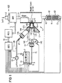
- FIG. 1 the form of a block diagram is very simplified with an internal combustion engine operated with excess air an exhaust gas aftertreatment system 1 assigned to it. Only those parts are shown that are for understanding the invention are necessary. In particular, is on the representation of the fuel circuit is omitted.
- an internal combustion engine Diesel engine shown and as a reducing agent for Aftertreatment of the exhaust gas becomes an aqueous urea solution used.
- the internal combustion engine BKM is the intake line 2 Air required for combustion is supplied.
- An injection system for example as a high-pressure accumulator injection system (Common rail) can be designed with injection valves, the fuel KST directly into the cylinders of the internal combustion engine Inject BKM is designated by reference number 3.
- the exhaust gas from the internal combustion engine BKM passes through a Exhaust line 4 to the exhaust gas aftertreatment system 1.
- a known engine control unit MSTG To control and regulate the internal combustion engine BKM is a known engine control unit MSTG only here schematically illustrated data and control line 5 with the Internal combustion engine BKM connected.
- Data - and Control line 5 are signals from sensors (e.g. temperature sensors for intake air, charge air, coolant, load sensor, Speed sensor) and signals for actuators (e.g. injection valve, Actuators) between the internal combustion engine BKM and the engine control unit MSTG.
- sensors e.g. temperature sensors for intake air, charge air, coolant, load sensor, Speed sensor
- actuators e.g. injection valve, Actuators
- the exhaust gas aftertreatment system 1 has a reduction catalytic converter 6, which contains a plurality of catalytic converter units 61, 62 connected in series. An oxidation catalytic converter can additionally be arranged downstream and / or upstream of the reduction catalytic converter 6. Furthermore, a metering control device DSTG is provided, which is assigned to a urea storage container 7 with an electrically controllable feed pump 8 for the urea.
- the urea storage container 7 has an electrical heating device 9 and sensors 10, 11 which detect the temperature of the urea or the fill level in the urea storage container 7.
- the signals of a temperature sensor 12 arranged upstream of the reduction catalytic converter 6 and of a NO x sensor 13 arranged downstream of the reduction catalytic converter 6 are also transferred to the metering control device DSTG.
- the DSTG dosing control unit controls an electromagnetic one Injection valve 14, with the urea via a line 15 With the help of the feed pump 8 from the urea storage container 7 is fed. Injection of urea by means of Injection valve 14 takes place in the exhaust line 4 upstream the reduction catalyst 6.
- the DSTG metering control unit is for mutual data transfer connected to the engine control unit MSTG via a bus system 16.
- the bus system 16 is used to calculate the relevant operating parameters to be metered urea quantity, such as. Speed, air mass, fuel mass, control path one Injection pump, exhaust gas mass flow, operating temperature, charge air temperature, Start of spraying etc. with the DSTG dosing control unit to hand over.
- the dosing control unit DSTG calculates the amount of urea to be injected.
- the urea is hydrolyzed and mixed.
- the catalytic reduction of the NO x in the exhaust gas to N 2 and H 2 O takes place in the catalyst units 61 and 62.
- valve 14 for introducing the urea into the Exhaust pipe 4 is used for a conventional low-pressure gasoline injection valve, the one with a wall 41 of the exhaust pipe 4 connected valve receiving body 17 (in the figure partially shown in section) and then is mechanically locked so that the injection valve 14 is centered in the radial and axial directions.
- the valve receptacle body 17 faces the exhaust pipe 4 facing away from the diameter of the injector body 141 adapted recess 171 by a Inner wall 172 is limited so that in the inserted state the longitudinal axis of the injector 14 is approximately rectangular to the wall 41 of the exhaust pipe 4 and the Outlet opening of the injector 14 just before or in Height of the wall 41 provided with a passage opening the exhaust pipe 4 is.
- the injection valve seal 14 in the recess 171 of the valve body 17 takes place by means of one pointing towards the wall 41 End of the injector body 141 arranged O-ring seal 142.
- the valve receiving body 17 is double-walled, wherein a wall encompassing the injector body 141 Inner wall 172 forms the further wall through an outer wall 173 of the valve receiving body 17 is formed, wherein the outer contour of the valve receiving body 17 in the direction the exhaust pipe 4 is tapered in a funnel shape, so that both the part of the injection valve body fixed in the recess 171 141 as well as that opposite the injector body 141 valve tip having a smaller diameter 143 is formed to form an air gap 144.
- the valve receiving body 17 is over the outer wall 173 firmly connected to the wall 41 of the exhaust pipe 4, in the case of a metallic valve body 17, e.g. welded.
- the valve receiving body 17 consist of temperature-resistant plastic or ceramic.
- the material used is said to be poor Be a heat conductor so that as little heat as possible from the exhaust gas and the exhaust pipe passes to the injection valve and on the other hand have a sufficiently high mechanical strength, to accommodate the injector and also in the operation of the Keep the engine safe.
- the injection valve 14 has an electrical connection 145 on, via which it by means of unspecified lines is connected to the DSTG dosing control unit.
- connection piece on the valve receiving body 17 174 provided for connecting a compressed air line 18, supplied via the cooling air for cooling the injection valve 14 becomes.
- the connection of the compressed air line 18 can advantageously by means of a conventional Quick coupling done.
- One of the signals serves as the compressed air generator the dosing control device DSTG electrically driven pump 19, preferably a secondary air pump as used for exhaust gas aftertreatment in gasoline engines are known or a mechanical driven by the crankshaft of the internal combustion engine Pump.
- the compressed air can be used to cool the injection valve 14 with supercharged internal combustion engines a throttled branch downstream of the charge air cooler removed and fed to the injector 14. This has the advantage that the temperature of the cooling air is relative low and therefore the cooling effect for the injection valve is great.
- the cooling air from this or from be taken from a secondary compressed air circuit.
- the injection valve 14 is activated during operation of the internal combustion engine intermittently depending on the current operating parameters the internal combustion engine BKM and the reduction catalytic converter 6 controlled.
- the compressed air generator for example the electric pump 19 is also activated, so that cooling air via the compressed air line 18 and the connector 174 in the air gap 144 between the inner wall 172 and the outer wall 173 of the valve receiving body 17 streams.
- the part of the injection valve close to the exhaust gas 14, in particular the valve tip 143 is flushed with cooling air.
- This cooling air is also due to the constructive Design of the valve receiving body 17 via the exhaust gas facing end face (jet exit side) of the injection valve 14 passed, whereby the heat absorption of the injection valve 14 is greatly reduced from the exhaust gas.
- the cooling air then flows into the exhaust pipe 4 and mixes there with the exhaust gas from the internal combustion engine. Because the share of additional air introduced for cooling the injection valve 14 in the exhaust pipe 4 based on the total exhaust gas mass flow in the exhaust pipe 4 is very low (typically approx. ⁇ 1%) and the unburned components in the exhaust gas of a diesel engine or a lean gasoline engine also very low are, this has no significant impact on the implementation the pollutants in the reduction catalyst 6.
- Injector valve face - air flow can cool the air flow in addition to shaping the injection jet can be used, which improves the preparation of the reducing agent aqueous urea solution is made possible.
- a pressure accumulator can be provided in the compressed air line 18 for the cooling air 20 (shown with dashed lines in FIG. 1) be provided during the operation of the Pump is filled and that after switching off the internal combustion engine and the pressure generator for a certain period of time, which is primarily from the volume of the accumulator is dependent, provides cooling air.
- Such pressure accumulator 20 can also be used in supercharged internal combustion engines be used.
- a check valve in the compressed air line 18 21 are provided.
- FIG 2 an embodiment is shown in which the Valve receiving body 17 on a double-walled Exhaust line 4 is arranged.
- Double-walled exhaust pipes are used to reduce heat loss and so a passive To support heating of the catalyst.
- the between the individual walls 41, 42 of the exhaust pipe 4 existing space 43, which serves as air gap insulation, is by means of a suitable Sealing and insulating element 44 (e.g. made of ceramic) at the mouth of the injection valve 14 into the exhaust pipe 4 completed. This means no reducing agent get into the space 43 between the two walls 41, 42.
- a suitable Sealing and insulating element 44 e.g. made of ceramic
- the invention was shown using two exemplary embodiments, in those with the injector installed the longitudinal axis of the injection valve in the valve receiving body approximately at right angles to a wall of the exhaust pipe lies. But it is also possible to use the valve body constructively so that when installed of the injection valve (14) whose longitudinal axis is based on the Flow direction of the exhaust gas with the wall (41) of the exhaust pipe forms an acute angle.
Landscapes
- Chemical & Material Sciences (AREA)
- Engineering & Computer Science (AREA)
- Chemical Kinetics & Catalysis (AREA)
- Health & Medical Sciences (AREA)
- Combustion & Propulsion (AREA)
- Biomedical Technology (AREA)
- Environmental & Geological Engineering (AREA)
- Analytical Chemistry (AREA)
- General Chemical & Material Sciences (AREA)
- Oil, Petroleum & Natural Gas (AREA)
- Toxicology (AREA)
- Mechanical Engineering (AREA)
- General Engineering & Computer Science (AREA)
- Exhaust Gas After Treatment (AREA)
Applications Claiming Priority (2)
| Application Number | Priority Date | Filing Date | Title |
|---|---|---|---|
| DE19856366A DE19856366C1 (de) | 1998-12-07 | 1998-12-07 | Vorrichtung und Verfahren zum Nachbehandeln von Abgasen einer mit Luftüberschuß arbeitenden Brennkraftmaschine |
| DE19856366 | 1998-12-07 |
Publications (2)
| Publication Number | Publication Date |
|---|---|
| EP1008732A1 true EP1008732A1 (fr) | 2000-06-14 |
| EP1008732B1 EP1008732B1 (fr) | 2004-03-03 |
Family
ID=7890234
Family Applications (1)
| Application Number | Title | Priority Date | Filing Date |
|---|---|---|---|
| EP99123870A Expired - Lifetime EP1008732B1 (fr) | 1998-12-07 | 1999-12-01 | Dispositif et procédé de post-traitement des gaz d'échappement d'un moteur à combustion interne à mélange pauvre |
Country Status (4)
| Country | Link |
|---|---|
| US (1) | US6192677B1 (fr) |
| EP (1) | EP1008732B1 (fr) |
| AT (1) | ATE261059T1 (fr) |
| DE (2) | DE19856366C1 (fr) |
Cited By (9)
| Publication number | Priority date | Publication date | Assignee | Title |
|---|---|---|---|---|
| EP1348840A1 (fr) * | 2002-03-28 | 2003-10-01 | Siemens Aktiengesellschaft | Dispositif de purification des gaz d'échappement |
| CN101346535B (zh) * | 2005-12-21 | 2012-02-15 | 罗伯特·博世有限公司 | 废气后处理装置 |
| WO2012049175A1 (fr) * | 2010-10-14 | 2012-04-19 | Emitec Gesellschaft Für Emissionstechnologie Mbh | Support pour un injecteur |
| WO2013135399A1 (fr) | 2012-03-14 | 2013-09-19 | Robert Bosch Gmbh | Dispositif d'injection |
| WO2015007614A1 (fr) * | 2013-07-16 | 2015-01-22 | Caterpillar Sarl | Carrosserie d'engin et engin de chantier |
| US9664081B2 (en) | 2007-07-24 | 2017-05-30 | Faurecia Emissions Control Technologies, Germany Gmbh | Assembly and method for introducing a reducing agent into the exhaust pipe of an exhaust system of an internal combustion engine |
| US9726064B2 (en) | 2015-04-30 | 2017-08-08 | Faurecia Emissions Control Technologies, Usa, Llc | Mixer for use in a vehicle exhaust system |
| US10933387B2 (en) | 2016-10-21 | 2021-03-02 | Faurecia Emissions Control Technologies, Usa, Llc | Reducing agent mixer |
| EP3792461A1 (fr) * | 2019-09-16 | 2021-03-17 | Albonair GmbH | Buse d'injection chauffée |
Families Citing this family (126)
| Publication number | Priority date | Publication date | Assignee | Title |
|---|---|---|---|---|
| DE19806265C5 (de) * | 1998-02-16 | 2004-07-22 | Siemens Ag | Dosiersystem |
| DE19919426C1 (de) * | 1999-04-28 | 2000-03-30 | Siemens Ag | Ventilaufnahmevorrichtung für ein Dosierventil einer Abgasnachbehandlungsanlage |
| US6363771B1 (en) | 1999-11-24 | 2002-04-02 | Caterpillar Inc. | Emissions diagnostic system |
| DE19961947A1 (de) * | 1999-12-22 | 2001-06-28 | Bosch Gmbh Robert | Vorrichtung und Verfahren zur Erzeugung eines Reduktionsmittel-Luftgemisches |
| US6526746B1 (en) * | 2000-08-02 | 2003-03-04 | Ford Global Technologies, Inc. | On-board reductant delivery assembly |
| DE10047516A1 (de) * | 2000-09-22 | 2002-04-18 | Bosch Gmbh Robert | Verfahren und Vorrichtung zur Dosierung eines Reduktionsmittels zur Entfernung von Stickoxiden aus Abgasen |
| DE10047531A1 (de) * | 2000-09-22 | 2002-04-18 | Bosch Gmbh Robert | Vorrichtung zur Dosierung eines Reduktionsmittels |
| DE10116214A1 (de) * | 2001-03-30 | 2002-10-10 | Bosch Gmbh Robert | Vorrichtung zum Nachbehandeln von Abgasen einer Brennkraftmaschine |
| JP3888519B2 (ja) * | 2001-09-12 | 2007-03-07 | 株式会社デンソー | 排気浄化装置 |
| DE10149275B4 (de) * | 2001-10-05 | 2004-07-15 | Purem Abgassysteme Gmbh & Co. Kg | Verfahren und Vorrichtung zum Dosieren eines flüssigen Reduktionsmittels |
| DE20119513U1 (de) | 2001-12-03 | 2002-02-28 | PUREM Abgassysteme GmbH & Co. KG, 58706 Menden | Reduktionsmitteldosiereinrichtung |
| DE20119514U1 (de) | 2001-12-03 | 2002-02-28 | PUREM Abgassysteme GmbH & Co. KG, 58706 Menden | Reduktionsmitteldosiereinrichtung |
| JP3861746B2 (ja) * | 2002-05-17 | 2006-12-20 | トヨタ自動車株式会社 | 内燃機関の排気浄化装置 |
| FR2850704A1 (fr) * | 2003-01-31 | 2004-08-06 | Jean Claude Fayard | Procede de post-injection de gazole pour la regeneration de systemes de filtration des gaz d'echappement de moteur diesel |
| US7614213B2 (en) * | 2003-09-19 | 2009-11-10 | Nissan Diesel Motor Co., Ltd. | Engine exhaust emission purification apparatus |
| WO2005033479A1 (fr) * | 2003-09-30 | 2005-04-14 | Nissan Diesel Motor Co., Ltd. | Dispositif d'epuration de gaz d'echappement de moteur |
| ATE520868T1 (de) * | 2003-10-02 | 2011-09-15 | Nissan Diesel Motor Co | Abgasreiniger für motor |
| JP2005226528A (ja) * | 2004-02-12 | 2005-08-25 | Tokyo Roki Co Ltd | Scrマフラー |
| JP2007529678A (ja) * | 2004-03-16 | 2007-10-25 | パイロバン リミテッド | 排気フィルタ再生過程、方法及び装置 |
| DE102004015805B4 (de) * | 2004-03-29 | 2007-07-26 | J. Eberspächer GmbH & Co. KG | Vorrichtung zum Einbringen einer Flüssigkeit in einen Abgasstrang |
| US8047452B2 (en) * | 2004-04-26 | 2011-11-01 | Tenneco Automotive Operating Company Inc. | Method and apparatus for injecting atomized fluids |
| US20060013704A1 (en) * | 2004-06-30 | 2006-01-19 | Teruya Sawada | Liquid aeration delivery apparatus |
| DE102004048336A1 (de) * | 2004-10-01 | 2006-04-13 | J. Eberspächer GmbH & Co. KG | Abgasanlage für eine Brennkraftmaschine |
| DE102004048075A1 (de) * | 2004-10-02 | 2006-04-06 | Robert Bosch Gmbh | Dosiersystem zur Schadstoffreduktion in Kraftfahrzeugabgasen |
| JP3714559B1 (ja) * | 2004-11-05 | 2005-11-09 | 日産ディーゼル工業株式会社 | 排気浄化装置 |
| AT501091B1 (de) * | 2004-11-15 | 2006-12-15 | Pankl Emission Control Systems | Abgasreinigungsvorrichtung |
| US20060101810A1 (en) * | 2004-11-15 | 2006-05-18 | Angelo Theodore G | System for dispensing fuel into an exhaust system of a diesel engine |
| DE102004056791B4 (de) * | 2004-11-24 | 2007-04-19 | J. Eberspächer GmbH & Co. KG | Abgasanlage |
| DE502004010210D1 (de) * | 2004-12-30 | 2009-11-19 | Grundfos Nonox As | Dosierpumpenaggregat |
| ATE360137T1 (de) * | 2004-12-30 | 2007-05-15 | Grundfos Management As | Dosierpumpenaggregat |
| DE502004005576D1 (de) * | 2004-12-30 | 2008-01-03 | Grundfos Nonox As | Vorrichtung zur Erzeugung eines Reduktionsmittel-Luft-Gemisches |
| US7213394B2 (en) * | 2005-01-27 | 2007-05-08 | Cummins Inc. | Engine blowby injector and injection system and method for injecting blowby |
| JP4485400B2 (ja) * | 2005-04-08 | 2010-06-23 | トヨタ自動車株式会社 | 内燃機関の排気浄化装置 |
| SE529591C2 (sv) | 2006-02-08 | 2007-09-25 | Stt Emtec Ab | Insprutningsanordning |
| DE602006017449D1 (de) | 2006-07-12 | 2010-11-18 | Delphi Tech Holding Sarl | Fluiddosiervorrichtung |
| DE602007009848D1 (de) * | 2006-07-12 | 2010-11-25 | Delphi Tech Holding Sarl | Isolierte Reagenzdosiervorrichtung |
| DE102006053804B4 (de) | 2006-11-15 | 2018-04-19 | Robert Bosch Gmbh | Flanschverbindung |
| US8240134B2 (en) | 2006-12-05 | 2012-08-14 | Mack Trucks, Inc. | Engine with exhaust cooling and method |
| DE102006059953B4 (de) * | 2006-12-19 | 2009-08-20 | Pierburg Gmbh | Luftbereitstellungseinrichtung |
| DE102006061730A1 (de) | 2006-12-28 | 2008-07-03 | Robert Bosch Gmbh | SCR-Injektionseinrichtung |
| US8171721B2 (en) | 2007-01-22 | 2012-05-08 | International Engine Intellectual Property Company, Llc | Closed loop control of exhaust system fluid dosing |
| US7526950B2 (en) * | 2007-01-31 | 2009-05-05 | Ford Global Technologies, Llc | Emission control diagnostic system and method |
| DE102008006323B4 (de) * | 2007-02-27 | 2014-04-30 | Eichenauer Heizelemente Gmbh & Co. Kg | Reduktionsmittelversorgungssystem für einen Abgasreinigungskatalysator eines Verbrennungsmotors und Steckverbindung zum Anschließen von beheizbaren Flüssigkeitsleitungen |
| US8453436B2 (en) * | 2007-03-08 | 2013-06-04 | Mack Trucks, Inc. | Aftertreatment injector anti-fouling device |
| US7762061B2 (en) * | 2007-04-09 | 2010-07-27 | Emcon Technologies Llc | Apparatus and method for operating an emission abatement system |
| US7954312B2 (en) * | 2007-05-09 | 2011-06-07 | Ford Global Technologies, Llc | Approach for detecting reductant availability and make-up |
| US8915064B2 (en) * | 2007-05-15 | 2014-12-23 | Donaldson Company, Inc. | Exhaust gas flow device |
| US7878183B2 (en) * | 2007-07-17 | 2011-02-01 | Cummins Filtration Ip, Inc. | Apparatus, system, and method to provide air to a doser injector nozzle |
| US8281570B2 (en) * | 2007-08-09 | 2012-10-09 | Caterpillar Inc. | Reducing agent injector having purge heater |
| JP4886636B2 (ja) * | 2007-09-04 | 2012-02-29 | 日野自動車株式会社 | インジェクタの取付構造 |
| DE102007048560A1 (de) | 2007-10-09 | 2009-04-23 | Audi Ag | Vorrichtung zum Nachbehandeln von Abgasen einer magerlauffähigen Brennkraftmaschine |
| JP5041151B2 (ja) * | 2007-11-09 | 2012-10-03 | 三菱自動車工業株式会社 | 内燃機関の排気浄化装置 |
| DE102008008564A1 (de) | 2008-02-08 | 2009-08-13 | Robert Bosch Gmbh | Dosiervorrichtung zur Schadstoffverminderung in Abgasen |
| DE102008013960A1 (de) * | 2008-03-12 | 2009-09-17 | Albonair Gmbh | Dosiersystem zur Eindüsung einer Harnstofflösung in den Abgasstrom eines Verbrennungsmotors |
| DE602008000877D1 (de) * | 2008-03-28 | 2010-05-06 | Magneti Marelli Spa | Haltevorrichtung für einen Injektor in einem Abgassystem einer Brennkraftmaschine |
| DE102008040476C5 (de) * | 2008-07-16 | 2020-02-13 | Faurecia Abgastechnik Gmbh | Injektionsvorrichtung für die Abgasanlage eines Kraftfahrzeugs |
| US8079211B2 (en) * | 2008-11-06 | 2011-12-20 | Ford Global Technologies, Llc | Bypass purge for protecting against formation of reductant deposits |
| DE102008057258A1 (de) * | 2008-11-13 | 2010-05-20 | Albonair Gmbh | Komponententräger für ein Dosiersystem |
| US8499548B2 (en) | 2008-12-17 | 2013-08-06 | Donaldson Company, Inc. | Flow device for an exhaust system |
| US20100170225A1 (en) * | 2009-01-08 | 2010-07-08 | Caterpillar Inc. | Exhaust treatment system having a reductant supply system |
| US8116961B2 (en) | 2009-06-03 | 2012-02-14 | Ford Global Technologies, Llc | Controlling of a vehicle responsive to reductant conditions |
| US8800271B2 (en) * | 2009-09-18 | 2014-08-12 | Kwang Sung Co., Ltd. | Selective catalyst reduction system with bypass system |
| CN101712277B (zh) * | 2009-09-27 | 2013-07-24 | 无锡市凯龙汽车设备制造有限公司 | 基于scr和etr的商用车减排节能集成排气系统 |
| DE102009048121A1 (de) | 2009-10-02 | 2011-04-07 | Technische Universität Bergakademie Freiberg | Abgasvorrichtung für Verbrennungsgase |
| DE102009048514A1 (de) * | 2009-10-07 | 2011-04-14 | Emitec Gesellschaft Für Emissionstechnologie Mbh | Injektorhalterung |
| US8429903B2 (en) * | 2009-12-22 | 2013-04-30 | Caterpillar Inc. | Radial mounting for regeneration device |
| US8539761B2 (en) * | 2010-01-12 | 2013-09-24 | Donaldson Company, Inc. | Flow device for exhaust treatment system |
| DE102010004612A1 (de) * | 2010-01-13 | 2011-07-14 | Emitec Gesellschaft für Emissionstechnologie mbH, 53797 | Vorrichtung mit einem Tank und einer Fördereinheit für Reduktionsmittel |
| US8973895B2 (en) | 2010-02-10 | 2015-03-10 | Tenneco Automotive Operating Company Inc. | Electromagnetically controlled injector having flux bridge and flux break |
| US8740113B2 (en) | 2010-02-10 | 2014-06-03 | Tenneco Automotive Operating Company, Inc. | Pressure swirl flow injector with reduced flow variability and return flow |
| BR112012019877A2 (pt) * | 2010-02-10 | 2016-04-26 | Tenneco Automotive Operating | injetor de fluxo em redemoinho por pressão com variabilidade de fluxo reduzido e fluxo de retorno |
| US9683472B2 (en) | 2010-02-10 | 2017-06-20 | Tenneco Automotive Operating Company Inc. | Electromagnetically controlled injector having flux bridge and flux break |
| SE535167C2 (sv) * | 2010-06-02 | 2012-05-08 | Scania Cv Ab | Arrangemang för tillförsel av ett medel i ett avgasflöde |
| JP5768330B2 (ja) * | 2010-06-11 | 2015-08-26 | いすゞ自動車株式会社 | 排気管内燃料噴射システム |
| JP5768331B2 (ja) | 2010-06-11 | 2015-08-26 | いすゞ自動車株式会社 | 排気管内燃料噴射システム |
| EP3267005B2 (fr) | 2010-06-22 | 2023-12-27 | Donaldson Company, Inc. | Dispositif de post-traitement d'échappement |
| DE102010043735A1 (de) * | 2010-11-11 | 2012-05-16 | Robert Bosch Gmbh | Einspritzdüse |
| DE102010055520B4 (de) * | 2010-12-22 | 2023-10-05 | Voss Automotive Gmbh | Konfektionierte Medienleitung sowie Verwendung in einem SCR-Katalysator-System |
| EP2476874B1 (fr) * | 2011-01-13 | 2013-04-03 | Delphi Technologies Holding S.à.r.l. | Dispositif d'injection pour réactif |
| DE102011009620A1 (de) * | 2011-01-28 | 2012-08-02 | Emitec Gesellschaft Für Emissionstechnologie Mbh | Abgasbehandlungsvorrichtung mit einem Injektor zur Zufuhr eines Fluids |
| US9719395B2 (en) | 2011-05-10 | 2017-08-01 | Albonair Gmbh | Component carrier for a dosing system |
| US20130014496A1 (en) * | 2011-07-15 | 2013-01-17 | Caterpillar Inc. | Cooling system for engine aftertreatment system |
| US9896980B2 (en) | 2011-07-26 | 2018-02-20 | Paccar Inc | Exhaust aftertreatment supplying a reducing agent |
| CN103814194B (zh) | 2011-08-22 | 2016-10-19 | 康明斯排放处理公司 | 用于排气后处理系统的尿素投配的装置、方法及系统 |
| DE102011053742A1 (de) | 2011-09-19 | 2013-03-21 | Cummins Ltd. | Wärmetauscher für eine Dosiereinheit einer SCR-Abgasnachbehandlungseinrichtung |
| JP5787082B2 (ja) * | 2011-10-14 | 2015-09-30 | トヨタ自動車株式会社 | 添加弁シール構造 |
| DE102011086017A1 (de) * | 2011-11-09 | 2013-05-16 | Robert Bosch Gmbh | Dosiermodul |
| DE102011087085A1 (de) * | 2011-11-25 | 2013-05-29 | Robert Bosch Gmbh | Kühleinrichtung mit Drainagebohrungen |
| DE102011087288A1 (de) | 2011-11-29 | 2013-05-29 | Robert Bosch Gmbh | Abgasnachbehandlungssystem und Verfahren zum Einbringen eines Reduktionsmittels in einen Abgaskanal einer Brennkraftmaschine |
| DE102012201203A1 (de) | 2012-01-27 | 2013-08-01 | Robert Bosch Gmbh | Wassergekühltes Dosiermodul |
| DE102012202188A1 (de) * | 2012-02-14 | 2013-08-14 | Robert Bosch Gmbh | Dosiermodul zum Einbringen eines flüssigen Stoffes in das Abgas einer Brennkraftmaschine |
| DE102012205389A1 (de) | 2012-04-03 | 2013-10-10 | Robert Bosch Gmbh | Kühlvorrichtung für Anschlussstück |
| US8938954B2 (en) | 2012-04-19 | 2015-01-27 | Donaldson Company, Inc. | Integrated exhaust treatment device having compact configuration |
| US8978364B2 (en) | 2012-05-07 | 2015-03-17 | Tenneco Automotive Operating Company Inc. | Reagent injector |
| US8910884B2 (en) | 2012-05-10 | 2014-12-16 | Tenneco Automotive Operating Company Inc. | Coaxial flow injector |
| DE102012019951B4 (de) * | 2012-10-11 | 2025-08-14 | Man Energy Solutions Se | Abgasnachbehandlungssystem für eine Brennkraftmaschine |
| CA2900801C (fr) | 2013-02-15 | 2021-01-26 | Donaldson Company, Inc. | Agencement de dosage et de melange destine a etre utilise dans le traitement postcombustion des gaz d'echappement |
| US8973355B2 (en) | 2013-03-15 | 2015-03-10 | Tenneco Automotive Operating Company Inc. | Multi-layer liquid-cooled mount |
| US8997467B2 (en) | 2013-03-15 | 2015-04-07 | Caterpillar Inc. | System and method for post-shutdown temperature management and purge |
| DE102013205309A1 (de) * | 2013-03-26 | 2014-10-02 | Robert Bosch Gmbh | Vorrichtung zum Zumessen von Fluid |
| WO2014157286A1 (fr) * | 2013-03-28 | 2014-10-02 | ヤンマー株式会社 | Dispositif de moteur |
| DE102013007380B4 (de) | 2013-04-26 | 2017-04-06 | Audi Ag | Abgasanlage |
| DE102013008693B4 (de) | 2013-05-22 | 2016-11-10 | Audi Ag | Verfahren zum Betreiben einer Abgasanlage sowie entsprechende Abgasanlage |
| IN2013DE01690A (fr) * | 2013-06-05 | 2015-07-10 | Caterpillar Global Mining Expanded Products Pty Ltd | |
| DE102013215594B4 (de) | 2013-08-07 | 2026-03-19 | Bayerische Motoren Werke Aktiengesellschaft | Abgasanlage für eine Brennkraftmaschine |
| JP6133183B2 (ja) * | 2013-09-25 | 2017-05-24 | キャタピラー エス エー アール エル | エンジンの排気浄化装置 |
| DE102013224739A1 (de) | 2013-12-03 | 2015-06-03 | Robert Bosch Gmbh | Dosiermodul zur AdBlue-Dosierung |
| EP2891570B1 (fr) * | 2014-03-31 | 2017-12-06 | Komatsu Ltd. | Engin de travaux avec unité de refroidissement du compartiment moteur |
| DE102014107519A1 (de) * | 2014-05-28 | 2015-12-03 | Emitec France S.A.S | Heizung für eine Vorrichtung zur Bereitstellung eines flüssigen Additivs |
| GB2539888A (en) * | 2015-06-29 | 2017-01-04 | Delphi Int Operations Luxembourg Sarl | Reductant injector cooling system |
| DE102015016244A1 (de) * | 2015-12-16 | 2017-06-22 | Albonair Gmbh | Hitzeresistente Reduktionsmitteleinspritzdüse |
| JP6477616B2 (ja) * | 2016-06-30 | 2019-03-06 | トヨタ自動車株式会社 | 排気浄化システムの冷却装置 |
| KR101815770B1 (ko) * | 2016-06-30 | 2018-01-05 | 주식회사 현대케피코 | 요소수 인젝터 모듈 |
| CN110546355B (zh) | 2017-04-13 | 2021-07-30 | 康明斯排放处理公司 | 用于内燃发动机的后处理系统的配给模块 |
| GB2568936B (en) | 2017-12-01 | 2019-12-25 | Ford Global Tech Llc | Liquid cooled injector |
| US10287948B1 (en) | 2018-04-23 | 2019-05-14 | Faurecia Emissions Control Technologies, Usa, Llc | High efficiency mixer for vehicle exhaust system |
| US10316721B1 (en) | 2018-04-23 | 2019-06-11 | Faurecia Emissions Control Technologies, Usa, Llc | High efficiency mixer for vehicle exhaust system |
| US10704444B2 (en) | 2018-08-21 | 2020-07-07 | Tenneco Automotive Operating Company Inc. | Injector fluid filter with upper and lower lip seal |
| US10787946B2 (en) | 2018-09-19 | 2020-09-29 | Faurecia Emissions Control Technologies, Usa, Llc | Heated dosing mixer |
| JP2020176602A (ja) * | 2019-04-22 | 2020-10-29 | 株式会社デンソー | 流体噴射装置及び流体噴射システム |
| US11808192B2 (en) | 2019-08-14 | 2023-11-07 | Cummins Emission Solutions Inc. | Exhaust gas aftertreatment system |
| DE102020125821A1 (de) * | 2020-10-02 | 2022-04-07 | AICHELIN Holding GmbH | Vorrichtung und Verfahren zur Abgasreinigung von Brennern mittels SCR |
| CN113513400B (zh) * | 2021-05-18 | 2022-07-12 | 无锡市博瑞斯通科技技术有限公司 | 一种气体冷却自动控制喷嘴 |
| CN113669137A (zh) * | 2021-09-30 | 2021-11-19 | 潍柴动力股份有限公司 | 一种尿素喷射装置、尿素喷射系统及尿素喷射控制方法 |
| DE102023136671A1 (de) * | 2023-12-22 | 2025-06-26 | Hug Engineering Ag | Verfahren zur Steuerung eines Volumenstroms von Zerstäubungsgas in einer Katalysatorvorrichtung und Katalysatorvorrichtung |
| CN121266340A (zh) * | 2025-12-09 | 2026-01-06 | 西安航天动力试验技术研究所 | 一种液体火箭发动机推进剂废气废液处理装置及处理方法 |
Citations (3)
| Publication number | Priority date | Publication date | Assignee | Title |
|---|---|---|---|---|
| DE4436397A1 (de) * | 1994-10-12 | 1996-04-18 | Bosch Gmbh Robert | Einrichtung zum Nachbehandeln von Abgasen |
| US5601792A (en) * | 1992-02-24 | 1997-02-11 | Hug; Hans T. | Cleaning exhaust gases from combustion installations |
| DE19806265C1 (de) * | 1998-02-16 | 1999-07-22 | Siemens Ag | Dosiersystem |
Family Cites Families (9)
| Publication number | Priority date | Publication date | Assignee | Title |
|---|---|---|---|---|
| DE2158119A1 (de) * | 1971-11-24 | 1973-05-30 | Bosch Gmbh Robert | Abgasentgiftungsanlage |
| JPS59158312A (ja) * | 1983-02-25 | 1984-09-07 | Hitachi Ltd | デイ−ゼルエンジン排気浄化装置 |
| FR2548264B1 (fr) * | 1983-06-16 | 1985-12-13 | Renault | Regeneration des filtres a particules, notamment pour moteurs diesel |
| JPS60216019A (ja) * | 1984-04-12 | 1985-10-29 | Nissan Motor Co Ltd | 内燃機関の排気微粒子処理装置 |
| DE4436415A1 (de) * | 1994-10-12 | 1996-04-18 | Bosch Gmbh Robert | Einrichtung zum Nachbehandeln von Abgasen einer selbstzündenden Brennkraftmaschine |
| DE19726392A1 (de) * | 1997-06-21 | 1998-12-24 | Bosch Gmbh Robert | Gemischabgabevorrichtung |
| DE19738859A1 (de) * | 1997-09-05 | 1999-03-11 | Bosch Gmbh Robert | Gemischabgabevorrichtung |
| DE19743337C1 (de) * | 1997-09-30 | 1999-01-07 | Siemens Ag | NOx-Reduktionssystem mit einer Einrichtung zur Reduktionsmitteldosierung |
| US6085519A (en) * | 1998-11-23 | 2000-07-11 | General Motors Corporation | Anti-coking air injection apparatus for an internal combustion engine |
-
1998
- 1998-12-07 DE DE19856366A patent/DE19856366C1/de not_active Expired - Lifetime
-
1999
- 1999-12-01 EP EP99123870A patent/EP1008732B1/fr not_active Expired - Lifetime
- 1999-12-01 DE DE59908721T patent/DE59908721D1/de not_active Expired - Lifetime
- 1999-12-01 AT AT99123870T patent/ATE261059T1/de active
- 1999-12-07 US US09/456,124 patent/US6192677B1/en not_active Expired - Lifetime
Patent Citations (3)
| Publication number | Priority date | Publication date | Assignee | Title |
|---|---|---|---|---|
| US5601792A (en) * | 1992-02-24 | 1997-02-11 | Hug; Hans T. | Cleaning exhaust gases from combustion installations |
| DE4436397A1 (de) * | 1994-10-12 | 1996-04-18 | Bosch Gmbh Robert | Einrichtung zum Nachbehandeln von Abgasen |
| DE19806265C1 (de) * | 1998-02-16 | 1999-07-22 | Siemens Ag | Dosiersystem |
Cited By (10)
| Publication number | Priority date | Publication date | Assignee | Title |
|---|---|---|---|---|
| EP1348840A1 (fr) * | 2002-03-28 | 2003-10-01 | Siemens Aktiengesellschaft | Dispositif de purification des gaz d'échappement |
| CN101346535B (zh) * | 2005-12-21 | 2012-02-15 | 罗伯特·博世有限公司 | 废气后处理装置 |
| US9664081B2 (en) | 2007-07-24 | 2017-05-30 | Faurecia Emissions Control Technologies, Germany Gmbh | Assembly and method for introducing a reducing agent into the exhaust pipe of an exhaust system of an internal combustion engine |
| WO2012049175A1 (fr) * | 2010-10-14 | 2012-04-19 | Emitec Gesellschaft Für Emissionstechnologie Mbh | Support pour un injecteur |
| WO2013135399A1 (fr) | 2012-03-14 | 2013-09-19 | Robert Bosch Gmbh | Dispositif d'injection |
| DE102012203957A1 (de) | 2012-03-14 | 2013-09-19 | Robert Bosch Gmbh | Einspritzvorrichtung |
| WO2015007614A1 (fr) * | 2013-07-16 | 2015-01-22 | Caterpillar Sarl | Carrosserie d'engin et engin de chantier |
| US9726064B2 (en) | 2015-04-30 | 2017-08-08 | Faurecia Emissions Control Technologies, Usa, Llc | Mixer for use in a vehicle exhaust system |
| US10933387B2 (en) | 2016-10-21 | 2021-03-02 | Faurecia Emissions Control Technologies, Usa, Llc | Reducing agent mixer |
| EP3792461A1 (fr) * | 2019-09-16 | 2021-03-17 | Albonair GmbH | Buse d'injection chauffée |
Also Published As
| Publication number | Publication date |
|---|---|
| EP1008732B1 (fr) | 2004-03-03 |
| DE19856366C1 (de) | 2000-04-20 |
| US6192677B1 (en) | 2001-02-27 |
| ATE261059T1 (de) | 2004-03-15 |
| DE59908721D1 (de) | 2004-04-08 |
Similar Documents
| Publication | Publication Date | Title |
|---|---|---|
| EP1008732B1 (fr) | Dispositif et procédé de post-traitement des gaz d'échappement d'un moteur à combustion interne à mélange pauvre | |
| EP1192337B1 (fr) | Dispositif de logement pour une soupape de dosage d'une installation de traitement de gaz brules | |
| DE112008001962B4 (de) | Baugruppe und Verfahren zur Einbringung eines Reduktionsmittels in die Abgasleitung einer Abgasanlage einer Verbrennungskraftmaschine | |
| EP1244512B1 (fr) | Dispositif et procede de traitement subsequent de gaz d'echappement | |
| DE10349126B4 (de) | Verfahren und Vorrichtung zur Steuerung eines SCR-Katalysators | |
| EP1232334B1 (fr) | Dispositif et procede de denitrogenisation des gaz d'echappement d'un moteur a combustion interne | |
| EP2907984B1 (fr) | Moteur à combustion interne | |
| DE102007051510B4 (de) | Baugruppe zur Einbringung eines Reduktionsmittels in die Abgasleitung einer Abgasanlage einer Verbrennungskraftmaschine | |
| EP0907010A2 (fr) | Procédé et dispositif de commande d'un moteur à combustion interne à mélange pauvre | |
| DE4436397A1 (de) | Einrichtung zum Nachbehandeln von Abgasen | |
| DE102018220715A1 (de) | Abgasnachbehandlungssystem sowie Verfahren zur Abgasnachbehandlung eines Verbrennungsmotors | |
| DE102014206339A1 (de) | Reduktor-abgabeeinheit zur selektiven katalytischen reduktion bei fahrzeugen mit reduktionsmittel-erwärmung | |
| EP2198135A1 (fr) | Dispositif de traitement des gaz d'échappement d'un moteur à combustion interne capable de fonctionner en conditions pauvres | |
| DE102009038835A1 (de) | Abgasreinigungsanlage für eine Brennkraftmaschine | |
| DE102005062120A1 (de) | Verfahren und Vorrichtung zur Überwachung eines Abgasnachbehandlungssystems | |
| DE102019131256B4 (de) | Abgasnachbehandlungssystem mit einem Oxidationskomponentenbypass für Niedrigtemperatur-SCR | |
| DE20119514U1 (de) | Reduktionsmitteldosiereinrichtung | |
| DE102007034316A1 (de) | Baugruppe sowie Verfahren zur Einbringung eines Reduktionsmittels in die Abgasleitung einer Abgasanlage einer Verbrennungskraftmaschine | |
| EP3385520B1 (fr) | Dispositif de traitement de gaz d'échappement pour un moteur à combustion | |
| WO2019072725A1 (fr) | Procédé pour faire fonctionner un moteur diesel et moteur diesel avec contrôle de la concentration en nh3 | |
| EP1957767B1 (fr) | Procede de traitement final des gaz d'echappement de moteurs a combustion interne et dispositif en vue de la mise en oeuvre du procede | |
| DE102014004439B4 (de) | Verfahren zum Betreiben eines an eine Kraftfahrzeugbrennkraftmaschine angeschlossenen Abgasreinigungssystems umfassend einen SCR-Katalysator | |
| DE112017007440T5 (de) | Dosiermodul zur Verwendung in Nachbehandlungssystemen für Verbrennungsmotoren | |
| DE102017006738B4 (de) | Vorrichtung und Verfahren für Abgasreinigungssysteme von Dieselfahrzeugen, insbesondere zur Nachrüstung von Diesel-Bestandsfahrzeugen mit einem Dieselpartikelfilter, insbesondere für den innerstädtischen Fahrbetrieb | |
| DE102019212883A1 (de) | Mischvorrichtung |
Legal Events
| Date | Code | Title | Description |
|---|---|---|---|
| PUAI | Public reference made under article 153(3) epc to a published international application that has entered the european phase |
Free format text: ORIGINAL CODE: 0009012 |
|
| AK | Designated contracting states |
Kind code of ref document: A1 Designated state(s): AT DE FR IT |
|
| AX | Request for extension of the european patent |
Free format text: AL;LT;LV;MK;RO;SI |
|
| 17P | Request for examination filed |
Effective date: 20001213 |
|
| AKX | Designation fees paid |
Free format text: AT DE FR IT |
|
| 17Q | First examination report despatched |
Effective date: 20010926 |
|
| GRAP | Despatch of communication of intention to grant a patent |
Free format text: ORIGINAL CODE: EPIDOSNIGR1 |
|
| GRAS | Grant fee paid |
Free format text: ORIGINAL CODE: EPIDOSNIGR3 |
|
| GRAA | (expected) grant |
Free format text: ORIGINAL CODE: 0009210 |
|
| AK | Designated contracting states |
Kind code of ref document: B1 Designated state(s): AT DE FR IT |
|
| REF | Corresponds to: |
Ref document number: 59908721 Country of ref document: DE Date of ref document: 20040408 Kind code of ref document: P |
|
| ET | Fr: translation filed | ||
| PLBE | No opposition filed within time limit |
Free format text: ORIGINAL CODE: 0009261 |
|
| STAA | Information on the status of an ep patent application or granted ep patent |
Free format text: STATUS: NO OPPOSITION FILED WITHIN TIME LIMIT |
|
| 26N | No opposition filed |
Effective date: 20041206 |
|
| REG | Reference to a national code |
Ref country code: FR Ref legal event code: TP |
|
| REG | Reference to a national code |
Ref country code: AT Ref legal event code: HC Ref document number: 261059 Country of ref document: AT Kind code of ref document: T Owner name: JOHNSON MATTHEY CATALYSTS (GERMANY) GMBH, DE Effective date: 20120411 |
|
| REG | Reference to a national code |
Ref country code: FR Ref legal event code: CD Owner name: JOHNSON MATTHEY CATALYSTS GERMANY GMBH, DE Effective date: 20120615 |
|
| REG | Reference to a national code |
Ref country code: DE Ref legal event code: R082 Ref document number: 59908721 Country of ref document: DE Representative=s name: FDST PATENTANWAELTE FREIER DOERR STAMMLER TSCH, DE |
|
| REG | Reference to a national code |
Ref country code: DE Ref legal event code: R082 Ref document number: 59908721 Country of ref document: DE Representative=s name: FDST PATENTANWAELTE FREIER DOERR STAMMLER TSCH, DE Effective date: 20121004 Ref country code: DE Ref legal event code: R081 Ref document number: 59908721 Country of ref document: DE Owner name: JOHNSON MATTHEY CATALYSTS (GERMANY) GMBH, DE Free format text: FORMER OWNER: ARGILLON GMBH, 96257 REDWITZ, DE Effective date: 20121004 |
|
| REG | Reference to a national code |
Ref country code: FR Ref legal event code: PLFP Year of fee payment: 17 |
|
| REG | Reference to a national code |
Ref country code: FR Ref legal event code: PLFP Year of fee payment: 18 |
|
| REG | Reference to a national code |
Ref country code: FR Ref legal event code: PLFP Year of fee payment: 19 |
|
| PGFP | Annual fee paid to national office [announced via postgrant information from national office to epo] |
Ref country code: DE Payment date: 20181126 Year of fee payment: 20 Ref country code: AT Payment date: 20181121 Year of fee payment: 20 |
|
| PGFP | Annual fee paid to national office [announced via postgrant information from national office to epo] |
Ref country code: FR Payment date: 20181127 Year of fee payment: 20 Ref country code: IT Payment date: 20181122 Year of fee payment: 20 |
|
| REG | Reference to a national code |
Ref country code: DE Ref legal event code: R071 Ref document number: 59908721 Country of ref document: DE |
|
| REG | Reference to a national code |
Ref country code: DE Ref legal event code: R082 Ref document number: 59908721 Country of ref document: DE Representative=s name: BARDEHLE PAGENBERG PARTNERSCHAFT MBB PATENTANW, DE |
|
| REG | Reference to a national code |
Ref country code: AT Ref legal event code: MK07 Ref document number: 261059 Country of ref document: AT Kind code of ref document: T Effective date: 20191201 |