EP1008749A2 - Machine à pistons axiaux - Google Patents
Machine à pistons axiaux Download PDFInfo
- Publication number
- EP1008749A2 EP1008749A2 EP99124140A EP99124140A EP1008749A2 EP 1008749 A2 EP1008749 A2 EP 1008749A2 EP 99124140 A EP99124140 A EP 99124140A EP 99124140 A EP99124140 A EP 99124140A EP 1008749 A2 EP1008749 A2 EP 1008749A2
- Authority
- EP
- European Patent Office
- Prior art keywords
- spring
- cylinder drum
- control body
- piston machine
- axial piston
- Prior art date
- Legal status (The legal status is an assumption and is not a legal conclusion. Google has not performed a legal analysis and makes no representation as to the accuracy of the status listed.)
- Granted
Links
Images


Classifications
-
- F—MECHANICAL ENGINEERING; LIGHTING; HEATING; WEAPONS; BLASTING
- F04—POSITIVE - DISPLACEMENT MACHINES FOR LIQUIDS; PUMPS FOR LIQUIDS OR ELASTIC FLUIDS
- F04B—POSITIVE-DISPLACEMENT MACHINES FOR LIQUIDS; PUMPS
- F04B1/00—Multi-cylinder machines or pumps characterised by number or arrangement of cylinders
- F04B1/12—Multi-cylinder machines or pumps characterised by number or arrangement of cylinders having cylinder axes coaxial with, or parallel or inclined to, main shaft axis
- F04B1/20—Multi-cylinder machines or pumps characterised by number or arrangement of cylinders having cylinder axes coaxial with, or parallel or inclined to, main shaft axis having rotary cylinder block
- F04B1/2007—Arrangements for pressing the cylinder barrel against the valve plate, e.g. by fluid pressure
Definitions
- the invention relates to an improvement in one Axial piston machine either in swash plate design or in inclined axis construction to improve the system of the Cylinder drum on the control body.
- a swash plate type axial piston machine is, for example, from the DE 196 45 580 C1 known.
- emerging axial piston machine is one in the Cylinder drum with a centrally arranged spiral spring provided, which extends over a into the cylinder drum supported ring on the cylinder drum and over several pins acting on a retraction ball.
- the Retraction ball practices one over a retraction plate Hold-down force on the sliding shoes over which support the pistons on the swash plate.
- the coil spring therefore has two functions: first, the sliding shoes held down on the swashplate and on the other hand the Cylinder drum on the opposite side on one Control body kept in plant.
- Spring pressure systems for pressing the sliding shoes against the Swashplate on the one hand and the cylinder drum against the Control body on the other hand with several springs are from the DE-OS 21 30 514 and DE-OS 19 45 434 in principle known, but to solve the above problem not suitable.
- DE-OS 21 30 514 it is proposed in addition to usual, between the cylinder drum and the one with the Retraction ball connected pins clamped first spring a second spring supported on a bearing to provide the on the retraction ball and thus on the Hold-down force exerted without the Pressing force of the cylinder drum against the control body influence.
- An axial piston machine with an inclined axis design according to the The preamble of claim 1 is, for example, from the DE 196 53 165 C1 known.
- axial piston machine in Inclined axis construction it is common for the cylinder drum to pass through press a coil spring into one in the Cylinder drum inserted center pin is integrated. In principle, this also occurs here described problem, namely that the on Cylinder drum pressure applied only linearly with the Lifting movement of the cylinder drum grows from the control body, which has proven to be insufficient in practice. Further there is no stop provided for the lifting movement of the Cylinder drum limited.
- the invention has for its object a To create axial piston machine in which the pressure the cylinder drum against the control body is improved.
- the task is in an axial piston machine in Swashplate construction due to the characteristic features of claim 1 and in an axial piston machine Inclined axis construction by the characteristic features of the Claim 6 each in connection with the generic Features resolved.
- the invention is based on the finding Cylinder drum in addition to the previously common first spring Act on the second spring with a progressive spring characteristic to leave, so that towards the cylinder drum spring force exerted on the control body with the Displacement of the cylinder drum against the control body increases disproportionately.
- pressure peaks occur is only one in the inventive training slight lifting of the cylinder drum from that Control body that due to the emerging leakage gap leads to a reduction of the pressure peaks to a small extent tolerated.
- the cylinder drum lifts further from that Control body from, so that when rebounding the Cylinder drum on the control body the danger of a Damage to the contact surface between the cylinder drum and the control body, increases disproportionately that exerted on the cylinder drum Counterforce, so that a further take off of the Cylinder drum is counteracted by the control body. Because this second spring only presses on the cylinder drum against the control body, but not the pressure of the Slip shoes against the swashplate, is affected permissible surface pressure on the glider retainer serving components, especially on the retraction ball, the Retraction plate and the slide shoes, not exceeded.
- One only slight lifting of the cylinder drum from the Control body is comparatively smaller and linearly growing counterforce, while one no longer tolerable major lifting of the Cylinder drum from the control body a disproportionate counteracting increasing counterforce.
- the resulting spring characteristic preferably has an asymptote at a predetermined maximum displacement of the Have cylinder drum according to claim 12. This Asymptote results when using a disc spring Approaching the flattened block position.
- Fig. 1 shows an axial section through a in Axial piston machine designed as a swashplate construction 1 according to the state of the art. To better understand the Training according to the invention are the essential elements of this known axial piston machine 1 briefly described.
- a housing 2 In a housing 2 is a shaft 3 on two roller bearings 4 and 5 rotatably mounted.
- a wedge / groove connection 6 is one Cylinder drum 7 with shaft 3 rotates axially slidably connected.
- the cylinder drum 7 In the cylinder drum 7 are a plurality of cylinders 8 designed as cylinder bores provided in which pistons 9 are axially displaceable.
- the Pistons 9 are supported by sliding shoes 10 on one Swashplate 11 from.
- the cylinders 8 are over Connection openings 12 with control openings 13 and 14 a disc-shaped in the embodiment Control body 15 connected.
- the control body 15 also serves its control openings 13 and 14 for cyclical connection the cylinder 8 with pressure lines and not shown is connected to the housing 2 via a pin 16 connected terminal block 17 secured against rotation.
- the shaft 3 is opposite the housing 2 via a seal 18 sealed.
- a retraction plate 19 which is located on a Retraction ball 20 supports.
- One designed as a spiral spring first (only in the prior art) spring 21 is in one centric cavity 22 between the shaft 3 and the Cylinder drum 7 arranged and between the Cylinder drum 7 on the one hand and from the retraction plate 19 and the retraction ball 20 existing retraction device 19, 21 on the other hand clamped.
- On second end 25 of the first spring 21 is supported by a Ring 26 on several circumferentially arranged pins 27 abutting the retraction ball 20.
- the first spring 21 creates a contact force via the ring 26, the pins 27, the retraction ball 20 and the Retraction plate 19 exerted on the sliding shoes 10 so that the Sliding shoes 10 held on the swash plate 11 in contact become.
- an in counter-directional force exerted the cylinder drum 7 on the control body 15 in contact holds.
- Fig. 2 shows a first embodiment of a Developed axial piston machine according to the invention as extracts sectional view in the area of the control body 15. Elements already described are the same Provide reference numerals so that a repetitive description is unnecessary.
- the special feature of the invention is that in addition to already described first spring 21 on the Cylinder drum 7 additionally acting second spring 30 is provided, which is between a projection 31 of the shaft 3 and a projection 32 of the cylinder drum 7 is clamped is.
- the projection 31 is the shaft 3 on a mounted on the shaft 3, in Exemplary embodiment step-shaped ring 33 educated.
- the projection 32 is the Cylinder drum 7 through a in a groove Cylinder drum 7 inserted Seeger ring 34 is formed.
- the second spring 30 is in the embodiment as an annular Disc spring formed in the direction of the Control body 15 is curved concavely.
- the one as a disc spring trained second spring 30 allowed up to her flattened block position starting from that in FIG. 2 shown basic position a maximum axial Displacement of the cylinder drum 7 compared to that Control body 15, which is marked in Fig. 2 with a.
- the second spring 30 is a progressive Has spring characteristic such that that of the second spring 30th on the cylinder drum 7 in the direction of the control body 15 applied spring force with the travel, which is the second Spring 30 against a displacement of the cylinder drum 7 experiences the control body 15, increases disproportionately. This ensures that only a small Lifting off the cylinder drum 7 from the control body 15 the cylinder drum 7 is still a comparatively low restoring force is exerted. Doing so will forming very narrow leakage gap between the Cylinder drum 7 and the control body 15 tolerated so that pressure peaks building up in the cylinders 8 above them Leak gap to the leakage space surrounding the cylinder drum 7 35 can escape. This leads to a rapid breakdown of the unwanted pressure peaks.
- the progressive spring characteristic of the second spring 30 is created through the constant shortening of the lever arm at the Force transmission into the second disc spring Spring 30 due to the rolling of the plate spring on the ring 33 and the Seegerring 34. If the deformation of the as Disc spring trained second spring 30 of their flattened block position approaches, so that of the second spring 30 applied force drastically, so that flattened block position practically impossible to overcome is. As a result, the second spring 30 forms an effective one End stop, which is the maximum axial displacement a Cylinder drum 7 limited.
- FIG. 3 shows a better understanding of the invention Section in area III in Fig. 2 in an enlarged Representation, with elements already described here are designated by corresponding reference numerals.
- the pins 27 be designed with a small diameter and the neck of the Cylinder blocks 7 can be reinforced in this area.
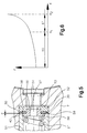
- FIG. 4 and 5 illustrate the invention Training in an axial piston machine 1 in Inclined axis designs.
- FIG Axial piston machine 1 according to the prior art in Diagonal axis construction shown, while with reference to Fig. 5, which represents a section in the area X in FIG. 4, the modification according to the invention is described.
- Fig. 4 and 5 are components that with components of FIGS. 1 to 3 are comparable, with matching reference numerals provided to facilitate the assignment.
- Inclined axis construction is a shaft 3 in a housing 2 in Rolling bearings 4 and 5 rotatably supported and by means of a Sealing 18 sealed.
- the shaft 3 has one Drive shaft flange 40, with which one in one Cylinder drum 7 center pin 42 inserted centrally is pivotally connected via a ball joint 41.
- Cylinder drum 7 In the Cylinder drum 7 are a plurality of cylinders 8 Cylinder bores formed, in which piston 9 axially are movable.
- the pistons 9 are on ball joints 43 the drive shaft flange 40 articulated.
- the housing 2 is closed by a connection block 17, in which the connections for the not shown Pressure lines.
- a connection block 17 Between the cylinder drum 7 and the connection block 17 is a lenticular trained control body 15, in which control openings 44 cyclical for connecting the pressure lines via Connection openings 12 are provided with the cylinders 8.
- the control body 15 is by means of a bolt 45 on the Terminal block 17 locked. Through the bolt 45, the Cylinder drum 7 and the central pin 42 runs in Lubrication channel for hydrostatic relief and lubrication both the ball joint 41 and the roller bearings 4 and 5 via a lubrication hole 46.
- this axial piston machine 1 in Inclined axis construction is basically based on the Axial piston machine in swash plate design, which is shown in FIG. 1 is already described problem that by the first spring 21 when the cylinder block is displaced 7 compared to the control body 15 Restoring force linear from the displacement of the Cylinder drum 7 is dependent. As already described this is inconvenient because the Cylinder drum 7 is not sufficiently counteracted.
- FIG. 5 shows the area X in FIG. 4 enlarged under simultaneous presentation of the invention Peculiarity. Elements already described are included matching reference numerals.
- the development according to the invention consists of a Cylinder drum 7 additionally acting second spring 30 with a progressive spring characteristic such that that of the second spring 30 on the cylinder drum 7 in the direction exerted on the control body 15 spring force with the Travel that the second spring 30 when the Cylinder drum 7 experiences against the control body 15, increases disproportionately.
- the illustrated embodiment is the second spring 30 designed as a plate spring.
- the disc spring is between an end face 50 of the central pin 42 and one Floor body 52, which receives the central pin 42 Central bore 51 is inserted, clamped.
- the second spring 30 can also directly between the central pin 42 and the bottom 53 of the Central bore 51 be clamped.
- the bottom body 52 has a central one Passage opening 54 for the lubrication channel and a step 55, in which a spring plate 56 is inserted, on which the first spring 21 is supported.
- the spring plate 56 has also a central bore 57 for the lubrication channel.
- the configuration according to the invention corresponds to that in Fig. 5 shown embodiment allows only one maximum displacement a of the cylinder drum 7 to Step surface 58 of the floor body 52 with the interposition of the second spring 30 or the end face 59 directly on the End face 50 of the central pin 42 strikes.
- FIG. 6 illustrates in a diagram the spring characteristic resulting from the superposition of the spring characteristic of the first spring 21 with the spring characteristic of the second spring 30.
- the spring characteristic of the first spring 21 is at least approximately linear, while the spring characteristic of the second spring 30 is progressive.
- the linear characteristic of the first spring 21 dominates, so that the spring force F exerted on the cylinder drum 7 by the springs 21 and 30 increases essentially linearly with the displacement x of the cylinder drum 7.
- the progressive characteristic of the second spring 30 dominates and the spring force F transmitted by the springs 21 and 30 to the cylinder drum 7 increases disproportionately with increasing displacement x.
- the resulting force F when approaching the displacement x 2 , at which the second spring 30 is in its flattened block state, has an asymptote, so that the second spring 30 also has a stop function, since the flattened block state of the second spring 30 is difficult can be exceeded.
- the second spring 30 not only from a plate spring but also formed several stacked disc springs become.
- the first spring 21 can also be formed by one or more Disc springs are replaced, but then in their linear range.
Landscapes
- Engineering & Computer Science (AREA)
- Physics & Mathematics (AREA)
- Fluid Mechanics (AREA)
- Mechanical Engineering (AREA)
- General Engineering & Computer Science (AREA)
- Reciprocating Pumps (AREA)
Applications Claiming Priority (2)
| Application Number | Priority Date | Filing Date | Title |
|---|---|---|---|
| DE19857082A DE19857082A1 (de) | 1998-12-10 | 1998-12-10 | Axialkolbenmaschine |
| DE19857082 | 1998-12-10 |
Publications (3)
| Publication Number | Publication Date |
|---|---|
| EP1008749A2 true EP1008749A2 (fr) | 2000-06-14 |
| EP1008749A3 EP1008749A3 (fr) | 2000-12-06 |
| EP1008749B1 EP1008749B1 (fr) | 2005-03-02 |
Family
ID=7890671
Family Applications (1)
| Application Number | Title | Priority Date | Filing Date |
|---|---|---|---|
| EP99124140A Expired - Lifetime EP1008749B1 (fr) | 1998-12-10 | 1999-12-02 | Machine à pistons axiaux |
Country Status (2)
| Country | Link |
|---|---|
| EP (1) | EP1008749B1 (fr) |
| DE (2) | DE19857082A1 (fr) |
Cited By (1)
| Publication number | Priority date | Publication date | Assignee | Title |
|---|---|---|---|---|
| WO2012076098A1 (fr) * | 2010-12-10 | 2012-06-14 | Robert Bosch Gmbh | Système à patins de glissement et piston pour une machine à pistons axiaux |
Family Cites Families (9)
| Publication number | Priority date | Publication date | Assignee | Title |
|---|---|---|---|---|
| US3292553A (en) * | 1963-12-30 | 1966-12-20 | Sunstrand Corp | Piston return mechanism |
| US3382793A (en) * | 1965-08-09 | 1968-05-14 | Sundstrand Corp | Axial piston hydraulic unit |
| DE6609071U (de) * | 1967-07-13 | 1972-02-10 | Linde Ag | Axialkolbenmaschine mit umlaufender zylindertrommel. |
| DE1945434A1 (de) * | 1969-09-08 | 1971-03-11 | Linde Ag | Axialkolbenmaschine |
| DE2130514A1 (de) * | 1971-06-19 | 1972-12-21 | Linde Ag | Axialkolbenmaschine mit Federn,welche eine Zylindertrommel und eine Andrueckplatte gegen die jeweiligen Gegenbauteile druecken |
| DE2459083C2 (de) * | 1974-12-13 | 1983-11-17 | Linde Ag, 6200 Wiesbaden | Axialkolbenmaschine |
| US5247794A (en) * | 1990-09-11 | 1993-09-28 | Sundstrand Corporation | Cylinder block positive hold-down for cold start-up |
| DE19645580C1 (de) * | 1996-11-05 | 1998-04-02 | Brueninghaus Hydromatik Gmbh | Axialkolbenmaschine mit Dämpfungselement für die Schräg- oder Taumelscheibe |
| DE19653165C2 (de) * | 1996-12-19 | 2002-04-25 | Brueninghaus Hydromatik Gmbh | Verstelleinrichtung zur Verstellung des Fördervolumens einer Axialkolbenpumpe |
-
1998
- 1998-12-10 DE DE19857082A patent/DE19857082A1/de not_active Withdrawn
-
1999
- 1999-12-02 EP EP99124140A patent/EP1008749B1/fr not_active Expired - Lifetime
- 1999-12-02 DE DE59911692T patent/DE59911692D1/de not_active Expired - Lifetime
Cited By (1)
| Publication number | Priority date | Publication date | Assignee | Title |
|---|---|---|---|---|
| WO2012076098A1 (fr) * | 2010-12-10 | 2012-06-14 | Robert Bosch Gmbh | Système à patins de glissement et piston pour une machine à pistons axiaux |
Also Published As
| Publication number | Publication date |
|---|---|
| DE59911692D1 (de) | 2005-04-07 |
| EP1008749A3 (fr) | 2000-12-06 |
| EP1008749B1 (fr) | 2005-03-02 |
| DE19857082A1 (de) | 2000-06-21 |
Similar Documents
| Publication | Publication Date | Title |
|---|---|---|
| EP0162238B1 (fr) | Machine à pistons axiaux, en particulier pompe du type à plateau incliné | |
| DE4311997C2 (de) | Hydraulikmotor | |
| EP2179175A1 (fr) | Machine à piston axial du type à plateau oscillant, présentant un dispositif de réglage | |
| DE3621421C1 (de) | Kolbenmaschine | |
| DE3340333C1 (de) | Taumelscheiben-Axialkolbenpumpe | |
| DE2914334A1 (de) | Stroemungsmittel-betaetigter stelltrieb | |
| DE19706263C1 (de) | Axialkolbenmaschine mit drehzahlabhängiger Anpressung der Zylindertrommel | |
| EP1110017B1 (fr) | ELEMENT D'ETANCHEITE A FAIBLE FROTTEMENT et cylindre hydraulique | |
| DE3632906A1 (de) | Deformationsregelwalze | |
| DE29711184U1 (de) | Hydro-Spannelement | |
| DE2403173B2 (de) | Doppelgleitringdichtung | |
| DD297690A5 (de) | Dichtungsanordnung | |
| DE4104712C2 (de) | Radialkolbenmaschine mit mechanischer Bremseinrichtung | |
| EP1008749A2 (fr) | Machine à pistons axiaux | |
| DE19645464B4 (de) | Mechanische Presse | |
| DE1812635A1 (de) | Radialkolbenpumpe | |
| DE3725156C2 (fr) | ||
| DE4217164C2 (de) | Arbeitszylinder mit Brems- oder/und Klemmeinrichtung | |
| DE2209939C3 (de) | Hydraulmotor mit Flachschieber | |
| DE3644429C2 (fr) | ||
| DE2430119C3 (de) | Hydrostatische Radialkolbenmaschine | |
| EP0344183A1 (fr) | Accouplement d'arbre a commande mecanique. | |
| DE102019215159B4 (de) | Stellkolben und Verstelleinrichtung | |
| DE19914268C2 (de) | Axialkolbenmaschine und Steuerkörper für eine Axialkolbenmaschine | |
| DE102024204681A1 (de) | Axialkolbenmaschine |
Legal Events
| Date | Code | Title | Description |
|---|---|---|---|
| PUAI | Public reference made under article 153(3) epc to a published international application that has entered the european phase |
Free format text: ORIGINAL CODE: 0009012 |
|
| AK | Designated contracting states |
Kind code of ref document: A2 Designated state(s): DE FR GB IT SE |
|
| AX | Request for extension of the european patent |
Free format text: AL;LT;LV;MK;RO;SI |
|
| PUAL | Search report despatched |
Free format text: ORIGINAL CODE: 0009013 |
|
| AK | Designated contracting states |
Kind code of ref document: A3 Designated state(s): AT BE CH CY DE DK ES FI FR GB GR IE IT LI LU MC NL PT SE |
|
| AX | Request for extension of the european patent |
Free format text: AL;LT;LV;MK;RO;SI |
|
| 17P | Request for examination filed |
Effective date: 20010112 |
|
| AKX | Designation fees paid |
Free format text: DE FR GB IT SE |
|
| 17Q | First examination report despatched |
Effective date: 20031024 |
|
| GRAP | Despatch of communication of intention to grant a patent |
Free format text: ORIGINAL CODE: EPIDOSNIGR1 |
|
| GRAS | Grant fee paid |
Free format text: ORIGINAL CODE: EPIDOSNIGR3 |
|
| GRAA | (expected) grant |
Free format text: ORIGINAL CODE: 0009210 |
|
| AK | Designated contracting states |
Kind code of ref document: B1 Designated state(s): DE FR GB IT SE |
|
| REG | Reference to a national code |
Ref country code: GB Ref legal event code: FG4D Free format text: NOT ENGLISH |
|
| GBT | Gb: translation of ep patent filed (gb section 77(6)(a)/1977) |
Effective date: 20050302 |
|
| REF | Corresponds to: |
Ref document number: 59911692 Country of ref document: DE Date of ref document: 20050407 Kind code of ref document: P |
|
| REG | Reference to a national code |
Ref country code: SE Ref legal event code: TRGR |
|
| PLBE | No opposition filed within time limit |
Free format text: ORIGINAL CODE: 0009261 |
|
| STAA | Information on the status of an ep patent application or granted ep patent |
Free format text: STATUS: NO OPPOSITION FILED WITHIN TIME LIMIT |
|
| ET | Fr: translation filed | ||
| 26N | No opposition filed |
Effective date: 20051205 |
|
| PGFP | Annual fee paid to national office [announced via postgrant information from national office to epo] |
Ref country code: GB Payment date: 20121218 Year of fee payment: 14 Ref country code: SE Payment date: 20121217 Year of fee payment: 14 Ref country code: IT Payment date: 20121220 Year of fee payment: 14 |
|
| PGFP | Annual fee paid to national office [announced via postgrant information from national office to epo] |
Ref country code: FR Payment date: 20130123 Year of fee payment: 14 |
|
| REG | Reference to a national code |
Ref country code: SE Ref legal event code: EUG |
|
| GBPC | Gb: european patent ceased through non-payment of renewal fee |
Effective date: 20131202 |
|
| PG25 | Lapsed in a contracting state [announced via postgrant information from national office to epo] |
Ref country code: SE Free format text: LAPSE BECAUSE OF NON-PAYMENT OF DUE FEES Effective date: 20131203 |
|
| REG | Reference to a national code |
Ref country code: FR Ref legal event code: ST Effective date: 20140829 |
|
| PG25 | Lapsed in a contracting state [announced via postgrant information from national office to epo] |
Ref country code: FR Free format text: LAPSE BECAUSE OF NON-PAYMENT OF DUE FEES Effective date: 20131231 Ref country code: GB Free format text: LAPSE BECAUSE OF NON-PAYMENT OF DUE FEES Effective date: 20131202 |
|
| PG25 | Lapsed in a contracting state [announced via postgrant information from national office to epo] |
Ref country code: IT Free format text: LAPSE BECAUSE OF NON-PAYMENT OF DUE FEES Effective date: 20131231 |
|
| PGFP | Annual fee paid to national office [announced via postgrant information from national office to epo] |
Ref country code: DE Payment date: 20160224 Year of fee payment: 17 |
|
| PG25 | Lapsed in a contracting state [announced via postgrant information from national office to epo] |
Ref country code: IT Free format text: LAPSE BECAUSE OF NON-PAYMENT OF DUE FEES Effective date: 20131202 |
|
| REG | Reference to a national code |
Ref country code: DE Ref legal event code: R119 Ref document number: 59911692 Country of ref document: DE |
|
| PG25 | Lapsed in a contracting state [announced via postgrant information from national office to epo] |
Ref country code: DE Free format text: LAPSE BECAUSE OF NON-PAYMENT OF DUE FEES Effective date: 20170701 |