EP1008755A1 - Machine à rotors à vis - Google Patents
Machine à rotors à vis Download PDFInfo
- Publication number
- EP1008755A1 EP1008755A1 EP99630089A EP99630089A EP1008755A1 EP 1008755 A1 EP1008755 A1 EP 1008755A1 EP 99630089 A EP99630089 A EP 99630089A EP 99630089 A EP99630089 A EP 99630089A EP 1008755 A1 EP1008755 A1 EP 1008755A1
- Authority
- EP
- European Patent Office
- Prior art keywords
- rotors
- pair
- circle
- rotor
- clearance
- Prior art date
- Legal status (The legal status is an assumption and is not a legal conclusion. Google has not performed a legal analysis and makes no representation as to the accuracy of the status listed.)
- Granted
Links
- 238000013459 approach Methods 0.000 claims description 5
- 230000013011 mating Effects 0.000 claims 18
- 238000007789 sealing Methods 0.000 claims 1
- 238000009826 distribution Methods 0.000 abstract description 21
- 238000004519 manufacturing process Methods 0.000 description 7
- 230000004048 modification Effects 0.000 description 6
- 238000012986 modification Methods 0.000 description 6
- 238000007906 compression Methods 0.000 description 4
- 230000007423 decrease Effects 0.000 description 4
- 239000007787 solid Substances 0.000 description 3
- 230000006835 compression Effects 0.000 description 2
- 230000000694 effects Effects 0.000 description 2
- 238000003754 machining Methods 0.000 description 2
- 239000000463 material Substances 0.000 description 2
- 230000007246 mechanism Effects 0.000 description 2
- 238000005096 rolling process Methods 0.000 description 2
- 230000008859 change Effects 0.000 description 1
- 238000007689 inspection Methods 0.000 description 1
- 230000009467 reduction Effects 0.000 description 1
- 238000004513 sizing Methods 0.000 description 1
Images
Classifications
-
- F—MECHANICAL ENGINEERING; LIGHTING; HEATING; WEAPONS; BLASTING
- F01—MACHINES OR ENGINES IN GENERAL; ENGINE PLANTS IN GENERAL; STEAM ENGINES
- F01C—ROTARY-PISTON OR OSCILLATING-PISTON MACHINES OR ENGINES
- F01C1/00—Rotary-piston machines or engines
- F01C1/08—Rotary-piston machines or engines of intermeshing engagement type, i.e. with engagement of co- operating members similar to that of toothed gearing
-
- F—MECHANICAL ENGINEERING; LIGHTING; HEATING; WEAPONS; BLASTING
- F04—POSITIVE - DISPLACEMENT MACHINES FOR LIQUIDS; PUMPS FOR LIQUIDS OR ELASTIC FLUIDS
- F04C—ROTARY-PISTON, OR OSCILLATING-PISTON, POSITIVE-DISPLACEMENT MACHINES FOR LIQUIDS; ROTARY-PISTON, OR OSCILLATING-PISTON, POSITIVE-DISPLACEMENT PUMPS
- F04C18/00—Rotary-piston pumps specially adapted for elastic fluids
- F04C18/08—Rotary-piston pumps specially adapted for elastic fluids of intermeshing-engagement type, i.e. with engagement of co-operating members similar to that of toothed gearing
- F04C18/082—Details specially related to intermeshing engagement type pumps
- F04C18/084—Toothed wheels
-
- Y—GENERAL TAGGING OF NEW TECHNOLOGICAL DEVELOPMENTS; GENERAL TAGGING OF CROSS-SECTIONAL TECHNOLOGIES SPANNING OVER SEVERAL SECTIONS OF THE IPC; TECHNICAL SUBJECTS COVERED BY FORMER USPC CROSS-REFERENCE ART COLLECTIONS [XRACs] AND DIGESTS
- Y10—TECHNICAL SUBJECTS COVERED BY FORMER USPC
- Y10T—TECHNICAL SUBJECTS COVERED BY FORMER US CLASSIFICATION
- Y10T74/00—Machine element or mechanism
- Y10T74/19—Gearing
- Y10T74/19949—Teeth
- Y10T74/19953—Worm and helical
Definitions
- the profile design of a conjugate pair of screw rotors starts with zero clearance profiles which satisfy all conjugacy requirements and do not have any gap between the male and female rotors at any conjugate point.
- the design is then modified to include a clearance resulting in clearance profiles.
- the modifications are in the direction normal to the rotor profile at any given point and can vary from point-to-point.
- the need to provide a clearance is the result of a number of factors including: thermal growth of the rotors as a result of gas being heated in the compression process; deflection of the rotors due to pressure loading resulting from the compression process; tolerances in the support bearing structure and machining tolerances on the rotors which may sometimes tend to locate the rotors too close to one another which can lead to interference; and machining tolerances on the rotor profiles themselves which can also lead to interference.
- superimposed upon these factors is the existence of pressure and thermal gradients as the pressure and temperature increase in going from suction to discharge.
- the zero clearance profile coordinates are modified before manufacturing the rotors. If zero clearance profiles are manufactured and put in an operating compressor, it will result in interference between the rotors due to some or all of the foregoing reasons, causing excessive wear and high bearing loads, if the compressor can even operate at all. Clearance profiles introduce leakage as the price of reducing wear and bearing loads since a zero clearance profile has no leakage area through the seal line of the mesh zone of the rotors. The leakage through the clearance area of the seal line will flow directly from the compression chamber back to the compressor suction and thus tends to be a more severe leak than, for example, leakage across the tip clearance or through the blow hole, both of which tend to be between successive compression chambers.
- thermal growth it is estimated based upon the size and material of the rotors and the design operating temperature of the compressor.
- the associated clearances should be such that when maximum expected thermal growth occurs, there is no unwanted interference between the rotors.
- deflection it is a function of the loading and stiffness characteristics of the rotors and of the support bearing structure.
- the pressure loading on the rotors is determined from the operating characteristics of the compressor application. Stiffness characteristics of the rotors are determined from their size and material as well as the supporting mechanism.
- the associated clearances are selected such that there is no unwanted contact at maximum deflections.
- the associated clearances of the rotors are determined by the capabilities of the respective manufacturing processes for the rotors, supporting mechanism, and locating features.
- the associated clearances are selected such that there is no unwanted contact at maximum tolerance deviations. All of these various factors are considered in determining the total amount of clearance to be introduced between the rotors.
- the typically maximum clearance requirements can be determined for selected key points.
- the next step according to the teachings of the present invention is to achieve a reduced leakage area while still having required clearances to produce functional screw rotor profiles.
- the clearance requirement for functional screw rotor profiles at these points can be determined based on the requirements of manufacturing tolerances, deflection, thermal growth, etc.
- the segment of the rotor defining the contact band is the region where the required torque is transmitted between the rotors. These segments are positioned near the pitch circles of the rotors which is the location of equal rotational speed on the rotors resulting in rolling contact and thereby in less wear. As contact starts to move away from the pitch circle there is more sliding contact rather than pure rolling contact which would result in more wear if the contact band were to be located away from the pitch circle.
- the backlash zone is positioned near the pitch circle on the opposite side of the screw rotor lobes from the contact zone.
- the controlled clearance of the backlash zone prevents too tight of a fit between the two rotors which might otherwise cause binding and wear while at the same time limiting the space available for the rotors to rattle or impact each other through the backlash clearance which might otherwise result in objectionable noise and/or vibration.
- the four zones constitute portions where a specific, well-defined clearance or clearance range is established separately for each portion.
- a quadradic, cubic or higher order distribution can be used to vary the clearances while reducing the leakage area defined by the clearances since such distributions initially reduce the clearances more rapidly than a linear distribution, leaving smaller clearances over the rest of the profile between the two points. It should be noted that distribution of clearance should be smooth to accommodate manufacturing processes with no steps allowed.
- zero clearance screw rotor profiles are modified by determining clearance requirements at spaced points on the profiles and varying the clearance distribution between adjacent points using a non-linear distribution. Additionally, when the clearances are put in the rotors, zero clearance is maintained between the rotors in the contact band which is maintained near the pitch circle.
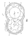
- the numeral 10 generally indicates a screw machine such as a screw compressor.
- Screw machine 10 has a casing 12 with overlapping bores 12-1 and 12-2 located therein.
- Female rotor 14 has a pitch circle, P F , and is located in bore 12-1.
- Male rotor 16 has a pitch circle, P M , and is located in bore 12-2.
- the axes indicated by points X and Y are perpendicular to the plane of Figure 1 and are parallel to each other and are separated by a distance equal to the sum of the radius, R PF of the pitch circle, P F , of female rotor 14 and the radius, R PM , of the pitch circle, P M , of male rotor 16.
- the axis indicated by point X is the axis of rotation of female rotor 14 and the center of bore 12-1 whose diameter generally corresponds to the diameter of the tip circle, T F , of female rotor 14.
- the axis indicated by point Y is the axis of rotation of male rotor 16 and the center of bore 12-2 whose diameter generally corresponds to the diameter of the tip circle, T M , of male rotor 16.
- female rotor 14 has six tips, represented by co-located points P and U, separated by six grooves, the bases of which are represented by points R, while male rotor 16 has five lands, represented by points M, separated by five grooves, the bases of which are represented by co-located points O and K. Accordingly, the rotational speed of rotor 16 will be 6/5 or 120% of that of rotor 14. When the rotors are thus rotated, the velocity of any two points on the respective pitch circles are the same and the rotors are said to rotate at the same pitch circle velocity. Either the female rotor 14 or the male rotor 16 may be connected to a prime mover (not illustrated) and serve as the driving rotor. Other combinations of the number of female and male lands and grooves may also be used.
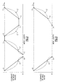
- the solid line A-B-C-D-E-F-G-H-I represents the PRIOR ART clearance between an assembled pair of conjugate rotors extending from a point, A, on one lobe to a corresponding point, I, on an adjacent lobe.
- the clearance represented by the area under the solid line A-B-C-D-E-F-G-H-I represents the leakage area.
- the PRIOR ART plot is a series of straight lines and is reflective of a linear distribution of clearances. A portion, B-C, of the plot is on the zero clearance line and represents the contact band where zero clearance is desired.
- a second portion, F-G, of the plot is generally of a uniform clearance and represents the backlash zone which is the area of driving contact upon powered reverse rotation or of intermittent contact in a rattling or chatter situation. Where reverse rotation is the result of pressure equalization, as at shut down, contact remains with the contact band.
- the dashed lines A-A'-B, C-C'-D, E-E'-F, and G-G'-H, in Figure 2 represent the modified clearance distribution resulting from the application of the teachings of the present invention. It is clear that the dashed lines represent a reduction in the leakage area which will correspond to an increase in compressor efficiency. It should be noted that the present invention provides an alternative clearance distribution between points common with the PRIOR ART and that the contact band B-C, male tip/female root D-E, backlash zone F-G, and female tip/male root H-I are nominally the same for the PRIOR ART and the present invention.
- Figure 2 illustrates the clearance distribution between the two rotors.
- the horizontal axis of Figures 2-4 represents the linear distance along the lobe or rotor profile, i.e. as if you held each end and "pulled it out straight". While the clearances are located on both rotors, the clearance between the rotors may be removed from a single rotor for segments of the clearance.
- Figures 3 and 4 show the portion of the clearance in Figure 2 provided by the male and female rotors, respectively.
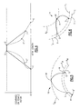
- Figures 5 and 6 illustrate the modification to the zero clearance profiles to achieve the clearances of Figures 3 and 4, respectively. Specifically, in Figure 5, the solid profile K-L-M-N-O, represents the zero clearance profile of the male rotor.
- the dashed segments K'-L and N-O' represent the clearance profile modifications to the male rotor according to the teachings of the present invention and corresponding to dashed segments A-A'-B and G-G'-H, respectively, of Figure 3.
- the solid profile P-Q-R-S-T represents the zero clearance profile of the female rotor.
- the dashed segment Q-R'-S represents the clearance profile modifications to the female rotor according to the teachings of the present invention.
- the screw rotor clearance distribution starts with specifying the clearance at four key zones, namely: (1) the male tip/female root represented by D-E; (2) the backlash zone represented by F-G; (3) the female tip/male root represented by H-I; and (4) the contact band B-C which always has a zero clearance.
- the clearance at the four key zones is the same for the PRIOR ART profile and in the profile of the present invention.
- Defining the clearances includes specifying the boundaries as you go along the profile.
- the end or boundary points of the specified clearance portions, as defined in Figure 2 represent fixed points that must be connected.
- a linear distribution was assigned between the end points defined by the specified clearances, i.e. a straight line was drawn between adjacent points in Figure 2.
- curves are used in place of straight lines to connect the areas of specified clearances.
- These curves can be quadratic curves, cubic curves, sinusoids, or some other high order curve. Specific guidelines or rules for selecting these curves and their characteristics include:
- the curve should "fall away” rapidly at first, as in the nature of a catenary, so that the clearance decreases rapidly to avoid having wide zones near the tips/roots with similarly high clearances.
- the rate of decrease will be more rapid or steep than for a linear distribution.
- the curve should begin to level out at some clearance value which is reasonably controllable in manufacturing as in the vicinity of points A' and C' in Figure 2. Stated otherwise, its value will be influenced most heavily by manufacturing tolerances. Defining the "degree of steepness” as being characterized by the angle between a radial line through a point on the surface and the surface with smaller values of the angle being "steeper” and defining “flatness” as being characterized by the degree of perpendicularity of the surface to a radial line through a point on the surface with more perpendicular surfaces being “shallower", where the slope of the lobe surface is relatively steep, rotor deflections will result in relatively small changes in operating clearances as compared to the flat tip and root regions.
- this property of the clearance curves A-A'-B and C-C'-D between the tip/root and contact band B-C results in an S-shape, more complex than the conventional straight line or even a quadratic curve.
- This S-shape may be formed of two different quadrates or of a single curve of higher order.
- the ultimate objective is to achieve the total clearance distribution throughout the total engagement.
- clearance may be built into either the male rotor 16 or the female rotor 14 lobe geometry.
- Zero clearance profiles are usually designed with integral tip and root circle diameters, e.g. 90.0 mm and 104.0 mm.
- the male tip circle is T M
- the male pitch circle is P M
- the male root circle is R M
- female tip circle is T F
- the female pitch circle is P F
- the female root circle is R F .
- the diameters of tip circles T M and T F are more easily controlled and inspected and their nominal value is the basis for sizing the rotor bore diameters and bearing bore alignment specifications.
Landscapes
- Engineering & Computer Science (AREA)
- Mechanical Engineering (AREA)
- General Engineering & Computer Science (AREA)
- Applications Or Details Of Rotary Compressors (AREA)
- Rotary Pumps (AREA)
Applications Claiming Priority (2)
| Application Number | Priority Date | Filing Date | Title |
|---|---|---|---|
| US09/208,866 US6167771B1 (en) | 1998-12-10 | 1998-12-10 | Clearance distribution to reduce the leakage area |
| US208866 | 1998-12-10 |
Publications (2)
| Publication Number | Publication Date |
|---|---|
| EP1008755A1 true EP1008755A1 (fr) | 2000-06-14 |
| EP1008755B1 EP1008755B1 (fr) | 2005-03-09 |
Family
ID=22776357
Family Applications (1)
| Application Number | Title | Priority Date | Filing Date |
|---|---|---|---|
| EP99630089A Expired - Lifetime EP1008755B1 (fr) | 1998-12-10 | 1999-11-19 | Machine à rotors à vis |
Country Status (9)
| Country | Link |
|---|---|
| US (1) | US6167771B1 (fr) |
| EP (1) | EP1008755B1 (fr) |
| JP (1) | JP3483818B2 (fr) |
| KR (1) | KR100362984B1 (fr) |
| CN (1) | CN1133011C (fr) |
| AU (1) | AU738697B2 (fr) |
| DE (1) | DE69924079T2 (fr) |
| ES (1) | ES2239836T3 (fr) |
| TW (1) | TW517137B (fr) |
Cited By (4)
| Publication number | Priority date | Publication date | Assignee | Title |
|---|---|---|---|---|
| GB2401401A (en) * | 2003-05-08 | 2004-11-10 | Automotive Motion Tech Ltd | Three rotor screw pump with smaller central rotor |
| US7232297B2 (en) | 2003-05-08 | 2007-06-19 | Automotive Motion Technology Limited | Screw pump |
| US7234925B2 (en) | 2004-11-08 | 2007-06-26 | Automotive Motion Technology Limited | Screw pump |
| CN1746462B (zh) * | 2004-09-10 | 2010-09-01 | 复盛股份有限公司 | 螺旋转子机构 |
Families Citing this family (12)
| Publication number | Priority date | Publication date | Assignee | Title |
|---|---|---|---|---|
| AU2003902704A0 (en) * | 2003-05-29 | 2003-06-19 | Crc For Waste Management And Pollution Control Limited Of Unsw | Process for producing a nanoscale zero-valent metal |
| US7156624B2 (en) * | 2004-12-09 | 2007-01-02 | Carrier Corporation | Compressor sound suppression |
| JP4760474B2 (ja) * | 2006-03-28 | 2011-08-31 | 株式会社日立プラントテクノロジー | スクリュー流体機械 |
| JP2012207660A (ja) * | 2011-03-11 | 2012-10-25 | Toyota Industries Corp | スクリュポンプ |
| GB2501302B (en) * | 2012-04-19 | 2016-08-31 | The City Univ | Reduced noise screw machines |
| CN104235019B (zh) * | 2013-06-19 | 2016-08-31 | 株式会社日立产机系统 | 螺旋式压缩机 |
| KR20250117556A (ko) | 2024-01-27 | 2025-08-05 | 변희주 | 하비비 |
| KR20250117557A (ko) | 2024-01-27 | 2025-08-05 | 김예진 | 개인 냉장고 식재료 데이터 기반 맞춤형 음식 레시피 제공 방법 및 식재료 관리 시스템 |
| KR20250167988A (ko) | 2024-05-23 | 2025-12-02 | 대동대학교 산학협력단 | 빠삭빠삭 기장멸치 누룽지빵 |
| KR20260069870A (ko) | 2024-11-08 | 2026-05-18 | 성기성 | 휴대용 ai 체성분 분석 및 운동 보조 기기 |
| KR20260078600A (ko) | 2024-11-22 | 2026-05-29 | 한혜연 | Vr 메이크업 가상 체험 방법 |
| KR20260078617A (ko) | 2024-11-22 | 2026-05-29 | 최수진 | 레몬생강청 견과류 비빔소스 |
Citations (5)
| Publication number | Priority date | Publication date | Assignee | Title |
|---|---|---|---|---|
| JPS5958189A (ja) * | 1982-09-27 | 1984-04-03 | Hitachi Ltd | スクリユ−ロ−タ |
| EP0194444A2 (fr) * | 1985-03-04 | 1986-09-17 | Hitachi, Ltd. | Profil des dents pour rotor à vis |
| DE2953832C1 (de) * | 1979-03-23 | 1987-11-12 | Gutehoffnungshuette Man | Schraubenrotormaschine |
| EP0308055A2 (fr) * | 1987-09-01 | 1989-03-22 | Kabushiki Kaisha Kobe Seiko Sho | Assemblage de rotors pour compresseur à vis |
| EP0591979A1 (fr) * | 1992-10-09 | 1994-04-13 | Mayekawa Mfg Co.Ltd. | Profil des dents pour rotor à vis |
Family Cites Families (5)
| Publication number | Priority date | Publication date | Assignee | Title |
|---|---|---|---|---|
| US4673344A (en) * | 1985-12-16 | 1987-06-16 | Ingalls Robert A | Screw rotor machine with specific lobe profiles |
| JP2703323B2 (ja) * | 1989-03-24 | 1998-01-26 | 株式会社神戸製鋼所 | スクリュ式ポンプ装置用スクリュロータ |
| SE508087C2 (sv) * | 1996-12-16 | 1998-08-24 | Svenska Rotor Maskiner Ab | Par av samverkande skruvrotorer, skruvrotor samt skruvrotormaskin försedd med dylika skruvrotorer |
| US6139299A (en) * | 1998-05-29 | 2000-10-31 | Carrier Corporation | Conjugate screw rotor profile |
| US9127553B2 (en) | 2012-04-13 | 2015-09-08 | General Electric Company | Method, systems, and apparatuses for transition piece contouring |
-
1998
- 1998-12-10 US US09/208,866 patent/US6167771B1/en not_active Expired - Lifetime
-
1999
- 1999-11-18 TW TW088120160A patent/TW517137B/zh not_active IP Right Cessation
- 1999-11-19 EP EP99630089A patent/EP1008755B1/fr not_active Expired - Lifetime
- 1999-11-19 DE DE69924079T patent/DE69924079T2/de not_active Expired - Lifetime
- 1999-11-19 ES ES99630089T patent/ES2239836T3/es not_active Expired - Lifetime
- 1999-11-30 CN CN99125860A patent/CN1133011C/zh not_active Expired - Fee Related
- 1999-12-03 JP JP34431299A patent/JP3483818B2/ja not_active Expired - Fee Related
- 1999-12-03 KR KR1019990054726A patent/KR100362984B1/ko not_active Expired - Fee Related
- 1999-12-09 AU AU64431/99A patent/AU738697B2/en not_active Ceased
Patent Citations (5)
| Publication number | Priority date | Publication date | Assignee | Title |
|---|---|---|---|---|
| DE2953832C1 (de) * | 1979-03-23 | 1987-11-12 | Gutehoffnungshuette Man | Schraubenrotormaschine |
| JPS5958189A (ja) * | 1982-09-27 | 1984-04-03 | Hitachi Ltd | スクリユ−ロ−タ |
| EP0194444A2 (fr) * | 1985-03-04 | 1986-09-17 | Hitachi, Ltd. | Profil des dents pour rotor à vis |
| EP0308055A2 (fr) * | 1987-09-01 | 1989-03-22 | Kabushiki Kaisha Kobe Seiko Sho | Assemblage de rotors pour compresseur à vis |
| EP0591979A1 (fr) * | 1992-10-09 | 1994-04-13 | Mayekawa Mfg Co.Ltd. | Profil des dents pour rotor à vis |
Non-Patent Citations (1)
| Title |
|---|
| PATENT ABSTRACTS OF JAPAN vol. 008, no. 164 (M - 313) 28 July 1984 (1984-07-28) * |
Cited By (5)
| Publication number | Priority date | Publication date | Assignee | Title |
|---|---|---|---|---|
| GB2401401A (en) * | 2003-05-08 | 2004-11-10 | Automotive Motion Tech Ltd | Three rotor screw pump with smaller central rotor |
| US7232297B2 (en) | 2003-05-08 | 2007-06-19 | Automotive Motion Technology Limited | Screw pump |
| US7452194B2 (en) | 2003-05-08 | 2008-11-18 | Buhler Motor Gmbh | Screw pump |
| CN1746462B (zh) * | 2004-09-10 | 2010-09-01 | 复盛股份有限公司 | 螺旋转子机构 |
| US7234925B2 (en) | 2004-11-08 | 2007-06-26 | Automotive Motion Technology Limited | Screw pump |
Also Published As
| Publication number | Publication date |
|---|---|
| CN1133011C (zh) | 2003-12-31 |
| AU738697B2 (en) | 2001-09-27 |
| EP1008755B1 (fr) | 2005-03-09 |
| CN1256365A (zh) | 2000-06-14 |
| KR20000047895A (ko) | 2000-07-25 |
| JP3483818B2 (ja) | 2004-01-06 |
| DE69924079D1 (de) | 2005-04-14 |
| ES2239836T3 (es) | 2005-10-01 |
| AU6443199A (en) | 2000-06-29 |
| US6167771B1 (en) | 2001-01-02 |
| TW517137B (en) | 2003-01-11 |
| DE69924079T2 (de) | 2005-08-11 |
| KR100362984B1 (ko) | 2002-11-29 |
| JP2000170675A (ja) | 2000-06-20 |
Similar Documents
| Publication | Publication Date | Title |
|---|---|---|
| EP1008755B1 (fr) | Machine à rotors à vis | |
| US7153111B2 (en) | Screw machine | |
| AU2002237937B2 (en) | Method to rough size coated components for easy assembly | |
| US12448968B2 (en) | Low coefficient of expansion rotors for blowers | |
| AU2002237937A1 (en) | Method to rough size coated components for easy assembly | |
| EP0961009B1 (fr) | Profil de rotor à vis conjugué | |
| US6283734B1 (en) | Gear pump and a method for positioning a gear pump shaft | |
| US20030126733A1 (en) | Method to rough size coated components for easy assembly | |
| WO2013156754A1 (fr) | Machines à vis à bruit réduit | |
| CN110848137A (zh) | 一种零间隙螺杆转子及其制备方法 | |
| AU2003257923B2 (en) | Conjugate screw rotor profile |
Legal Events
| Date | Code | Title | Description |
|---|---|---|---|
| PUAI | Public reference made under article 153(3) epc to a published international application that has entered the european phase |
Free format text: ORIGINAL CODE: 0009012 |
|
| AK | Designated contracting states |
Kind code of ref document: A1 Designated state(s): DE ES FR GB IT NL |
|
| AX | Request for extension of the european patent |
Free format text: AL;LT;LV;MK;RO;SI |
|
| 17P | Request for examination filed |
Effective date: 20001116 |
|
| AKX | Designation fees paid |
Free format text: DE ES FR GB IT NL |
|
| 17Q | First examination report despatched |
Effective date: 20030717 |
|
| GRAP | Despatch of communication of intention to grant a patent |
Free format text: ORIGINAL CODE: EPIDOSNIGR1 |
|
| GRAS | Grant fee paid |
Free format text: ORIGINAL CODE: EPIDOSNIGR3 |
|
| GRAA | (expected) grant |
Free format text: ORIGINAL CODE: 0009210 |
|
| AK | Designated contracting states |
Kind code of ref document: B1 Designated state(s): DE ES FR GB IT NL |
|
| REG | Reference to a national code |
Ref country code: GB Ref legal event code: FG4D |
|
| REF | Corresponds to: |
Ref document number: 69924079 Country of ref document: DE Date of ref document: 20050414 Kind code of ref document: P |
|
| REG | Reference to a national code |
Ref country code: ES Ref legal event code: FG2A Ref document number: 2239836 Country of ref document: ES Kind code of ref document: T3 |
|
| PLBE | No opposition filed within time limit |
Free format text: ORIGINAL CODE: 0009261 |
|
| STAA | Information on the status of an ep patent application or granted ep patent |
Free format text: STATUS: NO OPPOSITION FILED WITHIN TIME LIMIT |
|
| 26N | No opposition filed |
Effective date: 20051212 |
|
| ET | Fr: translation filed | ||
| PGFP | Annual fee paid to national office [announced via postgrant information from national office to epo] |
Ref country code: NL Payment date: 20061006 Year of fee payment: 8 |
|
| NLV4 | Nl: lapsed or anulled due to non-payment of the annual fee |
Effective date: 20080601 |
|
| PG25 | Lapsed in a contracting state [announced via postgrant information from national office to epo] |
Ref country code: NL Free format text: LAPSE BECAUSE OF NON-PAYMENT OF DUE FEES Effective date: 20080601 |
|
| PG25 | Lapsed in a contracting state [announced via postgrant information from national office to epo] |
Ref country code: IT Free format text: LAPSE BECAUSE OF NON-PAYMENT OF DUE FEES Effective date: 20111119 |
|
| PGFP | Annual fee paid to national office [announced via postgrant information from national office to epo] |
Ref country code: IT Payment date: 20111119 Year of fee payment: 13 |
|
| PGRI | Patent reinstated in contracting state [announced from national office to epo] |
Ref country code: IT Effective date: 20130510 |
|
| PGRI | Patent reinstated in contracting state [announced from national office to epo] |
Ref country code: IT Effective date: 20130510 |
|
| REG | Reference to a national code |
Ref country code: FR Ref legal event code: PLFP Year of fee payment: 17 |
|
| PGFP | Annual fee paid to national office [announced via postgrant information from national office to epo] |
Ref country code: GB Payment date: 20151027 Year of fee payment: 17 Ref country code: DE Payment date: 20151022 Year of fee payment: 17 |
|
| PGFP | Annual fee paid to national office [announced via postgrant information from national office to epo] |
Ref country code: FR Payment date: 20151023 Year of fee payment: 17 Ref country code: ES Payment date: 20151110 Year of fee payment: 17 |
|
| REG | Reference to a national code |
Ref country code: DE Ref legal event code: R119 Ref document number: 69924079 Country of ref document: DE |
|
| REG | Reference to a national code |
Ref country code: DE Ref legal event code: R082 Ref document number: 69924079 Country of ref document: DE Representative=s name: SCHMITT-NILSON SCHRAUD WAIBEL WOHLFROM PATENTA, DE |
|
| GBPC | Gb: european patent ceased through non-payment of renewal fee |
Effective date: 20161119 |
|
| REG | Reference to a national code |
Ref country code: FR Ref legal event code: ST Effective date: 20170731 |
|
| PG25 | Lapsed in a contracting state [announced via postgrant information from national office to epo] |
Ref country code: FR Free format text: LAPSE BECAUSE OF NON-PAYMENT OF DUE FEES Effective date: 20161130 |
|
| PG25 | Lapsed in a contracting state [announced via postgrant information from national office to epo] |
Ref country code: GB Free format text: LAPSE BECAUSE OF NON-PAYMENT OF DUE FEES Effective date: 20161119 Ref country code: DE Free format text: LAPSE BECAUSE OF NON-PAYMENT OF DUE FEES Effective date: 20170601 |
|
| PG25 | Lapsed in a contracting state [announced via postgrant information from national office to epo] |
Ref country code: ES Free format text: LAPSE BECAUSE OF FAILURE TO SUBMIT A TRANSLATION OF THE DESCRIPTION OR TO PAY THE FEE WITHIN THE PRESCRIBED TIME-LIMIT Effective date: 20050309 |
|
| REG | Reference to a national code |
Ref country code: ES Ref legal event code: FD2A Effective date: 20181116 |
|
| PG25 | Lapsed in a contracting state [announced via postgrant information from national office to epo] |
Ref country code: ES Free format text: LAPSE BECAUSE OF FAILURE TO SUBMIT A TRANSLATION OF THE DESCRIPTION OR TO PAY THE FEE WITHIN THE PRESCRIBED TIME-LIMIT Effective date: 20161120 |