EP1008787A1 - Joint à brosse à double contact - Google Patents
Joint à brosse à double contact Download PDFInfo
- Publication number
- EP1008787A1 EP1008787A1 EP99403084A EP99403084A EP1008787A1 EP 1008787 A1 EP1008787 A1 EP 1008787A1 EP 99403084 A EP99403084 A EP 99403084A EP 99403084 A EP99403084 A EP 99403084A EP 1008787 A1 EP1008787 A1 EP 1008787A1
- Authority
- EP
- European Patent Office
- Prior art keywords
- rings
- ring
- fixed
- brush seal
- seal
- Prior art date
- Legal status (The legal status is an assumption and is not a legal conclusion. Google has not performed a legal analysis and makes no representation as to the accuracy of the status listed.)
- Granted
Links
- 230000009975 flexible effect Effects 0.000 claims abstract description 20
- 238000007789 sealing Methods 0.000 claims description 11
- 238000011144 upstream manufacturing Methods 0.000 description 15
- 239000000835 fiber Substances 0.000 description 2
- 238000004519 manufacturing process Methods 0.000 description 2
- 208000031968 Cadaver Diseases 0.000 description 1
- 230000004888 barrier function Effects 0.000 description 1
- 239000012530 fluid Substances 0.000 description 1
- 210000004209 hair Anatomy 0.000 description 1
- 238000012423 maintenance Methods 0.000 description 1
- 239000000463 material Substances 0.000 description 1
- 239000002184 metal Substances 0.000 description 1
- 238000000034 method Methods 0.000 description 1
- 238000003466 welding Methods 0.000 description 1
Images


Classifications
-
- F—MECHANICAL ENGINEERING; LIGHTING; HEATING; WEAPONS; BLASTING
- F16—ENGINEERING ELEMENTS AND UNITS; GENERAL MEASURES FOR PRODUCING AND MAINTAINING EFFECTIVE FUNCTIONING OF MACHINES OR INSTALLATIONS; THERMAL INSULATION IN GENERAL
- F16J—PISTONS; CYLINDERS; SEALINGS
- F16J15/00—Sealings
- F16J15/16—Sealings between relatively-moving surfaces
- F16J15/32—Sealings between relatively-moving surfaces with elastic sealings, e.g. O-rings
- F16J15/3284—Sealings between relatively-moving surfaces with elastic sealings, e.g. O-rings characterised by their structure; Selection of materials
- F16J15/3288—Filamentary structures, e.g. brush seals
Definitions
- the invention relates to sealing between two enclosures or volumes under pressure different and located around an axis or a tree turning. It concerns, in particular, aeronautical turbomachinery which use very frequently the type of seal, called a seal brush.
- the brush seals are located under the form of bundles of threads, fibers or strands which can be metallic, organic or synthetic.
- the choice of material is dictated by the conditions environment and operation of the brush seal, that is to say by the nature of the fluids to be sealed, by temperatures and pressures prevailing on both sides and on the other side of the joint.
- one of these types of joints allows to isolate two volumes or two enclosures A and B surrounding a rotating shaft 1.
- the wire harness 2 is preferably arranged radially with respect to this rotary shaft 1 and its end 2E touches the outer surface of the shaft rotary 1.
- the wire harness 2 is mounted in a fixed support 3 which constitutes the support for the seal.
- an upstream ring 5 placed upstream of the wire harness 2 and positioned by means of a ring fixing 7, itself fixed in the seal support 3.
- a downstream ring 6 fixed downstream of the bundle of wires 2 and placed in abutment against a rib 4 of the joint support 3.
- downstream ring 6 has a smaller inner diameter than the upstream ring 5.
- the downstream ring supports the beam over a longer length of wires 2 as the upstream ring 5.
- the end 2E of the bundle 2 therefore enjoys a certain freedom, especially on the upstream side, i.e. the upstream ring 2. We thus delimit two regions well separated by the joint and in which there may be pressures different.
- Brush seals can also be arranged axially, for example in the frame semi-static applications, or to equip a slave axial seal. In this case, the implementation of classical techniques used in the design of metal radial seals is impossible.
- the purpose of this invention is to provide double axial brush seal design sealing barrier, this design is also applicable to radial seals, even if the mounting of the joint is more complex.
- the two flexible sealing bundles consist of a single flexible shaped ribbon of U whose central part is fixed in the body of maintenance.
- the holding body is formed by two rings, a ring inside and an outside ring, both shaped like U and overlapping each other.
- the branches of the two U-shaped rings are not the same length, so the end of each beam seal is in contact with only one ring.
- the upstream branch 26 of the outer ring 25 is longer than the branch downstream 27 of the latter.
- the upstream branch 21 of the inner ring 20 is smaller than the branch downstream 22 of the latter. Therefore, each of the two ends 31 and 32 of the flexible tape 30 constituting the two sealing bundles of the joint are not each contact with only one wall of a ring, either inside 20 or outside 25. So, the upstream end 31 of the flexible tape 30 is in contact with the upstream end 26 of the outer ring 25 and the downstream end 32 of the flexible tape 30 is in contact with the external surface of the downstream end 22 of the inner ring 20.
- Each end 31 and 32 of the flexible tape 30 therefore benefits from a freedom of relatively large movement, especially on the downstream side, in this realization.
- the extremities longer i.e. the upstream end 26 of the outer ring and the downstream end 22 of the ring interior 20, are relatively close to the surface of the rotary shaft 1 to limit the freedom of movement of the two ends 31 and 32 of the ribbon flexible on the upstream side.
- the parties long or long branches 22 and 26 of the rings inside 20 and outside 25 are placed in opposition to guide the hairs or fibers constituting the flexible tape brush as close as possible to the contact with the surface of the rotating shaft.
- the outer ring 25 has a branch 28 itself provided with a fixing hole 29 intended to fix the seal in the turbomachine which must be equipped with this brush seal.
- the two inner 20 and outer rings 25 must be provided with a polarizing device to again the operator who performs the assembly of these. Indeed, during such an assembly, a risky manipulation could be on the same side of the joins the branches of the same length of the two panels inside 20 and outside 25, as shown in the figure 4 on which the inner ring 25 has been reversed by compared to the assembly of FIG. 3. Of course, in this case the brush seal would be much less efficient, from the start of its use.
- Such key (or keying) means could be consisting of a centering pin fixed on one of the two rings and a corresponding cavity fixed on the other ring, these two elements not being placed in the median plane of the two inner rings 20 and exterior 25. We can also consider that the part central of the two inner rings 20 and outer 25 be conical, to allow only one direction possible mounting.
- a second realization of the brush seal according to the invention provides for mounting thereof slightly different.
- a support 40 concentric with the rotary shaft 1. It has a upstream positioning rib 41 against which is placed the outer ring 25. This is fixed on the side downstream by an elastic ring 42, so as to position in its axial place relative to the shaft rotary 1.
- an elastic ring 42 Apart from this characteristic of assembly, characteristics and constitution of joint, i.e. flexible tape 30, ring inner 20 and outer ring 25 can be identical to those described in figure 3.
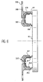
- FIG. 6 shows a radial type seal, according to the invention. It is applied here against the radial surface 11 of a rotating part, such as a plateau or the end surface of a large tree width. It also includes a flexible ribbon 53 in U shape maintained by an inner ring 50 and a outer ring 55. These two rings 50 and 55 have ends 56, 57, 61 and 62 of different lengths two by two for the same reasons as those mentioned for the axial seal. A fixing hole 59 is provided on a branch 58 to fix the joint.
- the essential advantages of the brush seal according to the invention are that it can be radial, as described in Figures 4 and 5, but can be also radial, as described in Figure 6.
Landscapes
- Engineering & Computer Science (AREA)
- General Engineering & Computer Science (AREA)
- Mechanical Engineering (AREA)
- Sealing Devices (AREA)
- Turbine Rotor Nozzle Sealing (AREA)
Abstract
Description
- deux faisceaux d'étanchéité flexibles, parallèles entre eux, et dont l'extrémité de chacun est en contact avec la surface de l'arbre tournant ou fixe ; et
- un corps de maintien dans lequel sont fixés les deux faisceaux d'étanchéité flexible.
- figure 1, déjà décrite, en coupe, un premier type de joint à brosse selon l'art antérieur ;
- figure 2, déjà décrite, en coupe, un deuxième type de joint à brosse selon l'art antérieur ;
- figure 3, en coupe, une première réalisation, radiale, du joint à brosse selon l'invention ;
- figure 4, en coupe, un exemple de montage erroné à éviter, lors la réalisation du joint à brosse selon l'invention ;
- figure 5, une deuxième réalisation, radiale, du joint à brosse selon l'invention ; et
- figure 6, une troisième réalisation, axiale, du joint à brosse selon l'invention.
Claims (4)
- Joint à brosse à double contact, axial ou radial, pour assurer l'étanchéité entre deux enceintes (A, B) soumises à des pressions différentes et situées autour d'un arbre (1), tournant ou fixe, comprenant :caractérisé en ce que les deux faisceaux d'étanchéité flexibles sont constitués par un unique ruban flexible (30, 53) en forme de U et dont la partie centrale est fixée dans le corps de maintien.deux faisceaux d'étanchéité flexibles et parallèles entre eux et dont l'extrémité de chacun (31, 32, 51, 52) est en contact avec la surface extérieure de l'arbre (1) ; etun corps de maintien dans lequel sont fixés les deux faisceaux d'étanchéité flexibles,
- Joint à brosse à double contact selon la revendication 1, caractérisé en ce que le corps de maintien est constitué de deux anneaux, un anneau intérieur (20, 50) et un anneau extérieur (25, 55) tous deux en forme de U et s'imbriquant l'un dans l'autre.
- Joint à brosse à double contact selon la revendication 2, caractérisé en ce que les branches (21, 22, 56, 57) des deux anneaux (20, 25, 50, 55) ne sont pas de même longueur, de sorte que l'extrémité (31, 32, 51, 52) de chaque faisceau d'étanchéité n'est en contact qu'avec un seul anneau.
- Joint à brosse à double contact selon la revendication 2 ou 3, ce joint étant radial, caractérisé en ce qu'il comprend un moyen détrompeur, lors du montage des deux anneaux (20, 25) pour monter ces deux anneaux dans le bon sens.
Applications Claiming Priority (2)
| Application Number | Priority Date | Filing Date | Title |
|---|---|---|---|
| FR9815572 | 1998-12-10 | ||
| FR9815572A FR2787165B1 (fr) | 1998-12-10 | 1998-12-10 | Joint a brosse a double contact |
Publications (2)
| Publication Number | Publication Date |
|---|---|
| EP1008787A1 true EP1008787A1 (fr) | 2000-06-14 |
| EP1008787B1 EP1008787B1 (fr) | 2004-03-24 |
Family
ID=9533799
Family Applications (1)
| Application Number | Title | Priority Date | Filing Date |
|---|---|---|---|
| EP99403084A Expired - Lifetime EP1008787B1 (fr) | 1998-12-10 | 1999-12-09 | Joint à brosse à double contact |
Country Status (6)
| Country | Link |
|---|---|
| US (1) | US6328311B1 (fr) |
| EP (1) | EP1008787B1 (fr) |
| JP (1) | JP2000186772A (fr) |
| CA (1) | CA2291606C (fr) |
| DE (1) | DE69915781T2 (fr) |
| FR (1) | FR2787165B1 (fr) |
Cited By (3)
| Publication number | Priority date | Publication date | Assignee | Title |
|---|---|---|---|---|
| EP1146266A3 (fr) * | 2000-04-13 | 2003-05-07 | MTU Aero Engines GmbH | Joint à brosses |
| WO2010015439A1 (fr) * | 2008-08-05 | 2010-02-11 | Robert Bosch Gmbh | Système d'étanchéité |
| CN102812209A (zh) * | 2010-03-26 | 2012-12-05 | 斯奈克玛 | 涡轮喷气发动机油外壳的密封装置 |
Families Citing this family (12)
| Publication number | Priority date | Publication date | Assignee | Title |
|---|---|---|---|---|
| US20030160392A1 (en) * | 2002-02-12 | 2003-08-28 | Szymbor John A. | Bristle arrangement for brush seal, method and assembly for making same, and method of making brush seal |
| US6996885B2 (en) * | 2002-03-20 | 2006-02-14 | United Technologies Corporation | Method of making bristle arrangement for brush seal |
| US20030201608A1 (en) * | 2002-04-25 | 2003-10-30 | United Technologies Corporation | Brush seal with fewer parts |
| US7270333B2 (en) * | 2002-11-27 | 2007-09-18 | United Technologies Corporation | Brush seal with adjustable clearance |
| US6779799B2 (en) * | 2002-11-27 | 2004-08-24 | General Electric Company | Sealing apparatus for electrical generator ventilation system |
| DE10324709A1 (de) * | 2003-05-30 | 2004-12-16 | Mtu Aero Engines Gmbh | Bürstendichtung zum Abdichten relativ zueinander beweglicher Bauteile gegenüber einem Druckgefälle |
| US6887038B2 (en) * | 2003-09-02 | 2005-05-03 | General Electric Company | Methods and apparatus to facilitate sealing between rotating turbine shafts |
| US7334311B2 (en) * | 2004-11-03 | 2008-02-26 | United Technologies Corporation | Method of forming a nested can brush seal |
| US7226054B2 (en) * | 2004-12-14 | 2007-06-05 | United Technologies Corporation | Clamp lock brush seal assembly |
| US7694564B2 (en) * | 2007-05-21 | 2010-04-13 | Alstom Technology Ltd. | Boiler tube inspection probe with centering mechanism and method of operating the same |
| ES2345310B1 (es) * | 2008-01-31 | 2011-07-22 | Airbus Operations, S.L. | Sellado para uniones rotuladas y su uso. |
| US11619138B2 (en) * | 2021-04-30 | 2023-04-04 | Raytheon Technologies Corporation | Double brush seal assembly |
Citations (2)
| Publication number | Priority date | Publication date | Assignee | Title |
|---|---|---|---|---|
| EP0211275A2 (fr) * | 1985-07-31 | 1987-02-25 | Mtu Motoren- Und Turbinen-Union MàNchen Gmbh | Procédé pour fabriquer des joints-brosses et appareil pour la mise en oeuvre dudit procédé |
| FR2607893A1 (fr) * | 1986-12-06 | 1988-06-10 | Rolls Royce Plc | Joint a brosse |
Family Cites Families (4)
| Publication number | Priority date | Publication date | Assignee | Title |
|---|---|---|---|---|
| US885032A (en) * | 1907-06-24 | 1908-04-21 | Sebastian Ziani De Ferranti | Fluid packing. |
| DE3802653C2 (de) * | 1988-01-29 | 2000-06-29 | Mtu Muenchen Gmbh | Bürstendichtung |
| US5114159A (en) * | 1991-08-05 | 1992-05-19 | United Technologies Corporation | Brush seal and damper |
| DE29600193U1 (de) * | 1996-01-08 | 1996-03-14 | MTU Motoren- und Turbinen-Union München GmbH, 80995 München | Bürstendichtung mit C-förmigem Klemmring |
-
1998
- 1998-12-10 FR FR9815572A patent/FR2787165B1/fr not_active Expired - Fee Related
-
1999
- 1999-11-29 JP JP11337186A patent/JP2000186772A/ja active Pending
- 1999-12-01 CA CA002291606A patent/CA2291606C/fr not_active Expired - Lifetime
- 1999-12-03 US US09/453,511 patent/US6328311B1/en not_active Expired - Lifetime
- 1999-12-09 DE DE69915781T patent/DE69915781T2/de not_active Expired - Lifetime
- 1999-12-09 EP EP99403084A patent/EP1008787B1/fr not_active Expired - Lifetime
Patent Citations (2)
| Publication number | Priority date | Publication date | Assignee | Title |
|---|---|---|---|---|
| EP0211275A2 (fr) * | 1985-07-31 | 1987-02-25 | Mtu Motoren- Und Turbinen-Union MàNchen Gmbh | Procédé pour fabriquer des joints-brosses et appareil pour la mise en oeuvre dudit procédé |
| FR2607893A1 (fr) * | 1986-12-06 | 1988-06-10 | Rolls Royce Plc | Joint a brosse |
Cited By (5)
| Publication number | Priority date | Publication date | Assignee | Title |
|---|---|---|---|---|
| EP1146266A3 (fr) * | 2000-04-13 | 2003-05-07 | MTU Aero Engines GmbH | Joint à brosses |
| US7445212B2 (en) | 2000-04-13 | 2008-11-04 | Mtu Aero Engines Gmbh | Brush seal |
| WO2010015439A1 (fr) * | 2008-08-05 | 2010-02-11 | Robert Bosch Gmbh | Système d'étanchéité |
| CN102812209A (zh) * | 2010-03-26 | 2012-12-05 | 斯奈克玛 | 涡轮喷气发动机油外壳的密封装置 |
| CN102812209B (zh) * | 2010-03-26 | 2015-02-18 | 斯奈克玛 | 涡轮喷气发动机油外壳的密封装置 |
Also Published As
| Publication number | Publication date |
|---|---|
| DE69915781T2 (de) | 2005-02-10 |
| FR2787165B1 (fr) | 2001-01-12 |
| US6328311B1 (en) | 2001-12-11 |
| DE69915781D1 (de) | 2004-04-29 |
| FR2787165A1 (fr) | 2000-06-16 |
| EP1008787B1 (fr) | 2004-03-24 |
| CA2291606C (fr) | 2008-02-05 |
| JP2000186772A (ja) | 2000-07-04 |
| CA2291606A1 (fr) | 2000-06-10 |
Similar Documents
| Publication | Publication Date | Title |
|---|---|---|
| EP1008787B1 (fr) | Joint à brosse à double contact | |
| EP0182716B1 (fr) | Anneau de turbine pour une turbomachine à gaz | |
| EP0003091B1 (fr) | Joint annulaire | |
| EP0572312B1 (fr) | Dispositif d'étanchéité entre des étages d'aubes de redresseur et un tambour tournant | |
| EP3084140B1 (fr) | Bras de guidage d'éléments de forme allongée, en particulier pour une turbomachine | |
| FR2690493A1 (fr) | Joint annulaire à brosse. | |
| EP2893227B1 (fr) | Joint circulaire d'etancheite a brosse | |
| EP0376772A1 (fr) | Raccord tubulaire articulé notamment pour tuyauterie d'échappement de véhicule autombile | |
| EP0723098B1 (fr) | Joint d'étanchéité ultrasouple à double jacquette | |
| FR2994033A1 (fr) | Capot de maintien des cables d'un connecteur | |
| FR2846704A1 (fr) | Joint tisse tubulaire composite pour l'interface horizontale des cloisons d'une turbine a vapeur | |
| FR2560945A1 (fr) | Joints ou paliers flexibles comprenant un element exterieur composite | |
| FR2703105A1 (fr) | Dispositif de purification catalytique des gaz d'échappement d'un moteur, notamment de véhicule automobile. | |
| WO2019043181A1 (fr) | Dispositif d'amortissement des vibrations d'un câble souple ou a isolant mineral integre dans une cavite, câble ainsi equipe et procede de fabrication | |
| EP3943814B1 (fr) | Tronçon de conduit de fumée du type à deux tubes concentriques et son procédé de fabrication | |
| EP2015016A1 (fr) | Echangeur de chaleur pour cuve de chauffage | |
| FR2622671A1 (fr) | Raccord articule entre deux tuyaux | |
| EP3844405B1 (fr) | Dispositif de connexion d'elements tubulaires | |
| FR3092611A1 (fr) | Soufflante de turbomachine | |
| FR2678704A1 (fr) | Dispositif pour le support d'objets allonges. | |
| FR2833665A1 (fr) | Soufflet d'etancheite et joint de transmission correspondant | |
| FR2559834A1 (fr) | Anneau de turbine | |
| EP0479034A1 (fr) | Dispositif de positionnement d'une épissure de fibre optique dans un support | |
| EP1926191A1 (fr) | Boîtier d'appareillage électrique, à face inclinée comportant une entrée de conduit oblongue permettant le pivotement du conduit | |
| FR2759503A1 (fr) | Organe de fermeture de raccord de cable |
Legal Events
| Date | Code | Title | Description |
|---|---|---|---|
| PUAI | Public reference made under article 153(3) epc to a published international application that has entered the european phase |
Free format text: ORIGINAL CODE: 0009012 |
|
| 17P | Request for examination filed |
Effective date: 19991220 |
|
| AK | Designated contracting states |
Kind code of ref document: A1 Designated state(s): DE FR GB |
|
| AX | Request for extension of the european patent |
Free format text: AL;LT;LV;MK;RO;SI |
|
| AKX | Designation fees paid |
Free format text: DE FR GB |
|
| GRAH | Despatch of communication of intention to grant a patent |
Free format text: ORIGINAL CODE: EPIDOS IGRA |
|
| GRAH | Despatch of communication of intention to grant a patent |
Free format text: ORIGINAL CODE: EPIDOS IGRA |
|
| RAP1 | Party data changed (applicant data changed or rights of an application transferred) |
Owner name: SNECMA MOTEURS |
|
| GRAA | (expected) grant |
Free format text: ORIGINAL CODE: 0009210 |
|
| AK | Designated contracting states |
Kind code of ref document: B1 Designated state(s): DE FR GB |
|
| REG | Reference to a national code |
Ref country code: GB Ref legal event code: FG4D Free format text: NOT ENGLISH |
|
| REF | Corresponds to: |
Ref document number: 69915781 Country of ref document: DE Date of ref document: 20040429 Kind code of ref document: P |
|
| GBT | Gb: translation of ep patent filed (gb section 77(6)(a)/1977) |
Effective date: 20040421 |
|
| PLBE | No opposition filed within time limit |
Free format text: ORIGINAL CODE: 0009261 |
|
| STAA | Information on the status of an ep patent application or granted ep patent |
Free format text: STATUS: NO OPPOSITION FILED WITHIN TIME LIMIT |
|
| 26N | No opposition filed |
Effective date: 20041228 |
|
| REG | Reference to a national code |
Ref country code: FR Ref legal event code: CD |
|
| REG | Reference to a national code |
Ref country code: FR Ref legal event code: PLFP Year of fee payment: 17 |
|
| REG | Reference to a national code |
Ref country code: FR Ref legal event code: PLFP Year of fee payment: 18 |
|
| REG | Reference to a national code |
Ref country code: FR Ref legal event code: PLFP Year of fee payment: 19 |
|
| REG | Reference to a national code |
Ref country code: FR Ref legal event code: CD Owner name: SAFRAN AIRCRAFT ENGINES Effective date: 20170719 |
|
| PGFP | Annual fee paid to national office [announced via postgrant information from national office to epo] |
Ref country code: DE Payment date: 20181126 Year of fee payment: 20 |
|
| PGFP | Annual fee paid to national office [announced via postgrant information from national office to epo] |
Ref country code: FR Payment date: 20181127 Year of fee payment: 20 Ref country code: GB Payment date: 20181127 Year of fee payment: 20 |
|
| REG | Reference to a national code |
Ref country code: DE Ref legal event code: R071 Ref document number: 69915781 Country of ref document: DE |
|
| REG | Reference to a national code |
Ref country code: GB Ref legal event code: PE20 Expiry date: 20191208 |
|
| PG25 | Lapsed in a contracting state [announced via postgrant information from national office to epo] |
Ref country code: GB Free format text: LAPSE BECAUSE OF EXPIRATION OF PROTECTION Effective date: 20191208 |