EP1008795A1 - Dispositif d'étanchéité - Google Patents
Dispositif d'étanchéité Download PDFInfo
- Publication number
- EP1008795A1 EP1008795A1 EP99121659A EP99121659A EP1008795A1 EP 1008795 A1 EP1008795 A1 EP 1008795A1 EP 99121659 A EP99121659 A EP 99121659A EP 99121659 A EP99121659 A EP 99121659A EP 1008795 A1 EP1008795 A1 EP 1008795A1
- Authority
- EP
- European Patent Office
- Prior art keywords
- sealing device
- sealing
- socket
- ring
- radially
- Prior art date
- Legal status (The legal status is an assumption and is not a legal conclusion. Google has not performed a legal analysis and makes no representation as to the accuracy of the status listed.)
- Withdrawn
Links
Images


Classifications
-
- F—MECHANICAL ENGINEERING; LIGHTING; HEATING; WEAPONS; BLASTING
- F16—ENGINEERING ELEMENTS AND UNITS; GENERAL MEASURES FOR PRODUCING AND MAINTAINING EFFECTIVE FUNCTIONING OF MACHINES OR INSTALLATIONS; THERMAL INSULATION IN GENERAL
- F16L—PIPES; JOINTS OR FITTINGS FOR PIPES; SUPPORTS FOR PIPES, CABLES OR PROTECTIVE TUBING; MEANS FOR THERMAL INSULATION IN GENERAL
- F16L21/00—Joints with sleeve or socket
- F16L21/02—Joints with sleeve or socket with elastic sealing rings between pipe and sleeve or between pipe and socket, e.g. with rolling or other prefabricated profiled rings
- F16L21/03—Joints with sleeve or socket with elastic sealing rings between pipe and sleeve or between pipe and socket, e.g. with rolling or other prefabricated profiled rings placed in the socket before connection
-
- B—PERFORMING OPERATIONS; TRANSPORTING
- B28—WORKING CEMENT, CLAY, OR STONE
- B28B—SHAPING CLAY OR OTHER CERAMIC COMPOSITIONS; SHAPING SLAG; SHAPING MIXTURES CONTAINING CEMENTITIOUS MATERIAL, e.g. PLASTER
- B28B21/00—Methods or machines specially adapted for the production of tubular articles
- B28B21/56—Methods or machines specially adapted for the production of tubular articles incorporating reinforcements or inserts
- B28B21/563—Gaskets
-
- B—PERFORMING OPERATIONS; TRANSPORTING
- B28—WORKING CEMENT, CLAY, OR STONE
- B28B—SHAPING CLAY OR OTHER CERAMIC COMPOSITIONS; SHAPING SLAG; SHAPING MIXTURES CONTAINING CEMENTITIOUS MATERIAL, e.g. PLASTER
- B28B21/00—Methods or machines specially adapted for the production of tubular articles
- B28B21/76—Moulds
- B28B21/765—Top or bottom rings
Definitions
- the present invention relates to a sealing device for sealing an annular space between two pipe end portions, preferably consisting of concrete, one of the pipe end portions forming a socket having a substantially cylindrical inner surface and the other pipe end portion forming a spigot end introducable into the socket in the axial direction and having a substantially cylindrical outer surface.
- the sealing device according to the invention is of the kind comprising a sealing ring consisting of an elastic material, preferably rubber, and having a sealing portion for sealing the annular space and a mould ring connected with the sealing ring and provided with hollow spaces.
- the sealing device is moulded into the socket at the inner cylindrical surface thereof with the sealing ring positioned adjacent the free end of the socket and the mould ring positioned axially inside the sealing ring.
- the mould ring is at least in connection with the sealing portion of the sealing ring easily compressable so as to be able to take up the deformation of the sealing portion when the spigot end is introduced into the socket and also for taking up an angular position of the spigot end. It is also desirable that the mould ring shall provide a stable mould element when the mould ring is moulded into the socket as the sealing ring will otherwise being provided with an erroneous moulded-in position in the socket.
- Previously known sealing devices present unsatisfactory characteristics with regard to the opposite wishes stated above.
- the object of the invention is to provide a sealing device of the kind stated in which said objects are satisfied in a more reliable way than in previously known sealing devices.
- the sealing device according to the invention is characterized in that at least the hollow spaces positioned adjacent the sealing ring are separated from each other by means of a partition which extends axially and radially obliquely inwards into the socket.
- This design of the partition provides for the required deformation of the mould ring when the spigot end is introduced into the socket while there is at the same time provided for sufficient dimensional stability of the sealing device when the sealing device is moulded into the socket for providing a correct position of the sealing device in the socket.
- all hollow spaces provided in the section of the mould ring which is intended to engage with the cylindrical outer surface of the spigot end are separated from each other by means of partitions which extend axially and radially obliquely inwards into the socket.
- the hollow spaces are in respect of an axial section through the sealing device of elliptic shape with the long axis positioned so that it extends axially and radially obliquely inwards into the socket.
- the sealing device In order to make sure that the sealing device is provided with such a dimensional stability that it maintains its shape when being moulded into the socket it is suitable that the partitions constitute in radial direction a continuous portion extending between the radially outer surface and the radially inner surface of the mould ring.
- the partitions constitute in radial direction a continuous portion extending between the radially outer surface and the radially inner surface of the mould ring.
- the sealing device according to the invention is at its radially outer surface which is moulded into the socket provided with means for preventing or restricting axial displacement of the sealing device and the parts thereof, for example because of the fact that the sealing device is subjected to a radial compression.
- This provides for an increased capacity of the sealing device for maintaining the concentric position between socket and spigot end when the sealing device is subjected to transversely directed forces.
- Said means for preventing or restricting axial displacement of the sealing device and the parts thereof are suitably positioned at the radially outer surface of the sealing device in connection with the transition between the sealing ring and the mould ring and/or at the radially outer surface of the mould ring.
- Said means can be constituted by recesses in the radially outer surface of the sealing device, said recesses being filled by means of the material constituting the socket.
- the recesses have the form of one or several peripherally extending grooves, the grooves having in connection with the transition between the sealing ring and the mould ring a triangular cross-section and are at the radially outer surface of the mould ring constituted by grooves which in pairs define a peripherally extending bead having a dovetail shaped cross-section.
- the radially outer surface of the sealing device is positioned in a cylindrical plane, i.e. without portions extending outside this plane.
- This feature of the sealing device facilitates the manufacturing of the sealing device by the fact that the sealing device can be manufactured in the form of continuous beads which at the vulcanization can rest on said flat surface.
- the sealing device has at its edge portions retainer portions moulded into the material of the socket.
- the mould ring has at its inner edge portion positioned at a distance from the sealing ring a radially inwards extending portion which at least partially constitutes the annular bottom surface of the socket.
- the radially inwards extending portion can be provided with one or several hollow spaces.
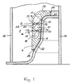
- the sealing device 2 according to the invention shown in axial section in Fig. 1 consists of elastic material, preferably rubber, and is formed in a single part.
- the sealing device 2 comprises a sealing ring 4 having a sealing portion 6 and includes also a mould ring 8.
- the mould ring 8 is provided with annular hollow spaces 10 which in axial section are of elliptic shape with the major axes 12 of the ellipses extending axially and radially obliquely inwards - upwards in the figure. Said orientation of the elliptic hollow spaces 10 provide that the partitions 14 between the hollow spaces extend axially and radially obliquely inwards into the socket into which the sealing device shall be moulded.
- the mould ring is easily compressible so as to take up the deformation of the sealing portion 6 and the angular position of the spigot end when the spigot end is introduced into the socket into which the sealing device has been moulded.
- the mould ring In spite of its capacity of taking up the deformation of the sealing portion and the angular position of the spigot end the mould ring constitutes a stable mould element so that there is provided a correct moulded-in position of the sealing device in the socket.
- the radially continuous portions 16 of the partitions 14 constitute support elements in radial direction which prevent radial compression of the mould ring when the concrete is moulded into the mould while the concrete pipe is moulded and the sealing device is moulded into the socket thereof.
- the sealing device 2 has at its radially outer surface a peripherally extending groove 18.
- the concrete will fill up the groove 18 which provides for a fixation of the sealing device and the parts thereof in the axial direction. This prevents the sealing ring 4 from expanding in the axial direction when the sealing ring 4 is subjected to radially directed forces as a consequence of transverse loads at the joint formed by the socket into which the sealing device is moulded and a spigot end introduced into the socket.
- the mould ring 8 has two peripherally extending grooves 20 forming between themselves a peripherally extending bead 22 having a dovetail-shaped section. The grooves 20 and the bead 22 provide for an axial as well as a radial anchorage of the mould ring 8 in the concrete material of the socket.
- the mould ring 8 has at its inner edge portion positioned at a distance from the sealing ring 4 a radially inwards directed portion 24 which subsequently to the moulding of the sealing device into the socket will partially form the annular bottom surface of the socket.
- the radially inwards directed portion 24 has a retainer bead 26 of dovetail-shaped cross-section.
- the sealing device 2 has a peripherally extending sealing lip 28 and has at its axially inner, peripherally extending edge portion a sealing lip 30.
- the sealing lips 28 and 30 have the object of preventing concrete sludge and the like from entering into the space between the sealing device 2 and the mould surface on which the sealing device is tensioned when it shall be moulded into the pipe socket.
- the concrete pipe comprising a socket into which the sealing device according to the invention is moulded.
- the mould comprises a base ring 32, a pipe-shaped core 34 and an outer mould 36.
- the sealing device 2 according to the invention is tensioned onto the outer surface of the base ring 32, and the sealing lips 28 and 30 of the sealing device 2 engage the outer surface of the base ring for preventing that concrete sludge and the like enters the space between the sealing device 2 and the base ring 32 during the moulding operation.
- the sealing device 2 is moulded into the socket in a well defined position at the inner surface of the socket.
- a spigot end 40 of another concrete pipe which shall be connected with the socket 38 for constituting a pipe joint.
- the spigot end 40 is introduced into the socket 38 the outer surface of the spigot end will engage the sealing portion 6 of the sealing ring 4, the sealing portion 6 being thereby deformed axially inwards and radially outwards in the socket under the influence of the adjacent portion of the mould ring 8.
- the mould ring will be deformed in a correct way in spite of the fact that it has sufficient dimensional stability for providing that the sealing device is moulded into the socket in a correct position.
- the sealing portion 4 of the sealing device 2 is subjected to a radial compression. Because of the fact that the groove 18 is arranged at the transition between the sealing ring 4 and the mould ring, the sealing ring 4 is prevented from expanding in the axial direction. Such an expansion of the sealing ring 4 in the axial direction could lead to a substantially decreased sealing force of the sealing portion 6 of the sealing ring 4. Such an axial expansion could also lead to an eccentric position between the socket and the spigot end at transverse loads which would in turn jeopardize the sealing of the space between the socket 38 and the spigot end 40.
- the mould ring 8 is in an efficient way fixed in the socket 38 by means of the grooves 20, the bead 22 and the retainer portion 26. Also when the mould ring 8 is subjected to an influence from the sealing ring 4 and from the spigot end 40 introduced into the socket 38 the mould ring 8 will retain its correct position in the socket.
- the sealing device 2 according to the invention shown in Fig. 3 consists of a sealing ring 4a having a sealing portion 6a and a mould ring 8a.
- the hollow spaces 42 in the mould ring 8a are in axial section of rhomboid shape which provides that the partitions 44 between the hollow spaces 42 have substantially uniform width.
- the partitions 44 extend in the same way as in the sealing device 2 according to Figs. 1 and 2 obliquely axially and radially inwards into the socket so that the mould ring is provided with a good capacity of taking up the deformation of the sealing ring 4a.
- the means for preventing or restricting axial expansion of the sealing ring 4a consist of several peripherally extending grooves 46 of triangular cross-section.
- the sealing device according to Fig. 3 is designed in the same way as the sealing device 2 according to Figs. 1 and 2 for which reason corresponding parts of the sealing device 2a according to Fig. 3 have the same reference numerals as the sealing device 2 according to Figs. 1 and 2 with the addition a.
- the embodiment of the sealing device 2b according to the invention shown in Fig. 4 comprises a sealing ring 4b having a sealing portion 6b and a mould ring 8b.
- the mould ring 8b has four hollow spaces 48 between which partitions 50, 52 and 54 are provided.
- the partitions 50, 52 and 54 extend obliquely axially and radially inwards into the socket into which the sealing device 2b shall be moulded, the design according to Fig. 4 being such that the partition 50, i.e.
- the partition which is positioned closest to the sealing ring 4b is the most oblique in relation to a radial plane through the sealing ring, while the partition 52 has somewhat less oblique position in relation to the radial plane and the partition 54 has even less oblique position in relation to the radial plane.
- the mould ring 8b is easiest to deform in connection with the sealing ring 4b where the capacity of deformation is of greatest importance, and has a larger resistance against deformation under influence of the concrete when the sealing ring is moulded into the socket at a distance from the sealing ring 4b, i.e. at its central portion.
- the sealing ring 4b has at its free, forward edge a peripherally extending groove 56 defining a retainer portion 58 providing for an efficient anchorage of the forward end of the sealing device in the concrete material.
- the means for preventing axial displacement of the sealing ring 4b are constituted by two peripherally extending grooves 60 having triangular cross-sections, while the retainer portion of the mould ring 8b is constituted by three peripherally extending grooves 62 defining between themselves beads 64 having dovetail-shaped cross-sections.
- the sealing device 2b is designed in substantially the same way as the sealing devices according to Figs. 1, 2 and 3 for which reason corresponding portions are provided with the same reference numerals as in these figures with the addition of b.
- the embodiment of the sealing device 2c according to the invention shown in Fig. 5 differs form the previously described embodiments of the sealing device substantially only in the respect that the inner, radially inwards directed edge portion 24c of the sealing device is provided with a hollow space 64 having elliptic axial section, the main axis of the elliptic hollow space being positioned in the radial plane.
- the embodiment according to Fig. 5 is in all essential respects designed in agreement with the embodiment according to Figs. 1 and 2 with the exception that the device for preventing or restricting axial displacement of the parts of the sealing device at the transition between the sealing ring 4c and the mould ring 2c is designed in accordance with Fig. 3.
- Corresponding parts of the sealing device have the same reference numerals as in the embodiments previously described with the addition of c.
Landscapes
- Engineering & Computer Science (AREA)
- Mechanical Engineering (AREA)
- Manufacturing & Machinery (AREA)
- Chemical & Material Sciences (AREA)
- Ceramic Engineering (AREA)
- General Engineering & Computer Science (AREA)
- Joints With Sleeves (AREA)
- Gasket Seals (AREA)
Applications Claiming Priority (2)
| Application Number | Priority Date | Filing Date | Title |
|---|---|---|---|
| SE9804246A SE9804246L (sv) | 1998-12-07 | 1998-12-07 | Tätningsanordning |
| SE9804246 | 1998-12-07 |
Publications (1)
| Publication Number | Publication Date |
|---|---|
| EP1008795A1 true EP1008795A1 (fr) | 2000-06-14 |
Family
ID=20413587
Family Applications (1)
| Application Number | Title | Priority Date | Filing Date |
|---|---|---|---|
| EP99121659A Withdrawn EP1008795A1 (fr) | 1998-12-07 | 1999-11-02 | Dispositif d'étanchéité |
Country Status (3)
| Country | Link |
|---|---|
| EP (1) | EP1008795A1 (fr) |
| NO (1) | NO995984L (fr) |
| SE (1) | SE9804246L (fr) |
Cited By (4)
| Publication number | Priority date | Publication date | Assignee | Title |
|---|---|---|---|---|
| FR2807695A1 (fr) * | 2000-04-12 | 2001-10-19 | Forsheda | Procede de moulage de l'about femelle a joint annulaire integre d'un element de canalisation en beton |
| EP1167854A1 (fr) * | 2000-06-23 | 2002-01-02 | LWM Werkzeug- und Maschinenbau GmbH | Joint d'étanchéité pour un raccord à manchon |
| EP1600568A1 (fr) * | 2004-05-27 | 2005-11-30 | Theodor Cordes GmbH & Co. KG | Tuyau posé en terre avec protection contre les racines |
| CN1299040C (zh) * | 2004-12-16 | 2007-02-07 | 葛文宇 | 大直径水泥管道的柔性连接装置 |
Citations (7)
| Publication number | Priority date | Publication date | Assignee | Title |
|---|---|---|---|---|
| DE3310264A1 (de) * | 1983-03-22 | 1984-09-27 | Phoenix Ag, 2100 Hamburg | Gummiring zum abdichten eines muffenrohrspaltes |
| DE3345569C2 (fr) | 1983-07-06 | 1988-01-07 | Denso-Chemie Wedekind Kg, 5090 Leverkusen, De | |
| EP0449082A2 (fr) * | 1990-03-24 | 1991-10-02 | Phoenix Aktiengesellschaft | Raccord à manchon |
| DE9416596U1 (de) * | 1994-10-17 | 1995-01-26 | Theodor Cordes GmbH & Co KG, 48308 Senden | Ringelement für Schachtbauwerke |
| DE9420063U1 (de) * | 1994-12-15 | 1995-03-09 | Pebüso-Betonwerke Heribert Büscher GmbH & Co, 48155 Münster | Betonrohr mit kragenartiger Dichtung |
| WO1995016872A1 (fr) * | 1993-12-15 | 1995-06-22 | Forsheda Ab | Dispositif d'etancheite, element de moulage et conduit |
| EP0859183A1 (fr) * | 1997-02-13 | 1998-08-19 | ALBERT STEINHOFF GmbH | Anneau d'étanchéité pour anneaux de puits d'accès |
-
1998
- 1998-12-07 SE SE9804246A patent/SE9804246L/xx not_active Application Discontinuation
-
1999
- 1999-11-02 EP EP99121659A patent/EP1008795A1/fr not_active Withdrawn
- 1999-12-06 NO NO995984A patent/NO995984L/no not_active Application Discontinuation
Patent Citations (7)
| Publication number | Priority date | Publication date | Assignee | Title |
|---|---|---|---|---|
| DE3310264A1 (de) * | 1983-03-22 | 1984-09-27 | Phoenix Ag, 2100 Hamburg | Gummiring zum abdichten eines muffenrohrspaltes |
| DE3345569C2 (fr) | 1983-07-06 | 1988-01-07 | Denso-Chemie Wedekind Kg, 5090 Leverkusen, De | |
| EP0449082A2 (fr) * | 1990-03-24 | 1991-10-02 | Phoenix Aktiengesellschaft | Raccord à manchon |
| WO1995016872A1 (fr) * | 1993-12-15 | 1995-06-22 | Forsheda Ab | Dispositif d'etancheite, element de moulage et conduit |
| DE9416596U1 (de) * | 1994-10-17 | 1995-01-26 | Theodor Cordes GmbH & Co KG, 48308 Senden | Ringelement für Schachtbauwerke |
| DE9420063U1 (de) * | 1994-12-15 | 1995-03-09 | Pebüso-Betonwerke Heribert Büscher GmbH & Co, 48155 Münster | Betonrohr mit kragenartiger Dichtung |
| EP0859183A1 (fr) * | 1997-02-13 | 1998-08-19 | ALBERT STEINHOFF GmbH | Anneau d'étanchéité pour anneaux de puits d'accès |
Non-Patent Citations (1)
| Title |
|---|
| "DENSO-CRET-BL IST EIN DICHTRING AUS ELASTOMEREN MIT DICHTER STRUKTURE FUER DIE DENSO-CRET-BL-STECKMUFFE, EINE ROHRVERBINDUNG FUER BETONROHRE NACH DIN 4032 UND STAHLBETONROHRE NACH DIN 4035, INDER DAS DICHTMITTEL BEI DER HERSTELLUNG DES ROHRES FEST MIT DER MUFFE VERBUNDEN WIRD", PRODUKTINFORMATION DENSO, XX, XX, 1 January 1900 (1900-01-01), XX, pages 01/02, XP002940501 |
Cited By (4)
| Publication number | Priority date | Publication date | Assignee | Title |
|---|---|---|---|---|
| FR2807695A1 (fr) * | 2000-04-12 | 2001-10-19 | Forsheda | Procede de moulage de l'about femelle a joint annulaire integre d'un element de canalisation en beton |
| EP1167854A1 (fr) * | 2000-06-23 | 2002-01-02 | LWM Werkzeug- und Maschinenbau GmbH | Joint d'étanchéité pour un raccord à manchon |
| EP1600568A1 (fr) * | 2004-05-27 | 2005-11-30 | Theodor Cordes GmbH & Co. KG | Tuyau posé en terre avec protection contre les racines |
| CN1299040C (zh) * | 2004-12-16 | 2007-02-07 | 葛文宇 | 大直径水泥管道的柔性连接装置 |
Also Published As
| Publication number | Publication date |
|---|---|
| SE9804246L (sv) | 2000-06-08 |
| NO995984L (no) | 2000-06-08 |
| SE9804246D0 (sv) | 1998-12-07 |
| NO995984D0 (no) | 1999-12-06 |
Similar Documents
| Publication | Publication Date | Title |
|---|---|---|
| CA1241033A (fr) | Joint d'etancheisation au point de rencontre d'une canalisation d'egout et d'un puits de visite, et son mode d'emploi | |
| FI85539B (fi) | Formnings- och taetningsring. | |
| US7658350B2 (en) | Retaining member | |
| US6277315B1 (en) | Method for manufacturing sealing rings | |
| US20020124924A1 (en) | Lightened safety support for tire | |
| CN205036765U (zh) | 环形连杆组件及包括其的系统 | |
| JP5295364B2 (ja) | 移行領域を有する横揺れブーツ | |
| GB2230295A (en) | Ball joint | |
| EP1008795A1 (fr) | Dispositif d'étanchéité | |
| AU675751B2 (en) | A sealing device, a mould element and a pipe | |
| US6997614B2 (en) | Elastic rubber bearing | |
| EP1366318B1 (fr) | Couplage pour le raccordement d'un tube ou d'un flexible par poussee | |
| US7607986B2 (en) | Convoluted boot assembly | |
| US4511277A (en) | Ball joints and liners therefor | |
| US6749184B2 (en) | Air spring and method for making the same | |
| US6076834A (en) | Sealing element | |
| CN114787530A (zh) | 汽车悬架系统的颠簸缓冲器及生产这种颠簸缓冲器的方法 | |
| US5280972A (en) | Pipe joint | |
| US6679662B2 (en) | Expansible plug | |
| JP2023550786A (ja) | パイプ継手挿入デバイス、パイプ継手アセンブリ、及び、それらの形成方法 | |
| US3557421A (en) | Method for making a self-locking ring | |
| US4395074A (en) | Connecting spike for flexibly connecting two chain links of a track | |
| JP3491058B2 (ja) | アキシャルリップ付ベアリングシール | |
| JP4041115B2 (ja) | ジョイントブーツ | |
| EP0896173A2 (fr) | Dispositf d'étanchéité |
Legal Events
| Date | Code | Title | Description |
|---|---|---|---|
| PUAI | Public reference made under article 153(3) epc to a published international application that has entered the european phase |
Free format text: ORIGINAL CODE: 0009012 |
|
| AK | Designated contracting states |
Kind code of ref document: A1 Designated state(s): AT BE CH CY DE DK ES FI FR GB GR IE IT LI LU MC NL PT SE |
|
| AX | Request for extension of the european patent |
Free format text: AL;LT;LV;MK;RO;SI |
|
| 17P | Request for examination filed |
Effective date: 20001110 |
|
| TPAD | Observations filed by third parties |
Free format text: ORIGINAL CODE: EPIDOS TIPA |
|
| AKX | Designation fees paid |
Free format text: AT BE CH CY DE DK ES FI FR GB GR IE IT LI LU MC NL PT SE |
|
| STAA | Information on the status of an ep patent application or granted ep patent |
Free format text: STATUS: THE APPLICATION IS DEEMED TO BE WITHDRAWN |
|
| 18D | Application deemed to be withdrawn |
Effective date: 20020601 |