EP1008868A1 - Couche mince optique, procédé de son production et dispositif optique utilisant cette couche mince - Google Patents
Couche mince optique, procédé de son production et dispositif optique utilisant cette couche mince Download PDFInfo
- Publication number
- EP1008868A1 EP1008868A1 EP99124470A EP99124470A EP1008868A1 EP 1008868 A1 EP1008868 A1 EP 1008868A1 EP 99124470 A EP99124470 A EP 99124470A EP 99124470 A EP99124470 A EP 99124470A EP 1008868 A1 EP1008868 A1 EP 1008868A1
- Authority
- EP
- European Patent Office
- Prior art keywords
- optical
- thin
- film material
- oxide
- film
- Prior art date
- Legal status (The legal status is an assumption and is not a legal conclusion. Google has not performed a legal analysis and makes no representation as to the accuracy of the status listed.)
- Granted
Links
- 239000010409 thin film Substances 0.000 title claims abstract description 133
- 239000000463 material Substances 0.000 title claims abstract description 122
- 230000003287 optical effect Effects 0.000 title claims abstract description 101
- 238000000034 method Methods 0.000 title claims description 10
- 238000004519 manufacturing process Methods 0.000 title description 2
- KZUNJOHGWZRPMI-UHFFFAOYSA-N samarium atom Chemical compound [Sm] KZUNJOHGWZRPMI-UHFFFAOYSA-N 0.000 claims abstract description 24
- 229910052772 Samarium Inorganic materials 0.000 claims abstract description 19
- 150000001875 compounds Chemical class 0.000 claims abstract description 14
- 229910044991 metal oxide Inorganic materials 0.000 claims abstract description 14
- 150000004706 metal oxides Chemical class 0.000 claims abstract description 14
- 239000000126 substance Substances 0.000 claims abstract description 13
- 239000010936 titanium Substances 0.000 claims abstract description 13
- RTAQQCXQSZGOHL-UHFFFAOYSA-N Titanium Chemical compound [Ti] RTAQQCXQSZGOHL-UHFFFAOYSA-N 0.000 claims abstract description 6
- 229910052719 titanium Inorganic materials 0.000 claims abstract description 6
- 239000000758 substrate Substances 0.000 claims description 32
- TWNQGVIAIRXVLR-UHFFFAOYSA-N oxo(oxoalumanyloxy)alumane Chemical compound O=[Al]O[Al]=O TWNQGVIAIRXVLR-UHFFFAOYSA-N 0.000 claims description 30
- FKTOIHSPIPYAPE-UHFFFAOYSA-N samarium(iii) oxide Chemical compound [O-2].[O-2].[O-2].[Sm+3].[Sm+3] FKTOIHSPIPYAPE-UHFFFAOYSA-N 0.000 claims description 28
- GWEVSGVZZGPLCZ-UHFFFAOYSA-N Titan oxide Chemical compound O=[Ti]=O GWEVSGVZZGPLCZ-UHFFFAOYSA-N 0.000 claims description 18
- 229910001954 samarium oxide Inorganic materials 0.000 claims description 18
- 229940075630 samarium oxide Drugs 0.000 claims description 18
- OGIDPMRJRNCKJF-UHFFFAOYSA-N titanium oxide Inorganic materials [Ti]=O OGIDPMRJRNCKJF-UHFFFAOYSA-N 0.000 claims description 11
- 229910052782 aluminium Inorganic materials 0.000 claims description 10
- 238000002156 mixing Methods 0.000 claims description 8
- 230000008018 melting Effects 0.000 claims description 6
- 238000002844 melting Methods 0.000 claims description 6
- XAGFODPZIPBFFR-UHFFFAOYSA-N aluminium Chemical compound [Al] XAGFODPZIPBFFR-UHFFFAOYSA-N 0.000 claims description 5
- 239000011369 resultant mixture Substances 0.000 claims description 4
- 238000000151 deposition Methods 0.000 abstract description 64
- 230000008021 deposition Effects 0.000 abstract description 56
- 238000001771 vacuum deposition Methods 0.000 abstract description 10
- 230000006866 deterioration Effects 0.000 abstract description 5
- 239000010408 film Substances 0.000 description 33
- 239000000843 powder Substances 0.000 description 27
- 239000000203 mixture Substances 0.000 description 15
- 238000010521 absorption reaction Methods 0.000 description 14
- VYPSYNLAJGMNEJ-UHFFFAOYSA-N Silicium dioxide Chemical compound O=[Si]=O VYPSYNLAJGMNEJ-UHFFFAOYSA-N 0.000 description 12
- MRELNEQAGSRDBK-UHFFFAOYSA-N lanthanum(3+);oxygen(2-) Chemical compound [O-2].[O-2].[O-2].[La+3].[La+3] MRELNEQAGSRDBK-UHFFFAOYSA-N 0.000 description 9
- 238000005245 sintering Methods 0.000 description 9
- 239000010453 quartz Substances 0.000 description 8
- LIVNPJMFVYWSIS-UHFFFAOYSA-N silicon monoxide Chemical compound [Si-]#[O+] LIVNPJMFVYWSIS-UHFFFAOYSA-N 0.000 description 8
- 230000000052 comparative effect Effects 0.000 description 7
- 230000008020 evaporation Effects 0.000 description 7
- 238000001704 evaporation Methods 0.000 description 7
- 239000006185 dispersion Substances 0.000 description 6
- 239000000395 magnesium oxide Substances 0.000 description 6
- CPLXHLVBOLITMK-UHFFFAOYSA-N magnesium oxide Inorganic materials [Mg]=O CPLXHLVBOLITMK-UHFFFAOYSA-N 0.000 description 6
- AXZKOIWUVFPNLO-UHFFFAOYSA-N magnesium;oxygen(2-) Chemical compound [O-2].[Mg+2] AXZKOIWUVFPNLO-UHFFFAOYSA-N 0.000 description 6
- RVTZCBVAJQQJTK-UHFFFAOYSA-N oxygen(2-);zirconium(4+) Chemical compound [O-2].[O-2].[Zr+4] RVTZCBVAJQQJTK-UHFFFAOYSA-N 0.000 description 6
- 238000010298 pulverizing process Methods 0.000 description 6
- 229910001928 zirconium oxide Inorganic materials 0.000 description 6
- 239000011248 coating agent Substances 0.000 description 5
- 238000000576 coating method Methods 0.000 description 5
- 230000003595 spectral effect Effects 0.000 description 5
- 230000015572 biosynthetic process Effects 0.000 description 4
- 239000011521 glass Substances 0.000 description 4
- 238000010438 heat treatment Methods 0.000 description 4
- 239000012788 optical film Substances 0.000 description 4
- 239000011347 resin Substances 0.000 description 4
- 229920005989 resin Polymers 0.000 description 4
- 238000004383 yellowing Methods 0.000 description 4
- 238000002441 X-ray diffraction Methods 0.000 description 3
- 238000010894 electron beam technology Methods 0.000 description 3
- 239000008187 granular material Substances 0.000 description 3
- 229910052746 lanthanum Inorganic materials 0.000 description 3
- 238000000465 moulding Methods 0.000 description 3
- 238000004544 sputter deposition Methods 0.000 description 3
- CURLTUGMZLYLDI-UHFFFAOYSA-N Carbon dioxide Chemical compound O=C=O CURLTUGMZLYLDI-UHFFFAOYSA-N 0.000 description 2
- MYMOFIZGZYHOMD-UHFFFAOYSA-N Dioxygen Chemical compound O=O MYMOFIZGZYHOMD-UHFFFAOYSA-N 0.000 description 2
- MCMNRKCIXSYSNV-UHFFFAOYSA-N Zirconium dioxide Chemical compound O=[Zr]=O MCMNRKCIXSYSNV-UHFFFAOYSA-N 0.000 description 2
- 239000000853 adhesive Substances 0.000 description 2
- 230000001070 adhesive effect Effects 0.000 description 2
- 229910052681 coesite Inorganic materials 0.000 description 2
- 229910052906 cristobalite Inorganic materials 0.000 description 2
- FPHIOHCCQGUGKU-UHFFFAOYSA-L difluorolead Chemical compound F[Pb]F FPHIOHCCQGUGKU-UHFFFAOYSA-L 0.000 description 2
- 229910001882 dioxygen Inorganic materials 0.000 description 2
- 238000011156 evaluation Methods 0.000 description 2
- FZLIPJUXYLNCLC-UHFFFAOYSA-N lanthanum atom Chemical compound [La] FZLIPJUXYLNCLC-UHFFFAOYSA-N 0.000 description 2
- 229910052751 metal Inorganic materials 0.000 description 2
- 239000005304 optical glass Substances 0.000 description 2
- 238000005240 physical vapour deposition Methods 0.000 description 2
- 239000000377 silicon dioxide Substances 0.000 description 2
- 238000007711 solidification Methods 0.000 description 2
- 230000008023 solidification Effects 0.000 description 2
- 230000000087 stabilizing effect Effects 0.000 description 2
- 229910052682 stishovite Inorganic materials 0.000 description 2
- 238000002834 transmittance Methods 0.000 description 2
- 229910052905 tridymite Inorganic materials 0.000 description 2
- XLYOFNOQVPJJNP-UHFFFAOYSA-N water Substances O XLYOFNOQVPJJNP-UHFFFAOYSA-N 0.000 description 2
- PNEYBMLMFCGWSK-UHFFFAOYSA-N aluminium oxide Inorganic materials [O-2].[O-2].[O-2].[Al+3].[Al+3] PNEYBMLMFCGWSK-UHFFFAOYSA-N 0.000 description 1
- QVGXLLKOCUKJST-UHFFFAOYSA-N atomic oxygen Chemical compound [O] QVGXLLKOCUKJST-UHFFFAOYSA-N 0.000 description 1
- 230000005540 biological transmission Effects 0.000 description 1
- 239000001569 carbon dioxide Substances 0.000 description 1
- 229910002092 carbon dioxide Inorganic materials 0.000 description 1
- 238000006243 chemical reaction Methods 0.000 description 1
- 238000003912 environmental pollution Methods 0.000 description 1
- 238000009501 film coating Methods 0.000 description 1
- YXEUGTSPQFTXTR-UHFFFAOYSA-K lanthanum(3+);trihydroxide Chemical compound [OH-].[OH-].[OH-].[La+3] YXEUGTSPQFTXTR-UHFFFAOYSA-K 0.000 description 1
- ZLNQQNXFFQJAID-UHFFFAOYSA-L magnesium carbonate Chemical compound [Mg+2].[O-]C([O-])=O ZLNQQNXFFQJAID-UHFFFAOYSA-L 0.000 description 1
- 239000001095 magnesium carbonate Substances 0.000 description 1
- 229910000021 magnesium carbonate Inorganic materials 0.000 description 1
- VTHJTEIRLNZDEV-UHFFFAOYSA-L magnesium dihydroxide Chemical compound [OH-].[OH-].[Mg+2] VTHJTEIRLNZDEV-UHFFFAOYSA-L 0.000 description 1
- 239000000347 magnesium hydroxide Substances 0.000 description 1
- 229910001862 magnesium hydroxide Inorganic materials 0.000 description 1
- 238000001755 magnetron sputter deposition Methods 0.000 description 1
- 229910052760 oxygen Inorganic materials 0.000 description 1
- 239000001301 oxygen Substances 0.000 description 1
- 238000006552 photochemical reaction Methods 0.000 description 1
- 239000002904 solvent Substances 0.000 description 1
Images


Classifications
-
- G—PHYSICS
- G02—OPTICS
- G02B—OPTICAL ELEMENTS, SYSTEMS OR APPARATUS
- G02B1/00—Optical elements characterised by the material of which they are made; Optical coatings for optical elements
- G02B1/10—Optical coatings produced by application to, or surface treatment of, optical elements
- G02B1/11—Anti-reflection coatings
- G02B1/113—Anti-reflection coatings using inorganic layer materials only
- G02B1/115—Multilayers
-
- C—CHEMISTRY; METALLURGY
- C03—GLASS; MINERAL OR SLAG WOOL
- C03C—CHEMICAL COMPOSITION OF GLASSES, GLAZES OR VITREOUS ENAMELS; SURFACE TREATMENT OF GLASS; SURFACE TREATMENT OF FIBRES OR FILAMENTS MADE FROM GLASS, MINERALS OR SLAGS; JOINING GLASS TO GLASS OR OTHER MATERIALS
- C03C17/00—Surface treatment of glass, not in the form of fibres or filaments, by coating
- C03C17/22—Surface treatment of glass, not in the form of fibres or filaments, by coating with other inorganic material
- C03C17/23—Oxides
- C03C17/245—Oxides by deposition from the vapour phase
- C03C17/2456—Coating containing TiO2
-
- C—CHEMISTRY; METALLURGY
- C03—GLASS; MINERAL OR SLAG WOOL
- C03C—CHEMICAL COMPOSITION OF GLASSES, GLAZES OR VITREOUS ENAMELS; SURFACE TREATMENT OF GLASS; SURFACE TREATMENT OF FIBRES OR FILAMENTS MADE FROM GLASS, MINERALS OR SLAGS; JOINING GLASS TO GLASS OR OTHER MATERIALS
- C03C17/00—Surface treatment of glass, not in the form of fibres or filaments, by coating
- C03C17/34—Surface treatment of glass, not in the form of fibres or filaments, by coating with at least two coatings having different compositions
- C03C17/3411—Surface treatment of glass, not in the form of fibres or filaments, by coating with at least two coatings having different compositions with at least two coatings of inorganic materials
- C03C17/3417—Surface treatment of glass, not in the form of fibres or filaments, by coating with at least two coatings having different compositions with at least two coatings of inorganic materials all coatings being oxide coatings
-
- C—CHEMISTRY; METALLURGY
- C23—COATING METALLIC MATERIAL; COATING MATERIAL WITH METALLIC MATERIAL; CHEMICAL SURFACE TREATMENT; DIFFUSION TREATMENT OF METALLIC MATERIAL; COATING BY VACUUM EVAPORATION, BY SPUTTERING, BY ION IMPLANTATION OR BY CHEMICAL VAPOUR DEPOSITION, IN GENERAL; INHIBITING CORROSION OF METALLIC MATERIAL OR INCRUSTATION IN GENERAL
- C23C—COATING METALLIC MATERIAL; COATING MATERIAL WITH METALLIC MATERIAL; SURFACE TREATMENT OF METALLIC MATERIAL BY DIFFUSION INTO THE SURFACE, BY CHEMICAL CONVERSION OR SUBSTITUTION; COATING BY VACUUM EVAPORATION, BY SPUTTERING, BY ION IMPLANTATION OR BY CHEMICAL VAPOUR DEPOSITION, IN GENERAL
- C23C14/00—Coating by vacuum evaporation, by sputtering or by ion implantation of the coating forming material
- C23C14/06—Coating by vacuum evaporation, by sputtering or by ion implantation of the coating forming material characterised by the coating material
- C23C14/08—Oxides
-
- C—CHEMISTRY; METALLURGY
- C03—GLASS; MINERAL OR SLAG WOOL
- C03C—CHEMICAL COMPOSITION OF GLASSES, GLAZES OR VITREOUS ENAMELS; SURFACE TREATMENT OF GLASS; SURFACE TREATMENT OF FIBRES OR FILAMENTS MADE FROM GLASS, MINERALS OR SLAGS; JOINING GLASS TO GLASS OR OTHER MATERIALS
- C03C2217/00—Coatings on glass
- C03C2217/20—Materials for coating a single layer on glass
- C03C2217/21—Oxides
- C03C2217/23—Mixtures
-
- C—CHEMISTRY; METALLURGY
- C03—GLASS; MINERAL OR SLAG WOOL
- C03C—CHEMICAL COMPOSITION OF GLASSES, GLAZES OR VITREOUS ENAMELS; SURFACE TREATMENT OF GLASS; SURFACE TREATMENT OF FIBRES OR FILAMENTS MADE FROM GLASS, MINERALS OR SLAGS; JOINING GLASS TO GLASS OR OTHER MATERIALS
- C03C2218/00—Methods for coating glass
- C03C2218/10—Deposition methods
- C03C2218/15—Deposition methods from the vapour phase
- C03C2218/151—Deposition methods from the vapour phase by vacuum evaporation
Definitions
- This invention relates to an optical-thin-film material used to coat lenses, mirrors and prisms used in optical instruments such as cameras and video cameras or to coat optical devices such as optical disks. It also relates to an optical device provided with an optical thin film formed by coating such a material.
- metal oxide thin-film coating is utilized in their anti-reflection films, filters, mirrors and so forth in order to enhance or reduce the reflection of light or in order to absorb or transmit specific wavelength light.
- multi-layer thin films alternately superposingly formed of thin films having a high refractive index and thin films having a low refractive index can selectively transmit or reflect specific wavelength light.
- they are used as a coating material for optical filters or prisms in a large number in optical instruments as typified by projectors.
- Such multi-layer thin films are produced by physical vapor deposition (PVD) as typified by vacuum deposition (or evaporation) and sputtering.
- the evaporation source targets must be those having shapes suited for individual systems and also can attain stable characteristics during continuous use.
- materials that may cause variations in refractive index because of compositional variations or materials that have much non-homogeniety are not preferable as evaporation substances when the multi-layer thin films are formed by the continuous type systems.
- ultraviolet-curable resins are used in view of an advantage that they can cure in a short time and any solvent need not be used, where widely used is a method in which the ultraviolet-curable resins are irradiated by ultraviolet light to cure to join the thin films.
- ultraviolet-light irradiation causes the metal oxide optical thin films to undergo deoxydation reaction due to photochemical reaction, bringing about a problem of a deterioration of optical thin films, e.g., a decrease in light transmission.
- La 2 Ti 2 O 7-x As materials that may neither cause any compositional variations nor has any non-homogeniety and has a high refractive index, a compound represented by the formula: La 2 Ti 2 O 7-x (wherein x is 0.3 to 0.7) is known in the art as disclosed in Japanese Patent Application Laid-Open No. 6-235803.
- the materials may so greatly scatter that it takes a long premelt time for stabilizing evaporation sources, or their continuous use may cause compositional changes, resulting in a change in refractive index.
- the multi-layer formation of films may result in a difference of values from designed values.
- the irradiation to deposited thin films with ultraviolet light may cause an increase in absorptivity to make it unable to bond the thin films by using the ultraviolet-curable resins.
- this material may so greatly scatter at the time of premelting that it must be premelted for a long time every time materials are added. Moreover, it may cause a deterioration due to irradiation with ultraviolet light. Thus, this material is not a preferred material.
- substances or compounds which have a refractive index intermediate between that of aluminum oxide (Al 2 O 3 ), having a refractive index of about 1.65, and that of zirconium oxide (ZrO 2 ), having a refractive index of about 2.0.
- Such substances or compounds include silicon monoxide (SiO), magnesium oxide (MgO), lead fluoride (PbF 2 ), a mixture of aluminum oxide (Al 2 O 3 ) and zirconium oxide (ZrO 2 ), disclosed in U.S. Patent No. 3,934,961, and a mixture of lanthanum oxide (La 2 O 3 ) and aluminum oxide (Al 2 O 3 ), disclosed in Japanese Patent Application Laid-Open No. 6-184730, which have been put into use.
- the silicon monoxide (SiO) has a problem that thin films cause an absorption to result in a decrease of transmittance.
- the magnesium oxide (MgO) has a problem that it reacts with water or carbon dioxide in the air to change into magnesium hydroxide or magnesium carbonate to cause clouding.
- the lead fluoride (PbF 2 ) has a problem of environmental pollution due to lead.
- the mixture of lanthanum oxide (La 2 O 3 ) and aluminum oxide (Al 2 O 3 ) has a problem that the lanthanum oxide in the mixture reacts with water in the air to change into lanthanum hydroxide to cause expansion, making sinterd evaporation source materials and formed films break down. Their breaking down into powder causes fine particulate matters because of chemicals which may scatter when dissolved, to further cause a problem of compositional deviation in film materials during the deposition.
- deposition materials are conventionally used as substances or mixtures achievable of the refractive index intermediate between alumina (about 1.65) and zirconia (about 2.0), they have properties not undesirable as deposition materials, causative of compositional deviation or occurrence of absorption during the deposition.
- a first object of the present invention is to solve the above problems the prior art has had, and provide a material for optical thin films which has a relatively high refractive index and does not cause any compositional deviation to enable continuous deposition when used as a vacuum deposition material, and does not cause any deterioration due to ultraviolet-light irradiation, and also to provide an optical device having superior optical characteristics, comprising an optical thin film formed by coating such a material.
- a second object of the present invention is to provide a material for optical thin films which has a refractive index of about 1.65 to 1.9, does not cause any compositional deviation to enable continuous deposition when used as a vacuum deposition material, and has good quality, and also to provide an optical device having superior optical characteristics, comprising an optical thin film formed by coating such a material.
- the present invention provides an optical-thin-film material comprising a metal oxide containing samarium and titanium.
- the present invention also provides an optical device comprising:
- the present invention also provides an optical device comprising:
- the present invention provides an optical-thin-film material comprising a compound represented by the following chemical formula: Sm 1-x Al 1+x O 3 wherein -1 ⁇ x ⁇ 1; and also provides an optical device comprising such an optical-thin-film material and corresponding to the above two types of optical devices.
- the present invention still also provides a process for producing the above optical-thin-film materials, the process comprising the steps of:
- optical-thin-film material having a relatively high refractive index will be described first, which is a first embodiment of the present invention.
- This optical-thin-film material comprises a metal oxide containing samarium (Sm) and titanium (Ti) as metallic elements, and preferably a sintered product or fused product composed chiefly of from 10 to 80% by weight of samarium oxide (Sm 2 O 3 ) and the balance of titanium oxide (TiO 2 ).
- This sintered product is obtained by a production process comprising mixing a power of samarium oxide and a powder of titanium oxide in a desired compositional proportion as described above, and pressure-molding the resultant mixture into granules or a platelike target, followed by sintering in vacuum or in the atmosphere at a temperature of 1,400°C or above.
- the pressure-molded product before sintering may be melted at a higher temperature and then solidified to form a fused product.
- Such a sintered product or fused product is melted and evaporated chiefly by means of an electron gun and is formed by deposition as an optical thin film on any intended substrate.
- the sintered product or fused product is melted chiefly by means of an electron gun, but resistance heating, high-frequency heating, or sputtering may also be used.
- the compositional proportion of a mixture of the both may be changed to set its refractive index selectively to any desired value within the range of from 1.9 to 2.4. Also, the optical-thin-film material does not scatter during the melting with an electron gun and also does not cause any compositional variations, and hence continuous film formation can be made.
- the optical thin film having a high refractive index formed using the material according to the first embodiment of the present invention, may superposingly be formed in combination with other optical thin films having various refractive indexes to make up optical multi-layer thin films to obtain various multi-layer thin films having good optical characteristics.
- the substrate on which the optical thin film is formed may include, but not particularly limited to, optical glass such as prisms, filters and so forth, as well as display screens of cathode ray tubes, and lenses of eye-glasses and cameras.
- the optical thin film having a high refractive index, formed using the material according to the first embodiment of the present invention does not cause any increase in absorptivity even upon irradiation by ultraviolet light, and does not cause any problem even when bonded with an ultraviolet-curable resin.
- Fig. 1 schematically illustrates an optical system employing as an anti-reflection film a film formed of the optical-thin-film material of the present invention.
- reference numerals 1 and 2 each denote a lens.
- Anti-reflection films are formed on light incident and emergent surfaces of these lenses 1 and 2.
- Fig. 2 schematically cross-sectionally illustrates an example of layer configuration of an anti-reflection film formed on any of the lenses 1 and 2 of the optical system shown in Fig. 1.
- reference numeral 11 denotes a substrate constituting the lens.
- high-refractive-index layers 12 1 and 12 2 and low-refractive-index layers 13 1 and 13 2 are alternately superposed.
- materials for the high-refractive-index layers 12 1 and 12 2 the metal oxide containing samarium and titanium, which is the first embodiment of the present invention, is used.
- materials for the low-refractive-index layers 13 1 and 13 2 SiO 2 is used.
- the high-refractive-index layers 12 1 and 12 2 each have a refractive index of 2.17 to near ultraviolet light of 365 nm in wavelength
- the low-refractive-index layers 13 1 and 13 2 a refractive index of 1.45.
- optical-thin-film material according to the first embodiment of the present invention will be described below in greater detail by giving Examples for deposition materials.
- the present invention is by no means limited to these Examples.
- Powder of samarium oxide (Sm 2 O 3 ) and powder of titanium oxide (TiO 2 ) were mixed in a weight ratio of 69:31 (molar ratio 1:2), and the mixture obtained was pressure-molded into granules, followed by sintering at 1,580°C for 4 hours in the atmosphere to produce a granular deposition material.
- This granular deposition material was set in a depositing hearth of an electron gun (JEBG102, manufactured by Nippon Denshi K.K.) disposed in a vacuum deposition coater (BMC850, manufactured by Shincron CO., LTD.).
- the inside of the system was evacuated up to 1 ⁇ 10 -5 Torr.
- the synthetic quartz flat plate was taken out.
- Ns is the index of substrate.
- the optical thin film according to the present Example had a refractive index (n) of 2.18 at wavelength 487 nm as shown in Table 1, and showed no absorption in the visible region and up to wavelength of 370 nm.
- the synthetic quartz flat plate provided with the optical thin film of the present Example was also irradiated by ultraviolet rays of 360 nm in wavelength and 200 mW/cm 2 in intensity for 5 seconds by means of an ultraviolet ray irradiator (SUNCURE202-PS, manufactured by AGC), and its absorptivity was measured immediately thereafter to find that the absorptivity was 0.2% or less in the visible region and there was seen no increase.
- SUNCURE202-PS ultraviolet ray irradiator
- a granular deposition material was produced in the same manner as in Example 1 except that the powder of samarium oxide (Sm 2 O 3 ) and powder of titanium oxide (TiO 2 ) were mixed in a weight ratio of 54:46 (molar ratio 1:4).
- the subsequent procedure of Example 1 was repeated to deposit an optical thin film on a synthetic quartz flat plate. Thereafter, the optical thin film was tested similarly to find that the optical thin film had a refractive index (n) of 2.37 as shown in Table 1 and showed no absorption in the visible region and up to wavelength of 370 nm.
- the synthetic quartz flat plate provided with the optical thin film of the present Example was also irradiated by ultraviolet rays in the same manner as in Example 1, and its absorptivity was measured to find that there was seen no increase in absorptivity.
- a granular deposition material was produced in the same manner as in Example 1 except that the powder of samarium oxide (Sm 2 O 3 ) and powder of titanium oxide (TiO 2 ) were mixed in a weight ratio of 81:19 (molar ratio 1:1).
- the subsequent procedure of Example 1 was repeated to deposit an optical thin film on a synthetic quartz flat plate. Thereafter, the optical thin film was tested similarly to find that the optical thin film had a refractive index (n) of 2.03 as shown in Table 1 and showed no absorption in the visible region and up to wavelength of 370 nm.
- the synthetic quartz flat plate provided with the optical thin film of the present Example was also irradiated by ultraviolet rays in the same manner as in Example 1, and its absorptivity was measured to find that there was seen no increase in absorptivity.
- Example 1 The procedure of Example 1 was repeated except that thin films of 125 nm in optical film thickness were continuously deposited ten times without replenishing the granular deposition material.
- the films formed were compositionally analyzed with a fluorescent X-ray analyzer (RIX-3000, manufactured by Rigaku Denki K.K.), and there was seen no compositional change. Their refractive index (n) was also measured, and similarly there was seen no change.
- This granular deposition material was deposited on a synthetic quartz flat plate in the same manner as in Example 1, which was then irradiated by ultraviolet rays, and its absorptivity was measured immediately thereafter to find that, as shown in Table 1, the absorptivity was seen to increase by 2.4% or more.
- the deposition material comprising samarium oxide and titanium oxide according to the present invention caused no scattering of material and also, as shown in Table 2, showed a short melting time.
- this is a material preferable as a material for continuous deposition.
- the deposition material comprising lanthanum oxide and titanium oxide greatly scatterred to take a time to melt.
- optical-thin-film material having an intermediate refractive index of from 1.65 to 1.9 will be described below, which is a second embodiment of the present invention.
- This optical-thin-film material comprises a metal oxide containing samarium (Sm) and aluminum (Al) as metallic elements. It is produced by mixing samarium oxide (Sm 2 O 3 ) and aluminum oxide (Al 2 O 3 ) in a desired compositional proportion and, in a sense that the film composition is stable, preferably in such a proportion that the samarium oxide is 0.3 or more in molar ratio to the aluminum oxide, followed by sintering, or melting and solidification.
- This material is compositionally represented by the chemical formula: Sm 1-x Al 1+x O 3 (wherein -1 ⁇ x ⁇ 1).
- a sintered product of this material is obtained by mixing powder of samarium oxide and powder of aluminum oxide in a desired compositional proportion as described above, and press-molding the resultant mixture, followed by sintering in vacuum or in the atmosphere at a temperature of about 1,500°C. After sintering, the sintered product obtained is pulverized to produce a granular deposition material of 1 to 3 mm in diameter.
- the sintered product or the like of the deposition material is melted and evaporated chiefly by means of an electron gun and is formed by deposition as an optical thin film on any intended substrate.
- the sintered product is melted chiefly by means of an electron gun, but resistance heating or high-frequency heating may also be used.
- the compositional proportion of the samarium oxide and aluminum oxide may be changed to set its refractive index to any desired value, which can selectively be set within the range of from 1.65 to 1.9.
- the compositional proportion in the optical thin film can be stable, and continuous deposition can be carried out while replenishing materials. Also, no remarkable absorption or clouding is seen, and optical thin films free of fine particulate matters which may be caused by scattering of chemicals can be obtained, also making it easy to work and use the products.
- the substrate on which the optical thin film is formed may include, but not particularly limited to, optical glass serving as substrates of prisms, filters and so forth, as well as display screens of cathode ray tubes, and lenses of eye-glasses and cameras.
- the optical thin film having an intermediate refractive index formed using the material according to the second embodiment of the present invention, may superposingly be formed in combination with other optical thin films having various refractive indexes to make up optical multi-layer thin films to obtain various multi-layer thin films having good optical characteristics.
- Fig. 3 schematically illustrates an example in which the optical-thin-film material according to the second embodiment of the present invention is used in the anti-reflection films formed on the lenses 1 and 2 of the optical system shown in Fig. 1.
- reference numeral 21 denotes a substrate constituting the lens.
- high-refractive-index layers 22 1 , 22 2 and 22 3 and low-refractive-index layers 23 1 , 23 2 and 23 3 are alternately superposed.
- materials for the high-refractive-index layers 22 1 , 22 2 and 22 3 Sm 1-x Al 1+x O 3 (wherein -1 ⁇ x ⁇ 1) is used.
- the low-refractive-index layers 23 1 , 23 2 and 23 3 As materials for the low-refractive-index layers 23 1 , 23 2 and 23 3 , SiO 2 is used. Also, the high-refractive-index layers 22 1 , 22 2 and 22 3 each have a refractive index of 1.73 to light of 248 nm in wavelength, and the low-refractive-index layers 23 1 , 23 2 and 23 3 , a refractive index of 1.51.
- optical-thin-film material according to the second embodiment of the present invention will be described below in greater detail by giving Examples.
- the present invention is by no means limited to these Examples.
- Powder of samarium oxide (Sm 2 O 3 ) and powder of aluminum oxide (Al 2 O 3 ) were so mixed that the molar ratio of Sm and Al (Sm/Al) was 1, and the mixture obtained was pressure-molded. Thereafter, the molded product obtained was sintered at 1,500°C for about 4 hours in a vacuum of 1 ⁇ 10 -4 Torr or below, followed by pulverization to produce a granular deposition material of 1 to 3 mm in diameter.
- this granular deposition material was loaded in a depositing hearth of an electron gun disposed in a vacuum deposition coater (BMC850, manufactured by Shincron CO., LTD.).
- the inside of the reactor was evacuated up to a pressure of 1 ⁇ 10 -5 Torr.
- oxygen gas was fed into the reactor at 1 ⁇ 10 -4 Torr and electron beams with an accelerating voltage of 8 kV and an emission current of 400 mA were applied to heat and melt the deposition material.
- the refractive index was calculated from peak values of its spectral characteristics and the samarium concentration (in terms of oxide; % by weight) in the film was measured by fluorescent X-ray analysis to obtain the results shown in Fig. 4.
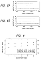
- results are shown in Figs. 5A and 5B.
- the optical thin films formed were put to a weathering test in a thermo-hygrostat (60°C, 95%RH, 100 hours), and whether or not any clouding or yellowing occurred was visually examined.
- Powder of samarium oxide (Sm 2 O 3 ) and powder of aluminum oxide (Al 2 O 3 ) were so mixed that the molar ratio of Sm and Al (Sm/Al) was 0.5, and the mixture obtained was pressure-molded. Thereafter, the molded product obtained was sintered at 1,500°C for about 4 hours in a vacuum of 1 ⁇ 10 -4 Torr or below, followed by pulverization to produce a granular deposition material of 1 to 3 mm in diameter.
- optical thin films were continuously deposited ten times on different substrates in the same manner as in Example 5.
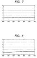
- the refractive index was calculated from peak values of its spectral characteristics and the wavelength dispersion of absorptivity were measured in the same way. Results obtained are shown in Figs. 6 and 7.
- the optical thin films formed were put to a weathering test in a thermo-hygrostat (60°C, 95%RH, 100 hours), and whether or not any clouding or yellowing occurred was visually examined.
- Powder of samarium oxide (Sm 2 O 3 ) and powder of aluminum oxide (Al 2 O 3 ) were so mixed that the molar ratio of Sm and Al (Sm/Al) was 0.33, and the mixture obtained was pressure-molded. Thereafter, the molded product obtained was sintered at 1,500°C for about 4 hours in a vacuum of 1 ⁇ 10 -4 Torr or below, followed by pulverization to produce a granular deposition material of 1 to 3 mm in diameter.
- optical thin films were continuously deposited ten times on different substrates in the same manner as in Example 5.
- the refractive index was calculated from peak values of its spectral characteristics and the wavelength dispersion of absorptivity were measured in the same way. Results obtained are shown in Figs. 6 and 8.
- the optical thin films formed were put to a weathering test in a thermo-hygrostat (60°C, 95%RH, 100 hours), and whether or not any clouding or yellowing occurred was visually examined.
- Powder of samarium oxide (Sm 2 O 3 ) and powder of aluminum oxide (Al 2 O 3 ) were so mixed that the molar ratio of Sm and Al (Sm/Al) was 1, and the mixture obtained was pressure-molded. Thereafter, the molded product obtained was sintered at 1,500°C for about 4 hours in a vacuum of 1 ⁇ 10 -4 Torr or below, followed by pulverization to produce a granular deposition material of 1 to 3 mm in diameter.
- deposition was continuously carried out five times in the same manner as in Example 5. Thereafter, the depositing hearth of the electron gun was replenished with the above deposition material, and the deposition was again continuously carried out five times.
- the refractive index was calculated from peak values of its spectral characteristics and the samarium concentration (in terms of oxide; % by weight) in the film was measured by fluorescent X-ray analysis.
- the refractive index was kept stable and the samarium concentration in the film was also kept stable.
- Powder of lanthanum oxide (La 2 O 3 ) and powder of aluminum oxide (Al 2 O 3 ) were so mixed that the molar ratio of La and Al (La/Al) was 1, and the mixture obtained was pressure-molded. Thereafter, the molded product obtained was sintered at 1,500°C for about 4 hours in a vacuum of 1 ⁇ 10 -4 Torr or below, followed by pulverization to produce a granular deposition material of 1 to 3 mm in diameter.
- this granular deposition material was loaded in a depositing hearth of the electron gun disposed in the vacuum deposition coater.
- the inside of the reactor was evacuated up to a pressure of 1 ⁇ 10 -5 Torr.
- oxygen gas was fed into the reactor at 1 ⁇ 10 -4 Torr and electron beams with an accelerating voltage of 8 kV and an emission current of 400 mA were applied to heat and melt the deposition material.
- the refractive index was calculated from peak values of its spectral characteristics and the lanthanum concentration (in terms of oxide; % by weight) in the film was measured by fluorescent X-ray analysis to obtain the results shown in Fig. 4.
- Powder of magnesium oxide (MgO) was pressure-molded. Thereafter, the molded product obtained was sintered at 1,500°C for about 4 hours in the atmosphere, followed by pulverization to produce a granular deposition material of 1 to 3 mm in diameter. Then, using this deposition material, optical thin films were deposited in the same manner as in Example 5. Thereafter, the optical thin films formed were put to a weathering test in a thermo-hygrostat (60°C, 95%RH, 100 hours), and whether or not any clouding or yellowing occurred was visually examined.
- a thermo-hygrostat 60°C, 95%RH, 100 hours
- An optical-thin-film material comprising a metal oxide containing samarium and titanium, or comprising a compound represented by the following chemical formula: Sm 1-x Al 1+x O 3 wherein -1 ⁇ x ⁇ 1 is disclosed.
- An optical device having an optical thin film formed of such a material is also disclosed.
- This optical-thin-film material does not cause any compositional deviation to enable continuous deposition when used as a vacuum deposition material, and does not cause any deterioration due to ultraviolet-light irradiation.
Landscapes
- Chemical & Material Sciences (AREA)
- Engineering & Computer Science (AREA)
- Chemical Kinetics & Catalysis (AREA)
- Materials Engineering (AREA)
- Organic Chemistry (AREA)
- Physics & Mathematics (AREA)
- General Chemical & Material Sciences (AREA)
- Geochemistry & Mineralogy (AREA)
- Life Sciences & Earth Sciences (AREA)
- Inorganic Chemistry (AREA)
- General Physics & Mathematics (AREA)
- Optics & Photonics (AREA)
- Mechanical Engineering (AREA)
- Metallurgy (AREA)
- Surface Treatment Of Optical Elements (AREA)
- Physical Vapour Deposition (AREA)
Applications Claiming Priority (4)
| Application Number | Priority Date | Filing Date | Title |
|---|---|---|---|
| JP36849898A JP3472169B2 (ja) | 1998-12-09 | 1998-12-09 | 中間屈折率の光学薄膜用蒸着材料および該蒸着材料を用いた光学薄膜 |
| JP36849898 | 1998-12-09 | ||
| JP37572998 | 1998-12-17 | ||
| JP10375729A JP2000180604A (ja) | 1998-12-17 | 1998-12-17 | 高屈折率の光学薄膜材料および該材料を用いた光学薄膜 |
Publications (2)
| Publication Number | Publication Date |
|---|---|
| EP1008868A1 true EP1008868A1 (fr) | 2000-06-14 |
| EP1008868B1 EP1008868B1 (fr) | 2005-03-02 |
Family
ID=26582009
Family Applications (1)
| Application Number | Title | Priority Date | Filing Date |
|---|---|---|---|
| EP99124470A Expired - Lifetime EP1008868B1 (fr) | 1998-12-09 | 1999-12-08 | Couche mince optique, procédé pour sa production et dispositif optique utilisant cette couche mince |
Country Status (3)
| Country | Link |
|---|---|
| US (1) | US6327087B1 (fr) |
| EP (1) | EP1008868B1 (fr) |
| DE (1) | DE69923924T2 (fr) |
Cited By (2)
| Publication number | Priority date | Publication date | Assignee | Title |
|---|---|---|---|---|
| EP1219724A1 (fr) * | 2000-12-29 | 2002-07-03 | MERCK PATENT GmbH | Matériau pour la deposition par vapeur des couches optiques à haute index de refraction |
| WO2003040807A3 (fr) * | 2001-11-02 | 2004-04-15 | Johnson & Johnson Vision Care | Procede de fabrication de lentilles multifocales |
Families Citing this family (21)
| Publication number | Priority date | Publication date | Assignee | Title |
|---|---|---|---|---|
| WO2002001622A2 (fr) * | 2000-06-26 | 2002-01-03 | North Carolina State University | Nouveaux oxydes non cristallins utilises dans des applications optiques, micro-electroniques, et autres |
| US20050040478A1 (en) * | 2001-06-25 | 2005-02-24 | Gerald Lucovsky | Novel non-crystalline oxides for use in microelectronic, optical, and other applications |
| JP3862623B2 (ja) * | 2002-07-05 | 2006-12-27 | キヤノン株式会社 | 光偏向器及びその製造方法 |
| DE10307096A1 (de) * | 2003-02-19 | 2004-09-02 | Merck Patent Gmbh | Aufdampfmaterial zur Herstellung mittelbrechender optischer Schichten |
| JP2005173411A (ja) * | 2003-12-12 | 2005-06-30 | Canon Inc | 光偏向器 |
| JP4574396B2 (ja) * | 2005-03-02 | 2010-11-04 | キヤノン株式会社 | 光偏向器 |
| ES2299335B2 (es) * | 2006-03-09 | 2010-10-13 | Universidad De Cadiz | Metodo para la fabricacion de estructuras opticas con funcionalidad puramente refractivas. |
| JP5170983B2 (ja) * | 2006-05-30 | 2013-03-27 | キヤノン株式会社 | 光偏向器、及びそれを用いた光学機器 |
| JP4881073B2 (ja) * | 2006-05-30 | 2012-02-22 | キヤノン株式会社 | 光偏向器、及びそれを用いた光学機器 |
| US7593934B2 (en) * | 2006-07-28 | 2009-09-22 | Microsoft Corporation | Learning a document ranking using a loss function with a rank pair or a query parameter |
| JP2008191537A (ja) * | 2007-02-07 | 2008-08-21 | Canon Inc | 振動素子、及び振動素子を備える光偏向器 |
| JP5358430B2 (ja) * | 2007-03-30 | 2013-12-04 | 富士チタン工業株式会社 | 蒸着材料及びそれより得られる光学薄膜 |
| JP2009025617A (ja) * | 2007-07-20 | 2009-02-05 | Canon Inc | 揺動体装置、光偏向器およびそれを用いた光学機器 |
| JP2009122383A (ja) * | 2007-11-14 | 2009-06-04 | Canon Inc | 揺動体装置の製造方法、該製造方法により製造された揺動体装置によって構成される光偏向器及び光学機器 |
| JP2009128463A (ja) | 2007-11-21 | 2009-06-11 | Canon Inc | 揺動体装置の製造方法、該製造方法により製造された揺動体装置によって構成される光偏向器及び光学機器 |
| JP2009163198A (ja) * | 2007-12-10 | 2009-07-23 | Canon Inc | 揺動体装置の製造方法、光偏向器、画像形成装置 |
| JP5335654B2 (ja) | 2009-12-04 | 2013-11-06 | キヤノン株式会社 | モード変換素子 |
| US7967435B1 (en) | 2010-04-21 | 2011-06-28 | 3M Innovative Properties Company | Metal detectable lens |
| US8342679B2 (en) | 2010-04-21 | 2013-01-01 | 3M Innovative Properties Company | Metal detectable lens carrier |
| JP2013102060A (ja) | 2011-11-09 | 2013-05-23 | Canon Inc | 荷電粒子光学系、及びそれを用いた描画装置 |
| CN114133226B (zh) * | 2021-12-30 | 2022-11-08 | 苏州晶生新材料有限公司 | 一种光学镀层基材及使用方法 |
Citations (5)
| Publication number | Priority date | Publication date | Assignee | Title |
|---|---|---|---|---|
| US4173778A (en) * | 1976-07-28 | 1979-11-06 | Optical Coating Laboratory, Inc. | Lighting fixtures and glass enclosure having high angle anti-reflection coating |
| US4927239A (en) * | 1983-09-12 | 1990-05-22 | Optische Werke G. Rodenstock | Anti-reflection film for an optical element consisting of an organic material |
| US5340607A (en) * | 1992-03-19 | 1994-08-23 | Merck Patent Gesellschaft Mit Beschrankter Haftung | Vapor-deposition material for the production of high-refraction optical coatings |
| US5415946A (en) * | 1992-06-17 | 1995-05-16 | Merck Patent Gesellschaft Mit Beschrankter Haftung | Vapor-deposition material for the production of optical coatings of medium refractive index |
| US5989626A (en) * | 1995-05-09 | 1999-11-23 | Flex Products, Inc. | Mixed oxide high index optical coating material and method |
Family Cites Families (2)
| Publication number | Priority date | Publication date | Assignee | Title |
|---|---|---|---|---|
| US3934961A (en) | 1970-10-29 | 1976-01-27 | Canon Kabushiki Kaisha | Three layer anti-reflection film |
| US5850309A (en) * | 1996-03-27 | 1998-12-15 | Nikon Corporation | Mirror for high-intensity ultraviolet light beam |
-
1999
- 1999-12-07 US US09/456,949 patent/US6327087B1/en not_active Expired - Lifetime
- 1999-12-08 DE DE69923924T patent/DE69923924T2/de not_active Expired - Lifetime
- 1999-12-08 EP EP99124470A patent/EP1008868B1/fr not_active Expired - Lifetime
Patent Citations (5)
| Publication number | Priority date | Publication date | Assignee | Title |
|---|---|---|---|---|
| US4173778A (en) * | 1976-07-28 | 1979-11-06 | Optical Coating Laboratory, Inc. | Lighting fixtures and glass enclosure having high angle anti-reflection coating |
| US4927239A (en) * | 1983-09-12 | 1990-05-22 | Optische Werke G. Rodenstock | Anti-reflection film for an optical element consisting of an organic material |
| US5340607A (en) * | 1992-03-19 | 1994-08-23 | Merck Patent Gesellschaft Mit Beschrankter Haftung | Vapor-deposition material for the production of high-refraction optical coatings |
| US5415946A (en) * | 1992-06-17 | 1995-05-16 | Merck Patent Gesellschaft Mit Beschrankter Haftung | Vapor-deposition material for the production of optical coatings of medium refractive index |
| US5989626A (en) * | 1995-05-09 | 1999-11-23 | Flex Products, Inc. | Mixed oxide high index optical coating material and method |
Cited By (4)
| Publication number | Priority date | Publication date | Assignee | Title |
|---|---|---|---|---|
| EP1219724A1 (fr) * | 2000-12-29 | 2002-07-03 | MERCK PATENT GmbH | Matériau pour la deposition par vapeur des couches optiques à haute index de refraction |
| US6756137B2 (en) | 2000-12-29 | 2004-06-29 | Merck Patent Gmbh | Vapor-deposition material for the production of high-refractive-index optical layers, and process for the production of the vapor-deposition material |
| WO2003040807A3 (fr) * | 2001-11-02 | 2004-04-15 | Johnson & Johnson Vision Care | Procede de fabrication de lentilles multifocales |
| US7014317B2 (en) | 2001-11-02 | 2006-03-21 | Essilor International (Compagnie Generale D'optique) | Method for manufacturing multifocal lenses |
Also Published As
| Publication number | Publication date |
|---|---|
| US6327087B1 (en) | 2001-12-04 |
| EP1008868B1 (fr) | 2005-03-02 |
| DE69923924T2 (de) | 2006-03-02 |
| DE69923924D1 (de) | 2005-04-07 |
Similar Documents
| Publication | Publication Date | Title |
|---|---|---|
| EP1008868B1 (fr) | Couche mince optique, procédé pour sa production et dispositif optique utilisant cette couche mince | |
| US8263172B2 (en) | Method for producing optical element having multi-layered film | |
| USRE41747E1 (en) | Metal film and metal film-coated member, metal oxide film and metal oxide film-coated member, thin film forming apparatus and thin film forming method for producing metal film and metal oxide film | |
| US6358440B1 (en) | Process for producing thin film, thin film and optical instrument including the same | |
| EP1211524B1 (fr) | Méthode de fabrication d'une composition pour dépôt sous vide, composition pour dépôt sous vide et méthode de fabrication d'un élément optique avec revêtement anti-réfléchissant | |
| US20040071889A1 (en) | Method of producing an antireflection-coated substrate | |
| US7106515B2 (en) | Composition for vapor deposition, method for forming an antireflection film, and optical element | |
| KR101143804B1 (ko) | 중간 굴절률의 광학 층을 제조하기 위한 증착 물질 | |
| JP3723580B2 (ja) | 中程度の屈折率の光学コーテイング製造用の蒸気析出素材 | |
| US4707820A (en) | Optical film and process for producing same | |
| KR101050612B1 (ko) | 고 굴절률의 광학 층을 제조하기 위한 증착 물질 | |
| JP3355786B2 (ja) | 赤外線用光学部品の製造方法 | |
| Kozlowski et al. | Optical coatings for high power lasers | |
| JP3039721B2 (ja) | 蒸着材料及び該蒸着材料を用いた光学薄膜の製造方法 | |
| KR101114652B1 (ko) | 고 굴절률의 광학 층을 제조하기 위한 증착 물질 | |
| JP3404346B2 (ja) | 光学薄膜の製造方法及び光学薄膜を有する基板の製造方法 | |
| JP3353931B2 (ja) | 光学薄膜とこの光学薄膜を形成した光学部品及び反射防止膜とこの反射防止膜を形成したプラスチック製光学部品 | |
| JP3472169B2 (ja) | 中間屈折率の光学薄膜用蒸着材料および該蒸着材料を用いた光学薄膜 | |
| US5262196A (en) | Methods of producing improved optical coatings | |
| Pulker | Coatings on glass substrates | |
| JP2000180604A (ja) | 高屈折率の光学薄膜材料および該材料を用いた光学薄膜 | |
| WO2023042438A1 (fr) | Film de blocage de lumière, film antireflet multicouche, procédé de production dudit film de blocage de lumière, procédé de production dudit film antireflet multicouche, et élément optique | |
| Dubs et al. | Production of stable interference filters by low voltage reactive ion plating |
Legal Events
| Date | Code | Title | Description |
|---|---|---|---|
| PUAI | Public reference made under article 153(3) epc to a published international application that has entered the european phase |
Free format text: ORIGINAL CODE: 0009012 |
|
| AK | Designated contracting states |
Kind code of ref document: A1 Designated state(s): CH DE FR GB IT LI |
|
| AX | Request for extension of the european patent |
Free format text: AL;LT;LV;MK;RO;SI |
|
| 17P | Request for examination filed |
Effective date: 20001026 |
|
| AKX | Designation fees paid |
Free format text: CH DE FR GB IT LI |
|
| 17Q | First examination report despatched |
Effective date: 20031217 |
|
| GRAP | Despatch of communication of intention to grant a patent |
Free format text: ORIGINAL CODE: EPIDOSNIGR1 |
|
| GRAS | Grant fee paid |
Free format text: ORIGINAL CODE: EPIDOSNIGR3 |
|
| GRAA | (expected) grant |
Free format text: ORIGINAL CODE: 0009210 |
|
| AK | Designated contracting states |
Kind code of ref document: B1 Designated state(s): CH DE FR GB IT LI |
|
| PG25 | Lapsed in a contracting state [announced via postgrant information from national office to epo] |
Ref country code: FR Free format text: LAPSE BECAUSE OF NON-PAYMENT OF DUE FEES Effective date: 20050302 |
|
| REG | Reference to a national code |
Ref country code: GB Ref legal event code: FG4D |
|
| REG | Reference to a national code |
Ref country code: CH Ref legal event code: EP |
|
| REG | Reference to a national code |
Ref country code: CH Ref legal event code: NV Representative=s name: BOVARD AG PATENTANWAELTE |
|
| REF | Corresponds to: |
Ref document number: 69923924 Country of ref document: DE Date of ref document: 20050407 Kind code of ref document: P |
|
| PG25 | Lapsed in a contracting state [announced via postgrant information from national office to epo] |
Ref country code: GB Free format text: LAPSE BECAUSE OF NON-PAYMENT OF DUE FEES Effective date: 20051208 |
|
| PLBE | No opposition filed within time limit |
Free format text: ORIGINAL CODE: 0009261 |
|
| STAA | Information on the status of an ep patent application or granted ep patent |
Free format text: STATUS: NO OPPOSITION FILED WITHIN TIME LIMIT |
|
| 26N | No opposition filed |
Effective date: 20051205 |
|
| EN | Fr: translation not filed | ||
| GBPC | Gb: european patent ceased through non-payment of renewal fee |
Effective date: 20051208 |
|
| REG | Reference to a national code |
Ref country code: CH Ref legal event code: PFA Owner name: CANON KABUSHIKI KAISHA Free format text: CANON KABUSHIKI KAISHA#30-2, 3-CHOME, SHIMOMARUKO, OHTA-KU#TOKYO (JP) -TRANSFER TO- CANON KABUSHIKI KAISHA#30-2, 3-CHOME, SHIMOMARUKO, OHTA-KU#TOKYO (JP) |
|
| PGFP | Annual fee paid to national office [announced via postgrant information from national office to epo] |
Ref country code: CH Payment date: 20131216 Year of fee payment: 15 |
|
| REG | Reference to a national code |
Ref country code: CH Ref legal event code: PL |
|
| PG25 | Lapsed in a contracting state [announced via postgrant information from national office to epo] |
Ref country code: CH Free format text: LAPSE BECAUSE OF NON-PAYMENT OF DUE FEES Effective date: 20141231 Ref country code: LI Free format text: LAPSE BECAUSE OF NON-PAYMENT OF DUE FEES Effective date: 20141231 |
|
| PGFP | Annual fee paid to national office [announced via postgrant information from national office to epo] |
Ref country code: IT Payment date: 20151204 Year of fee payment: 17 Ref country code: DE Payment date: 20151231 Year of fee payment: 17 |
|
| REG | Reference to a national code |
Ref country code: DE Ref legal event code: R119 Ref document number: 69923924 Country of ref document: DE |
|
| PG25 | Lapsed in a contracting state [announced via postgrant information from national office to epo] |
Ref country code: IT Free format text: LAPSE BECAUSE OF NON-PAYMENT OF DUE FEES Effective date: 20161208 |
|
| PG25 | Lapsed in a contracting state [announced via postgrant information from national office to epo] |
Ref country code: DE Free format text: LAPSE BECAUSE OF NON-PAYMENT OF DUE FEES Effective date: 20170701 |