EP1008921B1 - Einrichtung zur Anzeige des Anstellwinkels in einem Flugzeug - Google Patents
Einrichtung zur Anzeige des Anstellwinkels in einem Flugzeug Download PDFInfo
- Publication number
- EP1008921B1 EP1008921B1 EP99203493A EP99203493A EP1008921B1 EP 1008921 B1 EP1008921 B1 EP 1008921B1 EP 99203493 A EP99203493 A EP 99203493A EP 99203493 A EP99203493 A EP 99203493A EP 1008921 B1 EP1008921 B1 EP 1008921B1
- Authority
- EP
- European Patent Office
- Prior art keywords
- attack
- angle
- aircraft
- bug
- gauge
- Prior art date
- Legal status (The legal status is an assumption and is not a legal conclusion. Google has not performed a legal analysis and makes no representation as to the accuracy of the status listed.)
- Revoked
Links
- 238000013459 approach Methods 0.000 claims description 17
- 238000000034 method Methods 0.000 claims description 14
- 238000010586 diagram Methods 0.000 description 4
- 235000021170 buffet Nutrition 0.000 description 3
- 238000005259 measurement Methods 0.000 description 3
- 230000008901 benefit Effects 0.000 description 2
- 230000003068 static effect Effects 0.000 description 2
- 241000238876 Acari Species 0.000 description 1
- 230000002159 abnormal effect Effects 0.000 description 1
- 230000001419 dependent effect Effects 0.000 description 1
- 238000001514 detection method Methods 0.000 description 1
Images


Classifications
-
- G—PHYSICS
- G01—MEASURING; TESTING
- G01C—MEASURING DISTANCES, LEVELS OR BEARINGS; SURVEYING; NAVIGATION; GYROSCOPIC INSTRUMENTS; PHOTOGRAMMETRY OR VIDEOGRAMMETRY
- G01C23/00—Combined instruments indicating more than one navigational value, e.g. for aircraft; Combined measuring devices for measuring two or more variables of movement, e.g. distance, speed or acceleration
Definitions
- the present invention relates to the aircraft indicator art.
- the invention relates to an aircraft non-normalized angle-of-attack indicating system as defined in the preamble of claim 1 and to a method for displaying aircraft non-normalized angle-of-attack as defined in the preamble of claim 8.
- Such system and method are known from US-A-3,686,936.
- Angle-of-attack refers to the angle between an aircraft's wing and the oncoming air. For maneuvering flight, or for flight without reference to air speed, angle-of-attack is an extremely useful measure of the aerodynamic state of an aircraft's wing.
- Figure 1a depicts angles of attack for a typical commercial transport corresponding to the following state of the wing, states which are of particular interest to the pilot:
- Figure 1b depicts the relationship between two of the aforementioned angles of attack and Mach number. Notice that there is a significant variation in these angles over the range of Mach numbers experienced by a typical commercial transport aircraft.
- angle-of-attack information has been displayed using a so-called normalized display, in which two key angles of attack (for example, stick-shaker and zero lift) are used as anchor points on the scale.
- stick-shaker angle-of-attack ⁇ ss
- ⁇ z1 zero-lift angle-of-attack
- this is accomplished by a system having the characterizing features of claim 1 and by a method including the characterizing steps of claim 8.
- Knowledge of angle-of-attack is useful in flight, for detection of abnormal flight conditions (including air data measurement failures), and to provide an aircraft's flight crew with general situational awareness about the state of the aircraft's wing.
- the proposed non-normalized angle-of-attack indicating system circumvents this problem by fixing the scale on which angle-of-attack is displayed, and instead moving the bugs for the key values of angle-of-attack as their influencing parameters change.
- This scheme makes the proposed indicator much more reliable in cases where the estimated values of the influencing parameters may be in error, without appreciably compromising each utility in normal operations.
- the proposed non-normalized angle-of-attack indicating system consists of an angle-of-attack indicator in which the pointer, or needle movement is not scaled between salient values such as zero-lift or approach angle-of-attack and stick shaker angle-of-attack.
- angle-of-attack is presented against a fixed scale, or gauge marking degrees of angle-of-attack (or alternatively marked in some other unit of angle-of-attack) while the "bugs" for the salient values (e.g., stick shaker, approach reference and so forth) are shifted as the various influencing factors, which include Mach number, flap position and so forth, vary.
- FIGS 3a and 3b depict two implementations of the inventive angle-of-attack indicator.
- a fixed gauge or scale 30 which is arcuate in shape extending from an indicated -5° angle-of-attack at 6 o'clock, around to a +20° angle-of-attack at 10:30 o'clock. At equal arc spacings, are ticks which indicate angles of attack, within the stated range, in 5° increments.
- a moving needle or pointer 32 arcuately moves on one side of the gauge 30 in a manner to indicate the aircraft's measured angle-of-attack. Actuation of the pointer is more clearly understood with reference to Figs. 5 and 6.
- the bugs 34, 36 are moveably positionable with respect to the gauge 30.
- the first bug 34 is moveable to indicate a first limit condition, such as stick shaker.
- the second bug 36 is moveable with respect to the gauge 30 to indicate a reference condition, such as the reference angle-of-attack to be flown during an approach. Note that the second bug 36 is shown as indicating a range of angle-of-attack values, because there is more than one acceptable value of angle-of-attack for the approach condition.
- FIG. 3a Also depicted in the display system of Fig. 3a is a digital readout of aircraft actual angle-of-attack at 38.
- Figure 3b illustrates an alternate implementation of the inventive non-normalized, aircraft angle-of-attack indicator.
- a gauge 40 comprised of a linear scale extending from a low value of -5° angle-of-attack to a high value of 20° angle-of-attack. Equidistantly spaced along the gauge 40 are tick marks at every five degrees of aircraft angle-of-attack.
- a needle or pointer 42 Positioned on one side of the gauge 40 is a needle or pointer 42 which, in a manner better understood with respect to Figs. 5 and 6, is moveable along the gauge to indicate the aircraft's actual angle-of-attack.
- first and second moveable bugs 44, 46 Positioned with respect to the gauge 40 on the side opposite of the pointer 42 are first and second moveable bugs 44, 46, respectively.
- First moveable bug 44 may be positioned to indicate an upper limit angle-of-attack value, such as stick shaker, whereas the second moveable bug 46 is positionable to indicate a reference value of aircraft angle-of-attack. Note that the second bug 46 is shown as indicating a range of angle-of-attack values, because again there is more than one acceptable value of angle-of-attack for the approach condition.
- the angle-of-attack indicating system of Fig. 3b also includes a digital readout 48 of the aircraft's actual angle-of-attack.
- the primary advantage of the present apparatus and method for displaying aircraft angle-of-attack is that it is far less sensitive to errors in air data or aircraft configuration sensing than prior art displays.
- Figures 4a and 4b depict the inventive non-normalized display indicating 4.5° angle-of-attack at two different Mach numbers.
- the stick shaker bug 50 is shown at its low-Mach position of 11° angle-of-attack.
- Fig. 3a the indicating system depicted in Fig. 3a has been evaluated against a prototypical normalized display known to the prior art.
- the inventive non-normalized display was found to be superior to the normalized display for providing pilots with general situational awareness, and particularly for flying approaches without air speed or other air data information.
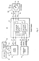
- Fig. 5 is a schematic, block diagram illustrating the preferred embodiment of the present non-normalized aircraft angle-of-attack indicating system, here indicated generally at 60.
- An angle-of-attack (AOA) vane 62 sends raw angle-of-attack data, ⁇ ', over a line 64, to an air data computer 66.
- AOA angle-of-attack
- a pitot-static system 68 monitors and sends both a static pressure signal, P t , over a line 70 to the air data computer and a total pressure signal, P t , over a line 72, to the air data computer 66.
- the air data computer 66 in the normal manner, sends an aircraft's actual angle-of-attack signal ⁇ over a line 74 to a display computer 76.
- the air data computer 66 In addition, in the normal manner the air data computer 66 generates an aircraft Mach value, M, which is transmitted over a line 78 to the display computer 76.
- a series of configuration sensors, indicated generally at 80, on the aircraft communicate several relevant configuration variables to the display computer 76 such as, for example, aircraft landing gear position, over line 82, aircraft flap position, over line 84 and aircraft speed brake position, over line 86.
- the display computer 76 uses the received Mach number, gear position value, flap position value and speed brake position value to look up in a lookup table (in the preferred embodiment), or calculate in an alternate embodiment, the appropriate limit value for angle-of-attack, ⁇ .
- a lookup table in the preferred embodiment
- the display computer out of its sub-block 90 looks up, (or calculates) an appropriate angle-of-attack stick shaker signal level ⁇ ss .
- the display computer inputs aircraft gear position, flap position and speed brake position to generate a second angle-of-attack reference bug, ⁇ ref , which may correspond to, for example, the aircraft zero-lift angle-of-attack.
- the signals ⁇ , over line 94, ⁇ ss , over line 96 and ⁇ ref over line 98 are all fed to the angle-of-attack indicator, 100.
- the angle-of-attack indicator in the normal manner, includes drivers to receive the various signals and deflect a pointer 102 with respect to a scaled gauge 104.
- a moveable first bug 106 indicates the angle-of-attack stick shaker value, ⁇ ss
- a second bug 108 indicates the second angle-of-attack reference level, ⁇ ref .
- the display computer 76 or the angle-of-attack indicator 100 may sense the rates of change of the signal ⁇ (at 74 or 94) and make a suitable adjustment to its values (perhaps by adding its rate of change multiplied by a predetermined constant to its value) so that it is quickened, i.e. displayed at a position which it hasn't yet attained, but it will attain some short interval in the future.
- a quickening scheme gives the human operator more time to respond in conditions of rapidly changing angle-of-attack.
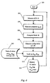
- Figure 6 is a logic flow diagram illustrating the sequential steps implemented by the preferred embodiment of the aircraft non-normalized angle-of-attack indicating system.
- the system starts at 200 and enters a first block 202 at which angle-of-attack, ⁇ , is measured.
- the system in block 204 measures static pressure, P s and total pressure P t .
- the system increments to block 206 in which a Mach value, M, is computed from P s and P t .
- measurements are taken of aircraft configuration, such as landing gear position, g, flap position, f, and speed brake position, sb.
- the system increments to block 210 where, based upon the input values of ⁇ , p s , p t , M, g, f, and sb, the system uses a lookup table, block 212, to look up the limit values for angle-of-attack, such as stick shaker, ⁇ ss , and approach reference angle-of-attack, indicated as ⁇ ref .
- angle-of-attack such as stick shaker, ⁇ ss
- ⁇ ref approach reference angle-of-attack
- step 214 is entered in which appropriate signals are fed to the display to drive the pointer with respect to the gauge to indicate angle-of-attack, and position the first bug ⁇ ss and position the second bug ⁇ ref .
- the system then returns to block 202 to repeat the aforedescribed process.
Landscapes
- Engineering & Computer Science (AREA)
- Radar, Positioning & Navigation (AREA)
- Remote Sensing (AREA)
- Aviation & Aerospace Engineering (AREA)
- Physics & Mathematics (AREA)
- General Physics & Mathematics (AREA)
- Testing Of Devices, Machine Parts, Or Other Structures Thereof (AREA)
- Aiming, Guidance, Guns With A Light Source, Armor, Camouflage, And Targets (AREA)
- Traffic Control Systems (AREA)
Claims (14)
- Anzeigesystem (60) eines nicht normierten Anstellwinkels in einem Flugzeug umfassend:gekennzeichnet durch:ein Messinstrument (30; 40; 104) mit feststehenden Positionsmarkierungen, um einen vorherbestimmten Bereich eines Flugzeuganstellwinkels anzuzeigen;einen Zeiger (32; 42; 102), welcher sich bezüglich des Messinstrumentes (30; 40; 104) auf vorher bestimmte Weise positioniert, um einen Anstellwinkel anzuzeigen;Zeigeransteuerungsmittel (66, 67) zum Bestimmen des aktuellen Flugzeuganstellwinkels (oder) und Positionieren des Zeigers (32; 42; 102) abhängig davon;eine erste Anzeige (34; 44; 106), welche bezüglich der Messinstrumentmarkierungen bewegbar ist, um einen ersten Grenzzustand (αss) für den Flugzeuganstellwinkel zu definieren; undAnzeigeansteuerungsmittel, zum Bestimmen der ersten Grenzposition (αss) eines Flugzeuges und Positionieren der ersten Anzeige (34; 44; 106) abhängig davon,eine zweite Anzeige (36; 46; 118), welche bezüglich der Messinstrumentmarkierungen bewegbar ist, um einen Bereich von akzeptablen Werten für einen Referenzzustand (αref) für den Flugzeuganstellwinkel zu definieren;wobei die Anzeigeansteuerung (76) Mittel (92) zum Bestimmen des Bereiches von akzeptablen Werten der Referenzposition (αref) des Flugzeuganstellwinkels und zum Positionieren der zweiten Anzeige (36; 46; 108) abhängig davon aufweist.
- Anzeigesystem (60) nach Anspruch 1,
dadurch gekennzeichnet, dass die zweite Anzeige (36; 46; 108) einen Anflugreferenzanstellwinkel (αref) des Flugzeuges anzeigt, und
dass die Anzeigesteuerung (76) Mittel (92) besitzt, um einen Anflugreferenzanstellwinkel (αref) des Flugzeuges zu bestimmen und die zweite Anzeige (36; 46; 108) zu positionieren, um denselben anzuzeigen. - Anzeigesystem (60) nach Anspruch 1 oder 2,
dadurch gekennzeichnet, dass die erste Anzeige (34; 44; 106) ein Steuerknüppelrütteln (αss) des Flugzeuges anzeigt; und
dass die Anzeigesteuerung (76, 90) Mittel (90) besitzt, um ein Steuerknüppelrütteln (αss) des Flugzeuges zu bestimmen und die erste Anzeige (34; 44; 106) zu positionieren, um dasselbe anzuzeigen. - Anzeigesystem nach Anspruch 2 oder 3,
dadurch gekennzeichnet, dass die Anzeigesteuerung (76) mit einer Reihe von Konfigurationssensoren (80) verbunden ist und angeordnet ist, um von den Sensoren (80) gemeldete Konfigurationsvariablen zu benutzen, um ein Steuerknüppelrütteln (αss) des Flugzeuges und/oder einen Anflugreferenzanstellwinkel (αref) des Flugzeuges zu bestimmen. - Anzeigesystem (60) nach einem der vorhergehenden Ansprüche,
dadurch gekennzeichnet, dass die Zeigeransteuerungsmittel (66, 76), Mittel zum Erfassen einer Änderungsgeschwindigkeit des Flugzeuganstellwinkels (α) und für eine Beschleunigung des Positionierens des Zeigers (32; 42; 102) abhängig davon besitzen. - Anzeigesystem (60) nach einem der vorhergehenden Ansprüche,
dadurch gekennzeichnet, dass das Messinstrument (30; 104) gebogen ist und feststehende gleichwinklig beabstandete Markierungen des Anstellwinkels von einem vorherbestimmten Minimum zu einem vorherbestimmten Maximum eines Anstellwinkelwertes besitzt;
dass der Zeiger (32; 102) bezüglich einer Seite des Messinstrumentes (30; 104) gebogen positionierbar ist; und
dass die ersten und zweiten Anzeigen (34, 36; 106, 108) bezüglich einer zweiten Seite des Messinstrumentes (30; 104) bogenförmig bewegbar sind. - Anzeigesystem (60) nach einem der Ansprüche 1 bis 5,
dadurch gekennzeichnet, dass das Messinstrument (40) linear ist und feststehende Markierungen des Anstellwinkels von einem vorherbestimmten Minimum zu einem vorherbestimmten Maximum eines Anstellwinkelwertes besitzt;
dass der Zeiger (42) bezüglich einer Seite des Messinstrumentes (40) linear positionierbar ist; und
dass die ersten und zweiten Anzeigen (44, 46) bezüglich einer zweiten Seite des Messinstrumentes (40) linear bewegbar sind. - Verfahren zum Darstellen eines nicht normierten Flugzeuganstellwinkels, umfassend die Schritte:gekennzeichnet durch die weiteren Schritte:a) Bereitstellen eines Messinstrumentes (30; 40; 104) mit feststehenden Positionsmarkierungen, um einen vorherbestimmten Bereich eines Flugzeuganstellwinkels anzuzeigen;b) Bereitstellen eines Zeigers (32; 42; 102), welcher bezüglich des Messinstrumentes (30; 40; 104) auf vorherbestimmte Weise positioniert wird, um den Anstellwinkel anzuzeigen;c) Steuern des Zeigers (32; 42; 102) durch Mittel einer Zeigersteuerung (66, 76) zum Bestimmen des aktuellen Anstellwinkels (α) des Flugzeuges und zum Positionieren des Zeigers (32; 42; 102) abhängig davon;d) Bereitstellen einer bezüglich der Messinstrumentmarkierungen bewegbaren ersten Anzeige (34; 44; 106), um einen ersten Grenzzustand (αss) für den Flugzeuganstellwinkel zu definieren; unde) Bestimmen der ersten Grenzposition (αss) des Flugzeuges und Positionieren der ersten Anzeige (34; 44; 106) abhängig davon,Bereitstellen einer bezüglich der Messinstrumentmarkierungen bewegbaren zweiten Anzeige (36; 46; 108), um einen Bereich von akzeptablen Werten für einen Referenzzustand (αref) für den Flugzeuganstellwinkel zu definieren; undBestimmen des Bereiches von akzeptablen Werten der Referenzposition (αref) des Flugzeuganstellwinkels und Positionieren der zweiten Anzeige (36; 46; 108) abhängig davon.
- Verfahren nach Anspruch 8, gekennzeichnet durch die weiteren Schritte:Bereitstellen der zweiten Anzeige (36; 46; 108) als Anzeige eines Anflugreferenzanstellwinkels (αref) des Flugzeuges; undBestimmen des Anflugreferenzanstellwinkels (αref) des Flugzeuges und Positionieren der zweiten Anzeige (36; 46; 108), um denselben anzuzeigen.
- Verfahren nach Anspruch 8 oder 9, gekennzeichnet durch die weiteren Schritte:Bereitstellen der ersten Anzeige (34; 44; 106) als Anzeige eines Anstellwinkels (αss) eines Steuerknüppelrüttelns des Flugzeuges; undBestimmen des Anstellwinkels (αss) des Steuerknüppelrüttelns des Flugzeuges und Positionieren der ersten Anzeige (34; 44; 106), um denselben anzuzeigen.
- Verfahren nach Anspruch 9 oder 10, gekennzeichnet durch die weiteren Schritte,
Bereitstellen einer Reihe von mit der Anzeigesteuerung (76) verbundener Konfigurationssensoren (80) und Benutzen von von den Sensoren (80) gemeldeten Konfigurationsvariablen, um ein Steuerknüppelrütteln (αss) des Flugzeuges und/oder den Anflugreferenzanstellwinkel (αref) des Flugzeuges zu bestimmen. - Verfahren nach einem der Ansprüche 8 bis 11, gekennzeichnet durch die weiteren Schritte,
Erfassen der Änderungsgeschwindigkeit des Flugzeuganstellwinkels (α) und Beschleunigen des Positionierens des Zeigers (32; 42; 102) abhängig davon. - Verfahren nach einem der Ansprüche 8 bis 12, gekennzeichnet durch die weiteren Schritte:Bereitstellen des Messinstrumentes (30; 104) als gebogen mit feststehenden Markierungen des Anstellwinkels von einem vorherbestimmten Minimum zu einem vorherbestimmten Maximum eines Anstellwinkelwertes;
bogenförmiges Positionieren des Zeigers (32; 102) bezüglich einer Seite des Messinstrumentes; und
bogenförmiges Bewegen der ersten und zweiten Anzeigen (34, 36; 106, 108) bezüglich der zweiten Seite des Messinstrumentes (30; 104). - Verfahren nach einem der Ansprüche 8 bis 12, gekennzeichnet durch die weiteren Schritte:Bereitstellen des Messinstrumentes (40) als linear mit feststehenden Markierungen des Anstellwinkels von einem vorherbestimmten Minimum zu einem vorherbestimmten Maximum eines Anstellwinkelwertes;linear Positionieren des Zeigers (42) bezüglich einer Seite des Messinstrumentes (40); undlinear Bewegen der ersten und zweiten Anzeigen (44, 46) bezüglich einer zweiten Seite des Messinstrumentes (40).
Applications Claiming Priority (2)
| Application Number | Priority Date | Filing Date | Title |
|---|---|---|---|
| US09/209,348 US6131055A (en) | 1998-12-11 | 1998-12-11 | Aircraft non-normalized angle-of-attack indicating system |
| US209348 | 2002-07-31 |
Publications (2)
| Publication Number | Publication Date |
|---|---|
| EP1008921A1 EP1008921A1 (de) | 2000-06-14 |
| EP1008921B1 true EP1008921B1 (de) | 2003-07-02 |
Family
ID=22778415
Family Applications (1)
| Application Number | Title | Priority Date | Filing Date |
|---|---|---|---|
| EP99203493A Revoked EP1008921B1 (de) | 1998-12-11 | 1999-10-25 | Einrichtung zur Anzeige des Anstellwinkels in einem Flugzeug |
Country Status (3)
| Country | Link |
|---|---|
| US (1) | US6131055A (de) |
| EP (1) | EP1008921B1 (de) |
| DE (1) | DE69909221T2 (de) |
Families Citing this family (14)
| Publication number | Priority date | Publication date | Assignee | Title |
|---|---|---|---|---|
| WO2000065423A2 (en) * | 1999-04-01 | 2000-11-02 | Price Ricardo A | Electronic flight instrument displays |
| US6772976B1 (en) | 2002-04-10 | 2004-08-10 | Honeywell International, Inc. | Sensor for measuring wind angle |
| FR2852689B1 (fr) | 2003-03-20 | 2005-06-10 | Airbus France | Procede et indicateur pour afficher des informations illustrant des marges de vitesse sur un aeronef |
| US7043345B2 (en) * | 2003-10-10 | 2006-05-09 | Raytheon Company | System and method with adaptive angle-of-attack autopilot |
| US8408871B2 (en) * | 2008-06-13 | 2013-04-02 | General Electric Company | Method and apparatus for measuring air flow condition at a wind turbine blade |
| US8878700B2 (en) * | 2013-02-18 | 2014-11-04 | The Boeing Company | Aircraft monitoring system |
| US9221550B2 (en) * | 2013-03-12 | 2015-12-29 | Geoffrey S. M. Hedrick | Composite normalized angle of attack indicating system |
| CA2920449C (en) * | 2013-08-08 | 2021-12-28 | Bombardier Inc. | Air data probe contamination monitor |
| US9193473B2 (en) * | 2013-09-20 | 2015-11-24 | Safe Flight Instrument Corporation | Angle of attack display |
| CA3029131A1 (en) * | 2016-06-29 | 2018-01-04 | L-3 Technologies Avionic Products | Intuitive display of angle of attack guidance on aircraft attitude indicator |
| FR3074141B1 (fr) * | 2017-11-27 | 2019-12-20 | Airbus Operations | Procede et systeme d'estimation de la position de volets d'un aeronef |
| US11029706B2 (en) * | 2018-12-07 | 2021-06-08 | The Boeing Company | Flight control system for determining a fault based on error between a measured and an estimated angle of attack |
| US11066189B2 (en) | 2018-12-07 | 2021-07-20 | The Boeing Company | Flight control system for determining estimated dynamic pressure based on lift and drag coefficients |
| US11003196B2 (en) | 2018-12-07 | 2021-05-11 | The Boeing Company | Flight control system for determining a common mode pneumatic fault |
Family Cites Families (31)
| Publication number | Priority date | Publication date | Assignee | Title |
|---|---|---|---|---|
| US2352955A (en) * | 1944-07-04 | Angle of attack indicator | ||
| US2237306A (en) * | 1939-09-09 | 1941-04-08 | Manley J Hood | Angle-of-attack indicator |
| US2499284A (en) * | 1947-04-29 | 1950-02-28 | Hubert A Smith | Airplane stall indicator |
| US2986033A (en) * | 1955-01-31 | 1961-05-30 | Aerotec Ind Inc | Angle of attack instrumentation for aircraft |
| US2941400A (en) * | 1955-09-29 | 1960-06-21 | James O Nesbitt | Pilot's flight control indicator |
| US3587311A (en) * | 1969-06-19 | 1971-06-28 | Teledyne Inc | Aircraft instrument system |
| US3614036A (en) * | 1969-10-13 | 1971-10-19 | Collins Radio Co | Conversion principle-angle of attack to airspeed |
| US3654443A (en) * | 1969-11-03 | 1972-04-04 | Sperry Rand Corp | Angle-of-attack computer |
| US3686936A (en) * | 1970-02-11 | 1972-08-29 | Charles H Daudt Jr | Method and apparatus for detecting stall buffet |
| US3686626A (en) * | 1970-06-03 | 1972-08-22 | United Control Corp | Aircraft instrument |
| US3654806A (en) * | 1970-06-18 | 1972-04-11 | Sundstrand Data Controls Inc | Aircraft instrument |
| US3814912A (en) * | 1973-01-04 | 1974-06-04 | Collins Radio Co | Gust compensation for angle-of-attack reference aircraft speed control system |
| US4040005A (en) * | 1974-12-23 | 1977-08-02 | Melvin William W | Composite situation analyzer and instrument flight system |
| US3970829A (en) * | 1974-12-23 | 1976-07-20 | Melvin William W | Composite situation analyzer and instrument flight system |
| US4044975A (en) * | 1976-05-17 | 1977-08-30 | Mcdonnell Douglas Corporation | Aircraft speed command system |
| US4027533A (en) * | 1976-06-23 | 1977-06-07 | John Pretto | Angle of attack indicating device |
| US4230290A (en) * | 1978-05-01 | 1980-10-28 | Townsend Engineering Company | Airplane angle of attack and direction of flight indicator |
| US4247843A (en) * | 1978-08-23 | 1981-01-27 | Sperry Corporation | Aircraft flight instrument display system |
| US4235104A (en) * | 1979-03-19 | 1980-11-25 | The Board Of Trustees Of Western Michigan University | Normalized coefficient of lift indicator |
| US4468961A (en) * | 1980-10-17 | 1984-09-04 | Berg Lauren V | Fluid direction meter suitable for angle of attack meter for aircraft |
| US4390950A (en) * | 1980-11-28 | 1983-06-28 | Sundstrand Corporation | Angle of attack based pitch generator and head up display |
| US4583094A (en) * | 1983-04-28 | 1986-04-15 | Rockwell International Corporation | Solid state attitude director indicator |
| US5016177A (en) * | 1983-05-31 | 1991-05-14 | The Boeing Company | Aircraft flight path angle display system |
| US4908619A (en) * | 1984-11-13 | 1990-03-13 | The Boeing Company | Aircraft stall warning system |
| US4910513A (en) * | 1985-11-20 | 1990-03-20 | The Boeing Company | Apparatus and methods for generating a stall warning margin on an aircraft attitude indicator display |
| US4786905A (en) * | 1986-03-26 | 1988-11-22 | Sundstrand Data Control, Inc. | Wind shear detector head-up display system |
| GB8609931D0 (en) * | 1986-04-23 | 1986-09-17 | Gec Avionics | Aircraft display devices |
| US5003305A (en) * | 1988-10-24 | 1991-03-26 | The Boeing Company | Apparatus and method for displaying aircraft flight path angle on an attitude display indicator |
| US4909077A (en) * | 1989-07-14 | 1990-03-20 | Safe Flight Instrument Company | Settable indexing device for aircraft angle of attack indicator meter |
| US5089968A (en) * | 1990-01-26 | 1992-02-18 | The Boeing Company | Ground effects compensated real time aircraft body angle of attack estimation |
| US5803408A (en) * | 1995-05-15 | 1998-09-08 | The Boeing Company | Autopilot/flight director stall protection system |
-
1998
- 1998-12-11 US US09/209,348 patent/US6131055A/en not_active Expired - Lifetime
-
1999
- 1999-10-25 EP EP99203493A patent/EP1008921B1/de not_active Revoked
- 1999-10-25 DE DE69909221T patent/DE69909221T2/de not_active Revoked
Also Published As
| Publication number | Publication date |
|---|---|
| EP1008921A1 (de) | 2000-06-14 |
| DE69909221T2 (de) | 2004-05-27 |
| DE69909221D1 (de) | 2003-08-07 |
| US6131055A (en) | 2000-10-10 |
Similar Documents
| Publication | Publication Date | Title |
|---|---|---|
| US6131055A (en) | Aircraft non-normalized angle-of-attack indicating system | |
| CA2969765C (en) | System and method for dynamically determining and indicating an aircraft bank limit on an aircraft instrument panel | |
| US5412382A (en) | Integrated electronic primary flight display | |
| EP2715287B1 (de) | Spitzen- und leistungsbasierte unzuverlässige luftgeschwindigkeitssymbologie für eine primäre fluganzeige | |
| EP1936386B1 (de) | Luftdatenbasiertes Strömungsabriss-Schutzsystem | |
| EP2402716B1 (de) | Verfahren und System zur Markierung einer Bilddarstellung eines Flugparameters eines Flugzeuges | |
| US9174742B2 (en) | Assistance with piloting of an aircraft in a stall | |
| EP3280645B1 (de) | System und verfahren zur anstellwinkelanzeige ohne eigene sensoren und luftfahrzeuginformationen | |
| US11299289B1 (en) | Angle-of-attack determination for aircraft stall protection | |
| EP2778070B1 (de) | Gemischtes normiertes Anstellwinkelanzeigesystem | |
| US6982655B2 (en) | Method and indicator for displaying information showing the airspeed tolerance margins for an aircraft | |
| CN100547353C (zh) | 电子非线性航空器动态参数显示器 | |
| WO1987006043A1 (en) | Wind shear detector head-up display system | |
| WO1998041911A1 (en) | Altitude alert system for aircraft operating in reduced vertical separation minimum airspace and method therefor | |
| US6400283B1 (en) | Altitude and vertical speed indicator for aircraft | |
| US6933859B2 (en) | Lateral acceleration indicator for aircraft | |
| US7412308B2 (en) | Dynamic VSI display | |
| US7095338B2 (en) | TCAS VSI display | |
| US20070067690A1 (en) | Dynamic miscompare | |
| EP0545920A1 (de) | Anzeigegerät für ein flugzeug | |
| Derajat et al. | N 250-PA 1 in-flight low speed pitot static, angle of sideslip and angle of attack calibrations using Inertial Navigation System(INS) | |
| WO2006041479A1 (en) | Dynamic vsi display |
Legal Events
| Date | Code | Title | Description |
|---|---|---|---|
| PUAI | Public reference made under article 153(3) epc to a published international application that has entered the european phase |
Free format text: ORIGINAL CODE: 0009012 |
|
| AK | Designated contracting states |
Kind code of ref document: A1 Designated state(s): DE FR GB |
|
| AX | Request for extension of the european patent |
Free format text: AL;LT;LV;MK;RO;SI |
|
| 17P | Request for examination filed |
Effective date: 20001212 |
|
| AKX | Designation fees paid |
Free format text: DE FR GB |
|
| 17Q | First examination report despatched |
Effective date: 20010710 |
|
| GRAH | Despatch of communication of intention to grant a patent |
Free format text: ORIGINAL CODE: EPIDOS IGRA |
|
| GRAH | Despatch of communication of intention to grant a patent |
Free format text: ORIGINAL CODE: EPIDOS IGRA |
|
| GRAA | (expected) grant |
Free format text: ORIGINAL CODE: 0009210 |
|
| AK | Designated contracting states |
Designated state(s): DE FR GB |
|
| REG | Reference to a national code |
Ref country code: GB Ref legal event code: FG4D |
|
| REF | Corresponds to: |
Ref document number: 69909221 Country of ref document: DE Date of ref document: 20030807 Kind code of ref document: P |
|
| PLBI | Opposition filed |
Free format text: ORIGINAL CODE: 0009260 |
|
| PLBQ | Unpublished change to opponent data |
Free format text: ORIGINAL CODE: EPIDOS OPPO |
|
| ET | Fr: translation filed | ||
| PLAX | Notice of opposition and request to file observation + time limit sent |
Free format text: ORIGINAL CODE: EPIDOSNOBS2 |
|
| 26 | Opposition filed |
Opponent name: AIRBUS SAS Effective date: 20040402 |
|
| PLAX | Notice of opposition and request to file observation + time limit sent |
Free format text: ORIGINAL CODE: EPIDOSNOBS2 |
|
| PGFP | Annual fee paid to national office [announced via postgrant information from national office to epo] |
Ref country code: GB Payment date: 20041020 Year of fee payment: 6 Ref country code: FR Payment date: 20041020 Year of fee payment: 6 |
|
| PGFP | Annual fee paid to national office [announced via postgrant information from national office to epo] |
Ref country code: DE Payment date: 20041130 Year of fee payment: 6 |
|
| RDAF | Communication despatched that patent is revoked |
Free format text: ORIGINAL CODE: EPIDOSNREV1 |
|
| RDAG | Patent revoked |
Free format text: ORIGINAL CODE: 0009271 |
|
| STAA | Information on the status of an ep patent application or granted ep patent |
Free format text: STATUS: PATENT REVOKED |
|
| 27W | Patent revoked |
Effective date: 20050626 |
|
| GBPR | Gb: patent revoked under art. 102 of the ep convention designating the uk as contracting state |
Free format text: 20050626 |