EP1008941B1 - Procédé de commande de communication, dispositif de commande de communication et support d'enregistrement - Google Patents
Procédé de commande de communication, dispositif de commande de communication et support d'enregistrement Download PDFInfo
- Publication number
- EP1008941B1 EP1008941B1 EP99309904A EP99309904A EP1008941B1 EP 1008941 B1 EP1008941 B1 EP 1008941B1 EP 99309904 A EP99309904 A EP 99309904A EP 99309904 A EP99309904 A EP 99309904A EP 1008941 B1 EP1008941 B1 EP 1008941B1
- Authority
- EP
- European Patent Office
- Prior art keywords
- command
- target
- initiator
- orb
- queue
- Prior art date
- Legal status (The legal status is an assumption and is not a legal conclusion. Google has not performed a legal analysis and makes no representation as to the accuracy of the status listed.)
- Expired - Lifetime
Links
Images















Classifications
-
- H—ELECTRICITY
- H04—ELECTRIC COMMUNICATION TECHNIQUE
- H04L—TRANSMISSION OF DIGITAL INFORMATION, e.g. TELEGRAPHIC COMMUNICATION
- H04L12/00—Data switching networks
- H04L12/28—Data switching networks characterised by path configuration, e.g. LAN [Local Area Networks] or WAN [Wide Area Networks]
- H04L12/40—Bus networks
- H04L12/40052—High-speed IEEE 1394 serial bus
- H04L12/40123—Interconnection of computers and peripherals
-
- G—PHYSICS
- G06—COMPUTING OR CALCULATING; COUNTING
- G06F—ELECTRIC DIGITAL DATA PROCESSING
- G06F13/00—Interconnection of, or transfer of information or other signals between, memories, input/output devices or central processing units
- G06F13/10—Program control for peripheral devices
- G06F13/12—Program control for peripheral devices using hardware independent of the central processor, e.g. channel or peripheral processor
- G06F13/122—Program control for peripheral devices using hardware independent of the central processor, e.g. channel or peripheral processor where hardware performs an I/O function other than control of data transfer
Definitions
- the invention relates to communication control method and system for connecting equipment such as initiator (host computer) and target (printer or the like).
- the IEEE1394 interface is being used to connect a computer and peripheral equipment or connect both peripheral equipment.
- the IEEE1394 interface has a processing speed higher than that of the hand shaking system such as a centronics interface or the like and can perform a bidirectional communication.
- the IEEE1394 interface is also an interface for a memory bus model and equipment connected by it can read or write data at a designated address from/to partner's equipment.
- a protocol for a physical layer and a link layer to apply it in a wide range is determined, a detailed protocol for each equipment is not decided. Therefore, a protocol for a transport layer such as SBP (Serial Bus Protocol)-2 or the like using IEEE1394 has been proposed as physical/link layers.
- the transport layer is a layer which provides a data transmitting function for an application. The applications using such a layer can mutually exchange data.
- the SBP-2 protocol is a protocol utilizing a feature as a memory bus model of IEEE1394, and the reception side of data can receive the data in accordance with circumstances of itself.
- protocols other than SBP-2 there are a protocol which can transmit data which is asynchronously generated and a protocol which can realize multichannels.
- protocols cannot utilize the feature as a memory bus model of IEEE1394. That is, in case of a communication between a host and a printer, data transmission cannot be performed in accordance with circumstances on the printer side and the host has to perform the data transmission while monitoring a status of the printer.
- an operation called "login” is first performed on the transmission side, thereby establishing a channel with a communication partner.
- the login side is called an initiator and the partner side connected to the initiator is called a target.
- the data transmission is performed by reading or writing data from/into a buffer of the initiator from the target in accordance with an instruction from the initiator.
- the initiator forms an ORB (Operation Request Block) in which an address, a size, and the like of the buffer in which the data to be transmitted has been stored have been written and notifies the target of the address of the ORB.
- the target reads out or writes the data from/to the initiator on the basis of the address and size written in the ORB in accordance with its own circumstances, forms a status block after completion of those processes, and notifies the initiator of states of the processes.
- the data transmission is fundamentally managed by the initiator and the target cannot perform the asynchronous data transmission to the initiator. That is, in SBP-2, when the target wants to transmit data to the initiator, it sends a data reading request to the initiator in an unsolicited status.
- the initiator forms an ORB in response to it and includes the formed ORB into the end of a list of the pending ORBs (a data transmission request from the initiator to the target and the like are included).
- the data is transmitted from the target to the initiator for the first time when the process of the ORB on the initiator side is progressed and the ORB processes in response to the data reading request from the target instead of a timing when the target issues the reading request to the initiator. That is, in the case where the bidirectional asynchronous data transmission cannot be performed and the data to be transmitted from the target to the initiator is asynchronously generated, for example, assuming that the target is a printer, in the case where an error occurs in the printer, or the like, the data to be transmitted immediately to the initiator cannot be momentarily transmitted.
- a login procedure has to be performed by using the printer as an initiator and a data transmission in which the host computer is used as a target has to be performed.
- a hybrid apparatus in which various functions are combined as peripheral apparatuses is being used.
- a digital hybrid apparatus or the like such that a facsimile apparatus is used as a scanner unit apparatus, a printer unit apparatus, and a facsimile and can be used from the host computer or the like.
- a hybrid apparatus if a communication is performed through a plurality of independent channels with one for every unit apparatus function, a plurality of functions can be simultaneously used.
- a bus reset occurs when a status change which becomes a cause of a change of a network construction such that new equipment is connected to a 1394 serial bus or the equipment is disconnected or a power source of the connected equipment is turned on or off occurs.
- the bus reset occurs when a node which detects the status change as mentioned above on the bus transmits a bus resetting signal onto the bus.
- the generated bus resetting signal is transmitted from one node to another.
- the bus reset occurs asynchronously with the process in a node on a network. Even in case of a node which is not concerned with a node which becomes a cause of the bus reset with respect to the application, if the bus reset has once occurred, a bus resetting process has to be performed. In the bus resetting step, in the node which performs a communication by SBP-2, the set connection is disconnected. Even if it is re-connected, a guarantee such that the process can be continued from the state just before the bus reset is not given.
- EP-A-0578013 discloses the transfer of information between functional units via virtual channels whose status is controlled by a connection manager.
- the status of a channel can be closed by the connection manager communicating between the units via dedicated channels reserved for its use, the closed channel being returned to a pool of free channels for reuse.
- the invention is made in consideration of the above conventional technique and it is a invention to provide a communication control method and apparatus which enables full duplex communication (mutually asynchronous bidirectional communication) to be performed by a single login and which can efficiently use resources such as processes and memories necessary for exchanging data.
- Another concern of the invention is to provide a communication control method and apparatus for realizing multichannels which can be managed on a unit basis of a channel or a path.
- Still another concern of the invention is to provide a communication control method and apparatus which guarantee the continuation of processes from a state just before a bus reset even if the bus reset occurs.
- Another concern of the invention is to provide a communication control method and apparatus which can efficiently use resources by unitarily managing the number of commands which can be transmitted from an initiator to a target instead of managing each queue of the target.
- Another concern of the invention is to provide a communication control method and apparatus in which an initiator dynamically performs an allocation to all command pool areas of a target in a multiplex path by queues, thereby improving communicating efficiency and resource using efficiency of the target, and the number of command pool areas of the target is increased or decreased in accordance with the number of queues which are used for connection, thereby improving the resource using efficiency of the target.
- Fig. 24 is a constructional diagram of hardware in the printer system.
- a host computer 200 has a CPU 1 for executing processes of a document in which a figure, an image, characters, a table (including a spreadsheet or the like), and the like mixedly exist on the basis of a document processing program or the like stored in a program ROM of an ROM 3.
- the CPU 1 integratedly controls each device connected to a system bus 4.
- a control program and the like of the CPU 1 are stored in the program ROM of the ROM 3. Font data and the like which is used in the document process is stored in a font ROM of the ROM 3.
- Various data which is used when the document process or the like is executed is stored in a data ROM of the ROM 3.
- a RAM 2 functions as a main memory, a work area, or the like of the CPU 1.
- the programs can be also stored in the RAM 2.
- a transmission data buffer or a system memory to store an ORB is assured in the RAM 2.
- a keyboard controller (KBC) 5 controls a key input from a keyboard 9 or a pointing device (not shown).
- a CRT controller (CRTC) 6 controls a display on a CRT display (CRT) 10.
- a memory controller (MC) 7 controls an access to an external memory 11 such as hard disk (HD), floppy disk (FD), or the like to store a boot program, various applications, font data, a user file, an edit file, and the like.
- a 1394 interface 8 is connected to a printer 100 and executes a communication control process of a communication with the printer 100 in accordance with the IEEE1394 standard.
- the CPU 1 executes a developing (rasterizing) process of an outline font into a display information RAM set on the RAM 2, thereby enabling WYSIWYG on the CRT 10.
- the CPU 1 opens various registered windows on the basis of commands instructed by a mouse cursor or the like (not shown) on the CRT 10 and executes various data processes.
- a printer CPU 12 integratedly controls accesses to various devices connected to a system bus 15 on the basis of a control program stored in a program ROM of an ROM 13, a control program stored in an external memory 14, or the like, and outputs an image signal as output information to a printing unit (printer engine) 17 connected through a printing unit interface (engine interface) 16.
- Various agents which will be explained hereinlater, a control program for the CPU 12 to realize image processes, and the like are stored in the program ROM of the ROM 13. Font data and the like which are used when the output information is formed are stored in a font ROM of the ROM 13.
- a printer without the external memory 14 such as a hard disk or the like information and the like which are used on the host computer are stored in a data ROM of the ROM 13.
- the CPU 12 can execute a communicating process of a communication with the host computer through a 1394 interface 18 and notify the host computer 200 of information or the like in the printer.
- An RAM 19 functions as a main memory, a work area, or the like of the CPU 12 and is constructed so that a memory capacity can be expanded by an option RAM which is connected to an expanding port (not shown).
- the RAM 19 is used as an output information rasterizing area, an environmental data memory area, an NVRAM, or the like.
- An access to the external memory 14 such as hard disk (HD), IC card, or the like mentioned above is controlled by a memory controller (MC) 20.
- the external memory 14 is connected as an option and stores font data, an emulation program, form data, and the like. Switches for operation, an LED display, and the like are arranged on an operation panel 1002.
- the number of external memories is not limited to 1.
- the apparatus can be also constructed in a manner such that at least one or more external memories are provided and an option font card in addition to built-in fonts and a plurality of external memories in which programs to interpret printer control languages of different language systems have been stored can be connected. Further, the apparatus can have an NVRAM (not shown) and store printer mode set information from the operation panel 1002.
- finisher having a stapler function, a sorter function, and the like can be also connected.
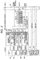
- Figs. 1 and 2 show communication systems in which the printer 100 is used as a target and the host computer 200 is used as an initiator. In the embodiment, those constructions are realized by executing programs by CPUs in the host computer and the printer, respectively. First, the initiator in Fig. 2 will be described.
- a client 206 such as a printer driver or the like issues a data transmission request for a printer through an SHPT-2 processor 201 and receives a response from the printer.
- the SHPT-2 processor 201 manages management request queues, I/O request queues, and ORBs which are formed in the system memory.
- the client 206 comprises one or a plurality of client processes.
- the I/O request command from each client process is queued into each I/O request queue which is used for communication of each client process. Although four I/O request queues are shown as an example in the diagram, the number of I/O request queues is not limited to 4.
- the I/O request queue is dynamically prepared at the time of a connection of a communication of each client process. One or a plurality of I/O request queues are used for communication of each client process.
- two I/O request queues 202a and 202b are used for communication of a client process 206a.
- a write request command from the client process 206a is queued into the I/O request queue 202a.
- a read request command from the client process 206a is queued into the I/O request queue 202b.
- a state where an asynchronous full duplex communication is performed by those two I/O request queues is shown.
- an I/O request queue 202c is used for communication of a client process 206b.
- a write request command is queued into the I/O request queue 202c and a unidirectional communication is performed.
- An I/O request queue 202d is used for communication of a client process 206c.
- a state where a synchronous semi duplex communication is performed by queueing one or both of the write request command and read request command into the I/O request queue 202d is shown.
- the management request queue is formed at the time of login to the initiator.
- a forming procedure itself is substantially the same as that of an I/O request queue, which will be explained hereinlater.
- the management request queue is a queue provided to manage the I/O request queue.
- a management path is constructed by a pair of the management request queue and a management reference queue, which will be explained hereinlater.
- the management request queue is used to process a specific request for the other I/O request queue. An example of using the management request queue will be described hereinlater.
- the I/O request queue and the management request queue are managed by a queue management agent (not shown).
- ORB is a block in which an address, a size, and the like of a data buffer which are sent from the host computer as an initiator to the printer as a target or from the printer to the host computer have been stored.
- the blocks are sequentially linked to an ORB list 204 from the head ORB.
- ORB there are the following processing rules.
- the SHPT-2 processor 201 prepares one counter for each request queue and one counter for the prefetch pool, respectively.
- a counter for each I/O request queue is a counter called Current-QUE.
- Current-QUE Current-QUE counters 203a, 203b, 203c, and 203d for four I/O request queues and a counter 203f for the management queue are shown.
- each Current-QUE counter the number of reserved areas in the prefetch pool allocated to the respective I/O request queues is held in the denominator (right side).
- the number of commands (in the current ORB list) belonging to the I/O request queue is held in the numerator (left side).
- the example in the diagram shows a state where the number of reserved areas in the prefetch pool allocated to the I/O request queues is equal to "1" and the numbers of commands (in the current ORB list) belonging to the I/O request queues 202a, 202b, 202c, and 202d and the management queue 203f are equal to "3", "1", "0", "2", and "0" respectively.
- a counter for the prefetch pool is a counter 203e called Current-POOL.
- This counter indicates the number of free areas in the prefetch pool other than the reserved areas allocated to the I/O request queues.
- the example in the diagram shows a state where the number of free areas in the prefetch pool other than the reserved areas allocated to the I/O request queues is equal to "5".
- the total number of areas in the prefetch pool is held by the equipment as a target. This value is read out from the target at the time of login or the like and stored into the initiator.
- the example in the diagram shows a state where the total number of areas in the prefetch pool is equal to "10".
- the number (in the current ORB list) in the Current-QUE counter associated with the I/O request queue is increased or decreased in accordance with the formation and deletion of the ORB.
- the number in the Current-QUE counter namely, the number (in the current ORB list) of commands does not exceed the number of reserved areas in the prefetch pool allocated to the I/O request queues at the initial stage, the number in the Current-QUE counter is increased and the ORB is added into the ORB list. Otherwise, a check is made to see if the number in the Current-POOL counter is equal to or larger than "1". If it is equal to or larger than "1", the number in the Current-POOL counter is decreased, the number in the Current-QUE counter is increased, and the ORB is added into the ORB list. If the number in the Current-POOL counter is already equal to "0", the ORB is not added into the ORB list.
- a predetermined value is written into a register called a doorbell register on the target side or the address of the ORB at the head of the list is written into a register called an ORB pointer, thereby notifying the target of the generation of the ORB. If the ORB has already been added to the end of the ORB list which is being executed by the target, the predetermined value is written into the doorbell register.
- the head ORB is newly formed in a state without an ORB list, the address is written into the ORB pointer. This procedure is specified in SBP-2.
- the SHPT-2 processor 201 includes a status FIFO 205.
- the status received through a 1394 interface 109 is processed by the SHPT-2 processor 201.
- the SHPT-2 processor 201 removes the ORB corresponding to the received status from the ORB list 204 and removes the command corresponding to the removed ORB from the I/O request queue.
- the command can be written from the initiator to the management register of the target. Since this writing is specified in the SBP-2 and is out of a management range of the SHPT-2 layer, its detailed description is omitted.
- the writing to the management register is used for management of SBP-2.
- the host computer as an initiator has the functional construction as mentioned above.
- Fig. 1 is a block diagram showing a functional construction of the printer as a target.
- a doorbell register 101a is a register in which a value is written by the initiator and shows that the ORB has newly been formed. The address of the newly formed ORB is written into an ORB pointer 101b by the initiator.
- a fetch agent 101 reads out the ORB shown by the ORB pointer through the 1394 interface 109.
- An ORB dispatcher 102 extracts a pointer from a free reference list 104, stores the command of the ORB read by the fetch agent 101 into free areas (Fr-1 to Fr-4) in a prefetch pool 103 shown by the pointer, and connects the pointer to the end of the reference queue in accordance with a "QueueID" field, which will be explained hereinlater, of the relevant ORB.
- the example in the diagram shows a state where four reference queues 105a, 105b, 105c, and 105d and a management reference queue 105f exist.
- the number of reference queues is not limited to 4.
- the reference queues are dynamically prepared when a communication of each client process is connected.
- One or a plurality of reference queues are used for communication of each client process.
- An execution agent 106 fetches the commands queued into each reference queue from the head, performs the writing of data into the buffer of the initiator, the reading of the data from the buffer of the initiator, or the like in accordance with commands, and after that, returns a normal status to the host computer.
- one execution thread can independently schedule and execute the processes for all of the reference queues so as not to be blocked by the processes of the other reference queues, or the threads can be scheduled and executed by another execution thread for each reference queue. Or, a combination of those executing methods can be used.
- the execution agent 106 writes the data into the buffer of the initiator designated by a read command in the prefetch pool which is referred to by the reference queue 105b in response to a data transmission request from a client process 108a such as a rasterizer or the like for interpreting, for example, a PDL and forming raster data.
- a bus interface 110 is an interface for accessing from the printer 100 as a target to a desired memory location in a system memory 208 of the host computer 200 as an initiator.
- a management register 110 is a register to write the management ORB as a command from the initiator. This management ORB is processed by a management register execution agent. An AbortTaskSet command, which will be explained hereinlater, and the like are written into this register.
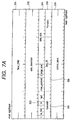
- Figs. 7A and 7B are diagrams showing a general construction of the ORB.
- a "Next_ORB" (link) field 301 is a link to the next ORB.
- a "data_descriptor” field 302 shows an address in a data buffer.
- a “d" (direction) field 303 shows a data transmission (0: write) from the host computer to the printer or a data transmission (1: read) from the printer to the host computer.
- a “data_size” field 304 indicates a size of data buffer shown by the address field 302.
- the fields (also including fields which are not described yet) locating above a dotted line in the diagram are the fields specified by SBP-2 and fields 305 to 308 which will be described from now on are fields which are used for processes peculiar to SHPT-2.
- the "QueueID” field 305 indicates an ID of a reference queue which is used.
- the "function” field 306 indicates a kind of ORB as shown in Fig. 7B. OH indicates the write command. 40H indicates the read command.
- the "seq_ID" (sequence ID) field 308 indicates a sequential identifier which is allocatedto each reference queue in forming order of the ORBs. In the embodiment, the identifier is given so as to increase each time the ORB is formed.
- a counter which gives a value to the sequence ID field and serves as a reference is provided in a region where it is not influenced by the bus reset or another obstacle. This is because the processes are performed in the target while increase performance of the sequence ID is used as a prerequisite.
- Various values are inputted into a control block field 309 in accordance with the value in the function field 306 or a function which is realized by the target for each function. The address and size of the buffer are obtained at the time of formation of the ORB from the command inputted in the I/O request queue.
- This command is a command to send the data in the designated buffer from the initiator to the target.
- a value in the function field is equal to "OH”.
- the "t" (tag) bit 307 shows a data tag.
- This command is a command to read out the data from the target by the initiator.
- a value in the function field is equal to 40H.
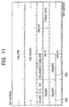
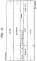
- An ID of a service of a new connection destination is designated in a "Service_ID” field 309a.
- Information indicating that to which one of the full duplex bidirection, unidirection, and semi duplex bidirection the connection is set is designated in a "Mode" field 309b.
- An "i” bit 309e is set to 1 when the initiator requests an increase in the prefetch pool to the target.
- This command is used to close the connection opened by the connection command ORB.
- 0 is designated in the "QueueID2" field.
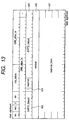
- Fig. 13 shows a format and contents of a status which is returned from the target to the initiator.
- the fields locating above a dotted line are the fields specified by SBP-2, they are not described in particular.
- a tag field 404 shows a data tag and is valid only in the status for the read command ORB.
- SHPT2_status1 and “SHPT2_status2” are fields showing an execution result status of the command ORB and indicate an error when they are other than 0. That is, when the value is equal to 0, this means that the processes with respect to the command ORB corresponding to such a status have been completed. For example, when the corresponding command ORB is the write command, this means that as for the status block in which the SHPT-2 status is equal to 0, the target reads out all of the data from the buffer indicated by the corresponding write command ORB and finishes the writing into the buffer which the target has. When the value is other than 0, this means that a part or all of the processes of the corresponding command ORB are not performed due to the error. The initiator which received this error copes with the error by notifying the client of the occurrence of the error, or the like.
- a "residual" (remain) field 406 shows a residual data length excluding a length of data processed for the buffer indicated by the ORB.
- the IDs of the reference queues which are used for new connection are shown in a "QueueID1" field 407a and a "QueueID2" field 407b.
- a "Mode" field of the connection command ORB indicates the unidirection, 0 is returned to "QueueID2".
- the same ID is returned to "QueueID1" and “QueueID2".
- the bidirection different IDs are returned to "QueueID1" and "QueueID2".
- a "POOL_Inc" field 407c indicates an increase amount of the capacity of the prefetch pool of the target.
- the client When a data transmission request from the client of the initiator is issued, the client includes the write command including the address and size of the buffer in which the data to be sent to the target has been stored to the end of the I/O request queue A 202a.
- a check is made to see if the number of commands (in the current ORB list) belonging to the I/O request queue shown by the Current-QUE counter 203a is equal to or larger than the number of reserved areas in the prefetch pool allocated to the I/O request queue. If it is equal to or less than the number of reserved areas, an ORB is formed from the write command and linked to the end of the ORB list 204. The number of commands (in the current ORB list) belonging to the I/O request queue shown by the Current-QUE counter 203a is increased by 1. If the number in the ORB list is equal to or larger than the number of reserved areas, the Current-POOL counter 203e is checked.
- an ORB is formed from the write command and linked to the end of the ORB list 204.
- the number of commands (in the current ORB list) belonging to the I/O request queue shown by the Current-QUE counter 203a is increased by 1 and the value of the Current-POOL counter is decreased by 1.
- the Current-POOL counter 203e is checked and if there is no free area, the apparatus waits for the free area.
- three ORBs have already been linked from the request queue A and this number is larger than the number 1 of reserved areas.
- the value in the Current-POOL counter is equal to 3
- the value in the Current-POOL counter is reduced to 2 and the number in the ORB list of the Current-QUE counter is increased to 4.
- the ORB for a writing request Qa-4 which waited in the request queue can be added into the ORB list. Even if the ORB is formed, the write command corresponding thereto is not deleted from the I/O request queue but deleted at a point when a completion status is received from the target.
- the SHPT-2 processor 201 When the ORB is inserted into the ORB list, the SHPT-2 processor 201 writes it into the doorbell register 101a of the target through the 1394 interface or writes an address of a new ORB into the ORB pointer 101b.
- the dispatcher 102 extracts a pointer from the free reference list 104, stores a command of the ORB into a free area in the prefetch pool 103 indicated by the pointer, and connects the pointer to the end of the reference queue in accordance with a QueueID field (in this case, it indicates the reference queue A 105a) of the relevant ORB.
- the execution agent 106 sequentially executes the commands in the prefetch pool that is referred to by the reference queue. That is, the contents in the buffer shown by the write command are written into the buffer prepared by the client of the target.
- the execution agent writes the status block in which the SHPT-2 status indicates "completion" into the status FIFO 205 of the initiator.
- the SHPT-2 processor 201 processes the status blocks written into the status FIFO from the head. That is, if the SHPT-2 status indicates "completion", the ORB corresponding to the status block is removed from the ORB list and, at the same time, the corresponding write command in the I/O request queue is deleted. In this instance, a check is made to see if the number of commands (in the current ORB list) belonging to the I/O request queue shown by the Current-QUE counter 203a exceeds the number of reserved areas in the prefetch pool allocated to the I/O request queue. If NO, the number of commands (in the current ORB list) shown by the Current-QUE counter 203a is reduced by 1. When the number of commands in the ORB list exceeds the number of reserved areas, the count value of the Current-POOL counter 203e is increased by 1. The number of commands (in the current ORB list) shown by the Current-QUE counter 203a is decreased by 1.
- the above procedure is substantially similar to that of the read command.
- the read command is not processed so long as the data to be read out is not generated in the target. Therefore, the read command ORB issued from the initiator is stored into the prefetch pool 103 and queued and held in the reference queue B 105b until the data to be read out is generated.
- the initiator When the initiator is the host computer and the target is the printer, to send the print data from the host computer to the printer, it is sent from a printer driver as a client of the initiator to the rasterizer as a client of the target by using the write command.
- a command (command at the client level) indicative of such a fact is transmitted as a write command to the printer.
- the (client of the) printer which received the write command sends the requested data to the host computer by using the read command stored in the prefetch pool and queued in the reference queue.
- the client of the printer can spontaneously send error information to the host computer by using the read command stored in the prefetch pool and queued in the reference queue. Therefore, while the host computer is connected to the printer, it issues at least one read ORB to the printer for the purpose of operation. Further, to always allow the read command to be stored in the prefetch pool and queued in the reference queue, it is desirable to issue at least two read ORBs to the printer.
- ORB list 204 in Fig. 2 the ORBs are not always sequentially deleted from the head.
- ORB T4 command Qb-1 directed to the reference queue B 105b
- ORB T3 command Qa-2 directed to the reference queue A 105a. Therefore, there is no link destination of ORB T3 (command Qa-2).
- ORB T4 command Qb-1 directed to the reference queue B 105b
- ORB T5 command Qa-2
- the initiator When the bus resetting process is terminated after the bus reset occurred due to an error or the like on the network, the initiator deletes all of the ORBs from the ORB list in accordance with the regulations of SBP-2. Each I/O request queue is not reset even if the bus reset occurred.
- the initiator After the connection is reset, the initiator newly forms an ORB from the contents of those queues with reference to the I/O request queue and issues it to the target. In this instance, by designating again the value in the "Seq_ID" field allocated to the corresponding command at the time of formation of the ORB, the status just before the bus reset can be reconstructed.
- the initiator can return the status to the status just before the bus reset merely by recovering the ORB list, since the target performs the reading/writing operation for the buffer in response to the read/write command, if the bus reset occurs during the reading/writing operation, its procedure has to be continued after the recovery. Therefore, the execution agent of the target stores the "Seq_ID" field of the command which is referred to by each reference queue and is being processed and the position in the buffer during the process every reference queue.
- the execution agent 106 reads out the "Seq_ID" field of the read command ORB which is processed from now on before the execution and stores it as a sequence identifier (Sequenceidentifier).
- sequence identifier sequence identifier
- the address in the buffer in which data is being written at present is continuously updated as an execution pointer (Nextexecpointer). Those areas are assured in the memory area which is not erased by the bus reset.
- the recovery is also similarly performed with respect to the write command.
- Fig. 3 shows a procedure when data is transmitted or requested to the target from a printer driver or the like as a client of the initiator.
- step S1301 When a data transmission event occurs (step S1301), whether the command which is necessary for it is the write command or the read command is discriminated (step S1302). If it is the write command, whether there is a data transmission buffer for it or not is discriminated (step S1303). Whether the transmission data to be sent to the target has been prepared or not is discriminated (step S1304). If all of them have been prepared, the write command is formed by giving necessary arguments such as address, size, and the like of the buffer (step S1305). A write function is called (step S1306).
- step S1307 If it is determined that the necessary command is the read command, whether there is a transmission buffer to receive the data is discriminated (step S1307). If YES, the read command is formed by sending the necessary arguments such as address, size, and the like of the buffer (step S1308). The read function is called (step S1309).
- the data transmission event is a transmission of the print data to the printer
- a command at the client level and data such as a PDL are prepared in the buffer and the write command is formed.
- the data transmission event is the reading operation to read out the status from the printer
- a command at the client level indicative of such a fact is prepared and the write command is formed.
- the client of the initiator issues several read commands.
- Fig. 4 shows a processing procedure when the client of the initiator receives an end-of-process notice from a lower layer, namely, the layer of SHPT-2.
- the terminated process is the reading process or the writing process.
- the used data buffer is released (step S1402). If it is the reading process, since the end of the process denotes the completion of the data reception, the process corresponding to the received data is performed (step S1403).
- the data buffer is released (step S1404).
- Figs. 5A to 5C and 6 show processing procedures by the SHPT-2 processor of the initiator.
- Figs. 5A and 5B show the contents of a write function and a read function which are called by the client, respectively.
- the write function when the client issues a connecting request and is connected, a connection handle given by the SHPT-2 processor is sent as an argument to the client, and on the basis of the ID of the I/O request queue corresponding to the connection handle, the write command is added into the I/O request queue.
- the read function in a manner similar to the above, when the client issues a connecting request and is connected, the connection handle given by the SHPT-2 processor is sent as an argument to the client. On the basis of the ID of the I/O request queue corresponding to the connection handle, the read command is added into the I/O request queue.
- the commands queued in the I/O request queues respectively are, after that, sent to the reference queues shown by "QueueID1" and “QueueID2" given by the statuses of the connection command on the target side, respectively.
- Fig. 5C shows a managing procedure of each I/O request queue. Those procedures can be independently performed by a thread schedule by one thread in each I/O request queue. Or, all of the I/O request queues can be executed in a single thread by independently scheduling them in a manner such that the management of one I/O request queue is not blocked by the operations of the other I/O request queues. Or, a combination of those methods can be also used.
- Fig. 5C shows a management of one I/O request queue. The management of the I/O request queue is performed every I/O request queue.
- step S1601 whether there is a non-ORB command in the I/O request queue or not is discriminated. If YES, a check is made to see if the count value of the Current-QUE counter showing the number of commands (in the current ORB list) belonging to the I/O request queue is smaller than the number of reserved areas in the prefetch pool allocated to the I/O request queue (step S1602). If YES, step S1605 follows. If the count value is equal to or larger than the number of reserved areas, step S1604 follows. In step S1604, the count value of the Current-POOL counter is decreased by 1 if the count value of the Current-POOL counter for the prefetch pool is larger than 0 (step S1603).
- An ORB is formed by adding the sequence ID (Seq_ID) and SHPT-2 command (Function) on the basis of the non-ORB command at the head stored in the I/O request queue (step S1606).
- the ORB formed in this manner is included into the ORB list (step S1607) and written into the doorbell of the target or the address of the ORB is written into the ORB pointer (step S1608). In this manner, the ORB is formed from the command in the I/O request queue.
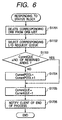
- Fig. 6 shows a processing procedure when the status block is received from the target.
- the corresponding ORB is deleted from the ORB list (step S1701).
- the I/O request queue in which the command for the corresponding ORB has been queued is selected (step S1702).
- the count value of the Current-QUE counter showing the number of commands (in the current ORB list) belonging to the selected I/O request queue is equal to or less than the number of reserved areas in the prefetch pool allocated to the I/O request queue or not is discriminated (step S1703). If the count value is equal to or less than the number of reserved areas, step S1704 follows. If it is larger than the number of reserved areas, step S1705 follows.
- step S1704 the count value of the Current-POOL counter for the prefetch pool is increased by 1.
- step S1705 subsequently, the count value of the Current-QUE counter showing the number of commands (in the current ORB list) belonging to the selected I/O request queue is decreased by 1.
- step S1706 the end of process is notified to the client corresponding to the selected I/O request queue. The client receives this notice and executes the processes of Fig. 4.
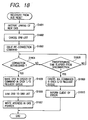
- a linking process of the new ORB is intermitted (step S1801) and the ORB list is cancelled (step S1802).
- a re-connection command of the SBP-2 connection is issued (step S1803) and whether the connection has been established or not is discriminated (step S1804).
- the connection is established again, the corresponding ORB is sequentially formed from the command at the head in each I/O request queue (step S1805). In this instance, the same ID as that assigned to the command before the bus reset is given to the "Seq_ID" field of each ORB.
- the formed ORB is linked to the ORB list (step S1806).
- the address is written into the ORB pointer (step S1807), thereby notifying the target of the generation of the ORB.
- step S1810 When a predetermined time elapses in a state where the connection cannot be established again (step S1808), all of the commands in each I/O request queue are cancelled (step S1809) and an error is informed to the client (step S1810).
- the processing routine is terminated.
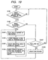
- Figs. 19 and 20 show processing procedures by the target which received the ORB.
- One fetch agent is prepared for one SBP-2 connection.
- the fetch agent fetches the ORB when the writing operation is performed to the doorbell register or ORB pointer.
- the apparatus waits until the writing operation is performed to the doorbell register or ORB pointer (step S1901).
- a check is made to see if the apparatus has been activated by the writing to the doorbell register (step S1902). If the apparatus is activated by the writing to the ORB pointer instead of the writing to the doorbell register, step S1903 follows. If the writing is performed to the doorbell register, a test is made to see if a "Next_ORB" field of the ORB designated by the ORB pointer is NULL (there is no subsequent ORB) (step S1907). If it is NULL, the processing routine is returned to step S1901.
- step S1908 follows and the value in the "Next_ORB" field of the ORB designated by the current ORB pointer is written into the ORB pointer and updated (step S1908).
- the processing routine advances to step S1903.
- the ORB is read out from the address (step S1903).
- the pointer indicating the free area in the prefetch pool is taken out from the free reference list and the read-out command ORB is stored into the free area (step S1905).
- the reference queue in which the command should be queued is selected with reference to the "QueueID" field of the ORB (step S1905).
- the pointer extracted from the free reference list is queued to the end of the selected reference queue (step S1906).
- the "Next_ORB" field of the ORB in which the queueing process is terminated is referred to and if its contents indicate NULL, namely, if there is not the linked ORB, the processing routine is returned to step S1901, the next ORB is linked, and the apparatus waits until the writing operation is performed to the doorbell register or ORB pointer. If there is the linked ORB, the value in the "Next_ORB" field of the ORB designated by the ORB pointer is written into the ORB pointer and updated (step S1908).
- the ORBs linked in the ORB list are sequentially stored into the prefetch pool.
- steps S1904 to S1906 are the same as those described as an ORB dispatcher in Fig. 1.
- Fig. 20 shows a procedure of the execution agent for each reference queue. Those procedures can be performed independently by a thread schedule by one thread in each reference queue. Or, all of the reference queues can be executed in a single thread by independently scheduling them in a manner such that the management of one reference queue is not blocked by the operations of the other reference queues. Or, a combination of those methods can be also used.
- Fig. 20 shows a procedure of the execution agent for one reference queue. The procedure of the execution agent for each reference queue is performed every reference queue.
- the execution agent first discriminates whether the pointer to the command in the prefetch pool exists in the reference queue or not (step S2001).
- the ORB is extracted from the prefetch pool (step S2002). The above processes are performed by using the pointer indicative of the head of the reference queue.
- SequenceIdentifier and Seq_ID of the ORB are set to the same digit number and Seq_ID is also added by 1 at a time. Therefore, when the process is progressing without a trouble, SequenceIdentifier and Seq_ID of the ORB ought to coincide in step S2003. Therefore, when the process normally progresses, the processing routine is shifted from step S2003 to step S2004.
- step S2004 Whether the buffer is ready in the client or not is discriminated. If it is ready, the data of a predetermined size from the address in which the value of data_descriptor of the ORB and an offset value stored in NextexecPointer held in the execution agent are added is accessed. The data is transmitted and received to/from the buffer prepared by the client (step S2005).
- a status block to notify of the completion of the processes is formed (step S2010) and written into the status FIFO (step S2011).
- the end of the process is notified to the client of the target (step S2012).
- the pointer in the reference queue indicative of the relevant command is returned to the free reference list.
- Seq_ID of the ORB is smaller than SequenceIdentifier in step S2003 corresponds to the case such that the initiator reproduces the ORB list by the procedure of Fig. 18 due to the bus reset or the like.
- the initiator even if the target terminated the processes and the value of SequenceIdentifier was also updated, when the bus reset occurs at a point when its status block does not reach the initiator, the initiator also includes the ORB into the ORB list.
- the value of SequenceIdentifier of the execution agent is larger than Seq_ID of the ORB.
- the status block is sent to the initiator in step S2010 and subsequent steps.
- Fig. 16 shows a processing procedure for an opening request from the client on the initiator side.
- a check is first made to see if the SBP-2 connection (login state) with the target of the connection destination has already been established (step S2501). If the SBP-2 connection has already been established, step S2507 follows. If the SBP-2 connection is not established yet, a login request (SBP-2 connecting request) is issued to the target (step S2502). Whether the login has succeeded or not is discriminated (step S2503). When the login fails, step S2513 follows, an error code is set to a return value, and the processing routine is returned.
- SBP-2 connection login state
- step S2504 When the login succeeds, an I/O request queue in which QueueID is equal to 0 is formed and a query command is issued thereto (step S2504). Subsequently, whether the query command has succeeded or not is discriminated (step S2505). If it fails, step S2512 follows and a logout is executed. After that, step S2513 follows. If the query command succeeds, the Current-POOL counter is set on the basis of "Init_POOL" of the status block for the query command.
- one or more areas are set as reserved areas of the I/O request queue in which QueueID corresponds to 0 and the remaining areas are set into the Current-POOL counter (step S2506).
- step S2507 follows and a desired ServiceID and Mode are designated for the I/O request queue in which QueueID corresponds to 0 and the connection command is queued (step S2507).
- "i" bit is set to 1 in case of obtaining an increase amount of the prefetch pool for the target. Whether the connection command has succeeded or not is discriminated (step S2508). If it fails, a check is made in step S2511 to see if another I/O request queue except for the queue corresponding to QueueID0 which is tacitly prepared is already present. If it is absent, a logout from the target is performed, namely, SBP-2 is disconnected (step S2512) and step S2513 follows.
- step S2513 follows without performing the logout.
- a new I/O request queue is formed in correspondence to QueueID1 and QueueID2 of the status block.
- a handle for allowing the client to specify this connection is made correspond.
- One or more reserved areas are set for each queue on the basis of the sum of the value in a Pool_Inc field of the status block and the value in the current Current-POOL register and the value in the Current-POOL register is updated by the number of remaining areas (step S2509).
- a handle which was made correspond to the I/O request queue formed finally is set to the return value (step S2510) and returned to the client on the calling source side.
- Fig. 17 shows a processing procedure on the target side corresponding to the processing procedure for the opening request from the client on the initiator side in Fig. 16.
- the target first waits for the arrival of a login request (step S2601).
- the target When the login request is received, the target performs a confirmation of the ID of the initiator, a formation of a login descriptor, and the like as operations specified in SBP-2.
- the target also forms a prefetch pool having at least one entry and forms a free reference list as a list of the pointers for the entries in the prefetch pool.
- a pointer for the reference queue in which QueueID is equal to 0 and the like are also prepared (step S2602).
- the target After completion of the above preparation, the target returns a login response specified in SBP-2 to the initiator (step S2603). Subsequently, the target waits for the arrival of the query command (step S2604).
- a size of formed prefetch pool is added into the "Init_POOL" field and a status block in response to the query command is sent (step S2605).
- the preparation for the communication by SHPT-2 can be made in this manner.
- a loop in step S2610 and subsequent steps relates to a processing procedure of the execution agent based on the reference queue of QueueID0. Whether the command is the connection command or not is discriminated in step S2606. If it is not the connection command, the processes of other commands are performed in step S2609. The processing routine is returned to step S2610. If it is the connection command, pointers for one or two reference queues or the like are formed in accordance with the mode designated in the Mode field. At this time, if "i" bit of the connection command is equal to 1, entries of the number that is equal to or larger than the number of formed reference queues are added into the prefetch queue (step S2607). The IDs of the formed reference queues and the number of entries added into the prefetch queue are returned to the initiator by the status block for the connection command (step S2608). The communication between the clients can be performed by using the reference queues formed after that.
- a request queue can be formed in the initiator, a reference queue can be formed in the target, and a path is set between them.
- the procedures of Figs. 16 and 17 are also used upon setting of a management path (a pair of management request queue and management reference queue) which is formed at the time of login.
- Fig. 21 shows a processing procedure for a closing request from the client on the initiator side.
- a disconnection command is first issued.
- the "QueueID" field of the disconnection command is set to relevant QueueID0.
- the disconnection command is issued to QueueID.
- a queue to be disconnected is designated in the "QueueID1" and "QueueID2" fields (step S2701).
- the apparatus subsequently waits for completion of the disconnection command (step S2702).
- Fig. 22 shows a disconnection processing procedure of the target. This procedure is located in step S2609 in Fig. 17.
- step S2804 the status block in response to the disconnection command is returned (step S2804).
- all of the un-processed pointers remaining in the reference queue are returned to the free reference list (step S2805). If the prefetch pool was increased upon connection, the added amount is decreased and the pointers in the free reference list which is referred to are deleted by the decreased amount. Further, the pointers or the like for the reference queues are also deleted (step S2806). The processing routine is returned.
- a field of a queue identifier such as QueueID is provided for the ORB. Therefore, the SHPT-2 processor and ORB dispatcher identify the queue identifier and each of them independently executes the process, namely, performs the formation and process of the ORB every queue, so that a multiconnection (channel) by a plurality of queues can be realized. In this case, even in one piece of equipment, an asynchronous communication can be performed every client by allocating one connection (channel) to each of a plurality of clients included there.
- the hybrid apparatus can be used by the host computer connected thereto as if each function were independent equipment.
- the multiconnection since the management of each queue and the execution agent are logically independent processes, the multiconnection (channel) can be easily realized.
- a data exchange can be performed bidirectionally between the initiator and the target by a simple control procedure. That is, the initiator can send desired data to the target anytime.
- the target can read out the data sent from the initiator in accordance with circumstances of the target itself. So long as the initiator is prepared, the target can send data to the initiator any time irrespective of a spontaneous purpose or a request from the initiator. Even if the bus reset occurs, the continuation of the processes from the intermitted state just before the bus reset can be guaranteed.
- the initiator dynamically performs the allocation of the whole command pool area of the target on the multiplex path by the queue, so that communicating efficiency and resource using efficiency of the target are improved. Since the command pool area of the target is increased or decreased in accordance with the number of queues which are used for connection, the resource using efficiency of the target is improved.
- the multichannels can be provided between the client of the initiator and the client of the target by SHPT-2.
- SHPT-2 a command in the path in which the process is connected to the initiator is not processed. Therefore, in the case where the issued commands including the command that is being processed are cancelled in a lump for the stopped process or the like, the command is blocked by the ORB which was issued precedently, the cancel command does not reach the process of the target, and the commands cannot be cancelled on a path unit basis.
- a printer is now presumed as a target.
- the rendering process also has to be stopped.
- the cancel command is linked after the write command which has been issued precedently and is used for allowing the printer to print, so that the cancel command cannot be issued for the rendering process.
- the management queue is used and a KILL command to extinguish such a queue for the target is prepared. Since SHPT-2 operates on SBP-2, it is necessary to perform a process of the KILL command in accordance with the rule of SBP-2. Therefore, the initiator and the target mainly operate as follows with regard to the KILL command.
- the ORB of the KILL command has the same format as that of the disconnect ORB shown in Fig. 11. That is, the ID of the management queue is set into the "QueueID” field. The ID of the queue to be extinguished is set into the "QueueID1" and “QueueID2" fields. A predetermined code corresponding to the KILL command is set into the "Function" field.
- the status block for the KILL command is similar to that shown in Fig. 13.
- the status for the command aborted by the KILL command is "Aborted".
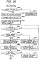
- Figs. 26 and 27 show the operation of the queue management agent to manage each I/O request queue of the initiator.
- Fig. 28 shows the operation of the manager of the SBP-2 layer.
- Fig. 28 describes processes which are executed in the SBP-2 layer.
- Fig. 29 shows processes which are executed by the execution agent of the target.
- Fig. 30 shows processes which are executed by the fetch agent to fetch the command from the reference queue.
- Figs. 26 and 27 show a processing procedure when the queue management agent of a certain I/O request queue receives some request from an upper client. However, an explanation of the requests other than the cancel request is omitted here.
- the cancel request is issued when the user cancels a certain job. For example, when the print job is cancelled or the like, the cancel request of the queue corresponding to the print job is issued from the client.
- step S2601 whether the request from the client is the cancel request or not is discriminated. In case of a request other than the cancel request, the process according to it is executed (step S2614).
- the request regarding the queue is no longer accepted (step S2602).
- the internal status is set to "killing” (the KILL command is being processed) (step S2603). It is also possible to construct in a manner such that if the internal status is "killing", the subsequent requests are not accepted. After that, the transmission of the "KILL command (kill queue command)" is requested to the queue management agent of the management queue 203f (step S2604).
- the apparatus waits for reception of the status block in step S2605.
- the status block is received, the contents of the received status are discriminated (step S2606).
- the status for the command which has already been connected to the queue to be killed is "aborted” or "queueID error”. Therefore, if the status is normally terminated, it is determined that this status is a response of the normal termination for the command issued before the KILL command.
- the command corresponding to the status block received from the I/O request queue (command queue) is deleted (step S2615).
- the normal termination is reported to the upper client (step S2616). After that, the apparatus waits for the status block responsive to the KILL command.
- step S2607 If the received status block is not normally terminated, it is decided that this status is a response to the KILL command.
- the command corresponding to the status is deleted from the I/O request queue (step S2607).
- a message indicating that the status block is not normally terminated (it was aborted) is informed to the upper client (step S2608).
- step S2610 determines whether the internal status is "killing" or not. This is because the processes in steps S2605 to S2609 and steps S2615 and S2616 can be shared in common with the other processes such as a process "AbortTaskSet", which will be explained hereinlater, and the like.
- step S2611 When the internal status is "killing", whether the command in which the status block is not received yet has been queued in the I/O request queue (command queue) or not is discriminated (step S2611). If there is no command, all of the resources occupied by the queue extinguished by the KILL command are released (step S2612). The management agent itself of the extinguished queue is extinguished (step S2613).
- this command is deleted from the queue (step S2618).
- a message indicating that the command was deleted without being executed is notified to the upper client (step S2619).
- Fig. 28 shows processes by the manager of the SBP-2 layer locating under the SHPT-2 layer.
- a queueID error showing the absence of the queue of the destination is returned as a response of the SBP-2 layer from the fetch agent in response to the command which ought to be processed by the execution agent.
- Fig. 28 shows a procedure for processing it.
- the apparatus waits for the reception of the status block (step S2801). Although a similar process is executed even in the diagrams other than Fig. 28, it is assumed that the process for waiting the status black or the like is waited in a loop in the embodiment. However, it is also possible to once terminate the task at a point when the apparatus enters a waiting state and resume it by an interruption of the status reception.
- step S2802 When the status is received, whether the status block is a queueID error or not is discriminated (step S2802). If it is not the queueID error, the process according to this status is performed (step S2806). If it is the queueID error, since this queue does not exist, the memory resource of the corresponding ORB is released (step S2803). Whether the issuing source of the deleted and released ORB, namely, the queue management agent of the SHPT layer corresponding to the queueID error status is not extinguished (it is active) yet or not is discriminated (step S2804). If it is not active, since this means that a partner to which the queueID error is reported is absent, nothing is performed and the apparatus waits for the status block again (step S2805).
- the queueID error is reported to the agent (step S2807).
- the execution agent of each reference queue which received the notice of the KILL command from the execution agent of the management queue operates as shown in Fig. 29.
- the notice of the KILL command is accepted by the interruption.
- step S2901 whether the notice is the notice of the KILL command is discriminated (step S2901). If NO, the process according to an interrupt event is executed (step S2909). If it is the notice of the KILL command, the command which is being executed at present is immediately aborted (step S2902).
- step S2903 a check is made to see if there is a command in which the status block is unsaved although the execution has been completed. If YES, the status block for the command is saved and returned to the initiator (step S2910).
- step S2904 the status of "Aborted” is informed to the command aborted during the process.
- the ORB of the aborted command is released by a normal procedure (step S2905).
- a message (“dead") indicative of the extinction of the execution agent is notified to the fetch agent (step S2906).
- the resource occupied by the execution agent is released (step S2907).
- the execution agent itself is extinguished (step S2908).
- the queue and command in the target and the agent itself are extinguished and the "Aborted" status is returned, thereby notifying the initiator of a point that a series of processes regarding the KILL command is executed.
- the fetch agent which received the notice of "dead” in step S2906 in Fig. 29 operates in accordance with a procedure of Fig. 30.
- step S3001 whether the interrupt event is the "dead” notice from the execution agent or not is discriminated and, if NO, the process corresponding to the interrupt event is performed (step S3001). If it is not the "dead” notice, the queueID (agent queueID) corresponding to the agent which sent the "dead” notice is deleted from an active queue list as a list of the active agents possessed by the fetch agent (step S3002). After that, a check is made to see if the command belonging to the agent queueID, namely, the ORB having the deleted queueID is included in the ORB list (step S3003). If YES, with respect to this ORB, the queueID error status is saved in the status block and returned to the initiator (step S3006). If it is not included, all of the resources reserved by the fetch agent for the queue which sent the "dead” notice are released (step S3004).
- the “AbortTaskSet” process is not the command defined in SHPT-2 but a command defined in SBP-2.
- This command is issued and executed to eliminate the mismatching.
- the target receives the AbortTaskSet command in the management register.
- the management execution agent notifies the execution agent in each queue so as to immediately abort the execution.
- Each execution agent which received the notice of the abortion of the execution instantaneously aborts the execution. If there is any ORB in which the status block of the execution completion is not saved although the execution has been completed, the status block of the execution completion is saved to this ORB.
- SeqID is an identifier assigned to the command
- “residual” is a pointer indicative of the unprocessed area of the data linked to the command. They are held in the target while being updated successively during the process of the command.
- the "SeqID” and “residual” are saved into areas (called SeqID and residual upon abortion) different from the areas (called current SeqID and residual) for the command which is being processed. That is, a data area of the data that is unprocessed due to the abortion is stored.
- the status block having the aborted status is saved to the aborted command (ORB).
- the agent of the queue of SHPT in the initiator understands that the AbortTaskSet was issued.
- the SBP-2 layer cancels all of the unprocessed ORBs belonging to such a queue are cancelled.
- the SHPT layer reports the cancellation to the upper layer.
- the upper layer maintains the contents in the memory buffer associated with the ORB corresponding to the status having the Aborted status and the memory buffer associated with the subsequent commands and requests the SHPT layer to resume.
- the SHPT layer assigns the same SeqID as the command of the ORB corresponding to the status block having the received Aborted status to a parameter for a resuming request and requests the SBP-2 layer to form and issue an ORB.
- the SHPT layer assigns SeqID+1 of the command corresponding to the status block having the received Aborted status to the new command and requests the SBP-2 layer to form an ORB.
- the execution agent of the relevant queue which received the ORB (command) for the first time after completion of the AbortTaskSet command refers to SeqID of the received command.
- SeqID is the same as the current SeqID as a result of the reference, the execution agent understands that it is a new command, and executes the command from the beginning. All of the contents of SeqID and residual upon abortion are cleared at a point when the first data transmission is terminated normally.
- SeqID is different from the current SeqID as a result of the reference, it is compared with the SeqID upon abortion. If it is identical to the current SeqID, the execution agent understands that the aborted command is resumed, copies the contents of the SeqID and residual upon abortion to the current SeqID and residual, and resumes the execution in accordance with the copied contents.
- the target receives the AbortTaskSet command into the management register.
- the management execution agent notifies the execution agent in each queue so as to immediately abort the execution.
- Each execution agent which received the notice to abort the execution immediately aborts the execution. If there is any ORB in which the status block of the execution completion is not saved although the execution has already been completed, the status block of the execution completion is saved into this ORB.
- SeqID of the aborted command is saved into the SeqID at the aborted time point, and the number of unexecuted bytes of the command is saved into residual at that time point.
- SeqID+1 of the command whose execution was aborted is written into the current SeqID.
- "Null" no byte is executed
- the status block having the Aborted status is saved into the aborted command (ORB).
- the agent of the queue of SHPT in the initiator understands that the AbortTaskSet command was issued.
- the SHPT layer forms a command having a buffer of the same parameter, same SeqID, and same contents as those of the command of the ORB corresponding to the status block having the received Aborted status, and requests the SBP-2 layer to form and issue an ORB.
- the execution agent of the relevant queue which received the ORB (command) for the first time after completion of the execution of the AbortTaskSet command refers to the SeqID of the received command.
- SeqID SeqID
- residual upon abortion are cleared at a point when the first data transmission is normally terminated.
- SeqID differs from the current SeqID as a result of the reference, it is compared with the SeqID upon abortion. If it is identical to the current SeqID, the execution agent understands that the aborted command is resumed, copies the contents of the SeqID and residual upon abortion to the current SeqID and residual, and resumes the execution in accordance with the copied contents.
- the command can be executed continuously or a new command can be processed in accordance with a will of the upper client.
- the AbortTaskSet command can be processed without influencing the upper client of the SHPT layer.
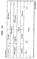
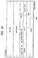
- Fig. 36 shows a format of the management ORB of the AbortTaskSet command.
- the kind of command is shown by the "function" field.
- An address in an FIFO to return the status is designated by a "status_FIFO” field of the command.
- This command is executed by the management execution agent (not shown in Fig. 1).
- Fig. 37 shows a format of the status block for the AbortTaskSet command.
- the issuer of the AbortTaskSet command can discriminate whether this command has been processed normally or not by referring to this status.
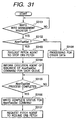
- Fig. 31 shows a processing procedure by the management register execution agent when data is written into a management register existing in the target.
- Figs. 32 and 33 show processes in the execution agent with respect to each queue of the target.
- Fig. 34 shows a processing procedure when the queue management agent of the initiator receives the status block.
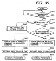
- Fig. 35 likewise shows a processing procedure when the queue management agent receives a transmission request from the upper client.
- the management register exists in the target as shown in Fig. 1 and can write some data from the initiator. This writing operation is performed to send the command for managing the SBP-2 layer to the target. For example, the AbortTaskSet command is written in the case where an error of the SBP-2 layer, for example, an error of the queueID, a time-out of a retry, an error report from the upper client, or the like is found out by the client process or the like.
- Fig. 31 shows a procedure for performing the process according to a value which is written in the management register when it is written therein.
- step S3101 the apparatus first waits until a command is written into the management register.
- the writing operation can be also performed by using the interruption as a trigger.
- a command is written, whether its contents indicate the AbortTaskSet command or not is discriminated (step S3102). If NO, a process corresponding to the contents is performed but its description is omitted here (step S3108). If YES, the fetching of the ORB by the fetch agent is stopped (step S3103). A message showing that the AbortTaskSet command was issued to the execution agent with respect to all of the queues is informed (step S3104). The execution agent performs processes, which will be explained hereinlater, on the basis of this notice. The completion of the process for the AbortTaskSet command is reported to the management register execution agent. In step S3105, the apparatus waits for the arrival of the completion notices from all of the execution agent.
- Figs. 32 and 33 show a processing procedure by each execution agent which receives the notice in step S3104 in Fig. 31.
- step S3201 whether the a notice indicative of the reception of the AbortTaskSet command has arrived or not is discriminated. If NO, the normal process is performed (step S3221). If YES, the process which is being executed at present is aborted immediately.
- the processing routine of Fig. 32 can be started from step S3202 by an interruption.
- the SeqID of the aborted command is saved as SeqID upon abortion every execution agent (step S3203).
- the address in the data buffer which is unprocessed due to the abortion, namely, the current residual is saved as a residual upon abortion (step S3204).
- step S3205 A check is made to see if there is any command in which the status block of the completion notice is not saved after the abortion of the command process in spite of a fact that is has already been completed, namely, command (ORB) which does not send a response showing the completion to the initiator (step S3205). If YES, the status block of the completion is saved with respect to all of those commands (step S3222).
- the status block to wait for the Aborted status is saved for the command whose execution was aborted and the apparatus responds to the initiator (step S3206). All of the ORBs and commands belonging to the execution agent are cancelled (step S3207).
- the SeqID of the aborted command is saved as a current SeqID (step S3208). "NULL" is saved as a current residual (step S3209).
- the processes for AbortTaskSet are terminated in this manner and a preparation for processing a new command is completed. Therefore, the completion of the process of AbortTaskSet is informed to the management register execution agent (step S3210).
- step S3211 the apparatus waits until the fetch agent activated in step S3107 in Fig. 31 fetches a new ORB.
- the process can be also started by the interruption after the fetching.
- step S3212 When the new ORB is fetched, whether the SeqID of the fetched command (ORB) is equal to the current SeqID set in step S3208 or not is discriminated (step S3212). When it is determined that they are not equal, whether the SeqID of the fetched command is equal to the value saved as SeqID upon abortion in step S3203 or not is discriminated (step S3213). If the SeqID of the fetched command is none of the above values, since this means that the incorrect SeqID has been assigned to the command, an error process is performed (step S3227).
- SeqID of the fetched command is equal to the value saved as SeqID upon abortion in step S3203, it is understood that the command is a request to resume the aborted command, and the value saved as SeqID upon abortion in step S3203 is copied as a current SeqID (steps S3214 and S3215). Similarly, the residual upon abortion saved in step S3204 is copied as a current residual (step S3216). The unnecessary SeqID and residual upon abortion are invalidated (steps S3217 and S3218).
- step S3219 The execution of the command is resumed in accordance with the current SeqID and residual set in steps S3215 and S3216 (step S3219). After that, the processing routine is returned to the normal process (step S3220).
- step S3212 When it is determined in step S3212 that the SeqID of the fetched command (ORB) is equal to the current SeqID set in step S3208, it is understood that the command is a new command, and the unnecessary SeqID and residual upon abortion are invalidated (steps S3223 to S3225).
- the new fetched command is executed (step S3226). The processing routine is returned to the normal process.
- the command is a command to resume after the abortion or a new command is discriminated by the value of SeqID assigned to the command. In accordance with the discrimination result, if it is the command to resume, the process is executed continuously. If it is the new command, this command is newly executed.
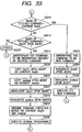
- Fig. 34 shows a processing procedure by each queue management agent to manage each I/O request queue of the initiator.
- step S3401 When the status block is received, whether the Aborted status exists in the received status block or not is discriminated (step S3401). If NO, the normal process is performed (step S3408). If YES, whether the KILL command has been issued or not is discriminated (step S3402). It is sufficient to perform this discrimination with reference to the internal status set in step S2603 in Fig. 26. If the KILL command was issued, the process of the KILL command shown in Figs. 26 and 27 is executed (step S3409).
- step S3403 and S3404 If the KILL command is not issued, it is understood that there is a response to the AbortTaskSet command, and whether an error has occurred in the queue regarding the queue management agent which executes the relevant process or not is discriminated (steps S3403 and S3404). Various contents of the generated error are considered. For example, there are an error of the queueID, a time-out of the retry, an error state notified from the upper client, and the like.
- the SHPT of the same queue after the aborted command requests the SBP-2 to issue the ORBs for all of the commands which received the request from the upper client (step S3407). That is, the issue of the ORB is requested again to the SBP-2 with respect to all of the commands linked to the request queue as a target of the management of the agent to execute the current process.
- step S3404 When it is decided in step S3404 that the error occurred, all of the commands regarding the queue having an error are cancelled. Therefore, the aborted command is informed to the upper client (step S3410) and an aborted flag (Aborted FLG) is turned on (step S3411). All of the commands queued after the aborted command are erased and a message showing that the erased commands were cancelled is informed to the client (step S3412).
- Fig. 35 shows a procedure when the queue management agent receives a request from the upper client.
- the apparatus waits for the transmission request from the upper client (step S3501).
- the aborted flag (Aborted FLG) is tested (step S3502).
- the queue management manager which received the status block of Aborted status determines that there is an error in the queue as a management target
- the Aborted FLG is set in step S3411 in Fig. 34. If this flag is not ON, since this transmission request is a normal request, the command is processed in the normal manner (step S3507).
- this flag When this flag is ON, whether the transmission request indicates the re-transmission of the aborted transmission request or a new transmission request is discriminated. As a standard in this discrimination, for example, it is sufficient to provide a flag for re-transmission or the like every queue and discriminate by the ON/OFF state of such a flag.
- the same SeqID as that of the aborted command is assigned to the command in which the re-transmission was requested (step S3504) and the issue of the ORB is requested to the SBP-2 layer (step S3505). After that, the processing routine is returned to the normal process. When the process is terminated, the apparatus waits for the arrival of the transmission request (step S3506).
- the SeqID that is larger than that of the aborted command by 1 is assigned to the command to be transmitted (step S3508) and the issue of the ORB is requested to the SBP-2 layer (step S3509). After that, the normal process is executed (step S3510).
- Fig. 38 shows an example of a state after the AbortTaskSet process when there is no error with regard to a write I/O request queue.
- Commands W2 and W3 (a numeral denotes SeqID) included in the queue upon issuing of the AbortTaskSet command have been queued as they are in a write I/O request queue 3802 of an initiator 3801.
- the AbortTaskSet is issued during the W2 process, the SeqID of W2 is equal to 2, and the value of residual upon abortion is equal to 4000. Those values are held as a saving value 3806 upon abortion.
- Fig. 39 shows a state when the process is started from a new command without continuing the aborted command with respect to the queue with an error.
- the queue since the queue has the error, all of the contents in the write I/O queue 3802 in addition to those in the ORB list 3807 and those in the write queue 3804 of the target are once cancelled.
- the ORB to which the next value "3" of SeqID upon abortion has been assigned is newly issued. Since this SeqID coincides with a current SeqID 3805, the command W3 is executed from the beginning. This state is shown in Fig. 39.
- a set of a desired request queue and its management agent and a set of the corresponding reference queue and the execution agent, namely, desired paths can be extinguished at a desired timing by the KILL command using the management queue. Therefore, even if the process of the command in the path to be extinguished is aborted due to some causes, the path can be extinguished immediately. Since no influence is exercised on the paths other than the path to be extinguished, not only the formation and the extinction for every channel linked between the client processes, but also the abortion and extinction of the process can be realized every command of the contents with respect to the channel in which the command which is being processed remains.
- the process can be returned to the state before execution of the AbortTaskSet command without participation by the client process.
- the aborted command can be continued or the process can be resumed from a new command in dependence on the client process.
- the invention can be applied to a system constructed by a plurality of equipment (for example, a host computer, interface equipment, a reader, a printer, and the like) or can be also applied to an apparatus (for example, a copying apparatus, a facsimile apparatus, or the like) comprising one piece of equipment.
- equipment for example, a host computer, interface equipment, a reader, a printer, and the like
- apparatus for example, a copying apparatus, a facsimile apparatus, or the like
- the object of the invention is also accomplished by a method whereby a storage medium in which program codes of the procedures shown in Figs. 3 to 6, 16, 18, 21, 26 to 28, 34, and 35 have been recorded is supplied to a computer and the computer (or a CPU or an MPU) reads out and executes the program codes stored in the storage medium.
- the object of the invention can be also accomplished by a method whereby a storage medium in which program codes of the procedures shown in Figs. 17, 19, 20, 22, and 29 to 33 have been recorded is supplied to a computer and the computer (or a CPU or an MPU) reads out and executes the program codes stored in the storage medium.
- a storage medium to supply the program codes for example, a floppy disk, a hard disk, an optical disk, a magnetooptic disk, a CD-ROM, a CD-R, a magnetic tape, a non-volatile memory card, an ROM, or the like can be used.
- the invention incorporates not only a case where the functions of the embodiment mentioned above are realized by executing the read-out program codes by a computer but also a case where the functions of the embodiment mentioned above are realized by a method whereby the OS (Operating System) or the like which operates on the computer executes a part or all of the actual processes on the basis of instructions of the program codes and the functions of the embodiment mentioned above are realized by those processes.
- OS Operating System
- the invention also incorporates a case where the program codes read out from the storage medium are written into a memory equipped for a function expanding board inserted into the computer or a function expanding unit connected to the computer and, after that, a CPU or the like equipped for the function expanding board or function expanding unit executes a part or all of the actual processes on the basis of instructions of the program codes, and the functions of the embodiment mentioned above are realized by those processes.
- a main apparatus serving as an initiator by executing the program codes read out from the storage medium is not limited to the computer but any data transmission equipment can be used so long as it has a login ability of SBP-2.
- pipeline processes can be realized by using a plurality of reference queues, for example, by storing a print job into a first reference queue, storing a read command to confirm a status of the target into a second queue, and storing a finisher control command into a third queue, and after completion of the printing based on a print job, a next print job can be stored into the first reference queue prior to terminating the execution of the function by the finisher.
- the initiator can instruct the decrease amount upon disconnection.
- a "POOL_Dec" field 309f is provided and an amount of prefetch pool to be released to the target is designated in this field when the initiator issues the disconnection command as shown in Fig. 23.
- the command is issued in step S2701 in Fig. 21.
- the target decreases the prefetch pool by the amount designated by the "POOL_Dec" field in step S2806 in Fig. 22.
- the SHPT-2 processor and ORB dispatcher identify the queue identifier and each of them independently executes the process, namely, performs the formation and process of the ORB every queue, so that a multiconnection (channel) by a plurality of queues can be realized.
- an asynchronous communication can be performed every client by allocating one connection (channel) to each of a plurality of clients included therein.
- the hybrid apparatus can be used by the host computer connected thereto as if each function were independent equipment.
- the multiconnection since the management of each queue and the execution agent are logically independent processes, the multiconnection (channel) can be easily realized.
- a data exchange can be performed bidirectionally between the initiator and the target by a simple control procedure. That is, the initiator can send desired data to the target anytime.
- the target can read out the data sent from the initiator in accordance with circumstances of the target itself. So long as the initiator is prepared, the target can send data to the initiator any time irrespective of a spontaneous purpose or a request from the initiator. Even if the bus reset occurs, the continuation of the processes from the intermitted state just before the bus reset can be guaranteed.
- the initiator dynamically performs the allocation of the whole command pool area of the target on the multiplex path by the queue, so that communicating efficiency and resource using efficiency of the target are improved. Since the command pool area of the target is increased or decreased in accordance with the number of queues which are used for connection, the resource using efficiency of the target is improved.
- the initiator can also request the increase by designating the increase number. In this case, it is sufficient to increase the number of bits in the "i" field in the connection command in Fig. 10 and indicate the increase number.
- the first embodiment has been constructed in a manner such that the reserved areas corresponding to the prefetch pool for the queue on the initiator side are set only at the time of the connection, the reserved areas can be also increased or decreased anytime other than the time of the connection.
- the increased amount of the reserved areas is set so as not to exceed the value in the Current-POOL counter, the number of reserved areas is increased and the count value in the Current-POOL counter is decreased within such a range.
- the count value can be decreased in a range such that a difference between the number of ORBs and the number of reserved areas is set to an upper limit and a range in which the number of reserved areas after the reduction is equal to or larger than 1 in such a range. In this case, the number of reserved areas is reduced within such a range and the count value in the Current-POOL counter is increased.
- the SHPT-2 processor and ORB dispatcher identify the queue identifier and each of them independently executes the process, namely, performs the formation and process of the ORB every queue, so that a multiconnection (channel) by a plurality of queues can be realized.
- an asynchronous communication can be performed every client by allocating one connection (channel) to each of a plurality of clients included there.
- the hybrid apparatus can be used by the host computer connected thereto as if each function were independent equipment.
- the multiconnection since the management of each queue and the execution agent are logically,independent processes, the multiconnection (channel) can be easily realized.
- a data exchange can be performed bidirectionally between the initiator and the target by a simple control procedure. That is, the initiator can send desired data to the target at any time.
- the target can read out the data sent from the initiator in accordance with circumstances of the target itself. So long as the initiator is prepared, the target can send data to the initiator any time irrespective of a spontaneous purpose or a request from the initiator. Even if the bus reset occurs, the continuation of the processes from the intermitted state just before the bus reset can be guaranteed.
- the initiator dynamically performs the allocation of the whole command pool area of the target on the multiplex path by the queue, so that communicating efficiency and resource using efficiency of the target are improved. Since the command pool area of the target is increased or decreased in accordance with the number of queues which are used for connection, the resource using efficiency of the target is improved.
- a "delta" field 309g shows a numerical value with a sign of a format of a complement of 2. If this field is positive, the increase in the prefetch pool is instructed to the target. If it is negative, the decrease in the prefetch pool is instructed to the target. The target actually increases or decreases the prefetch pool in response to the instruction of the command.
- the initiator issues a prefetch pool changing command, thereby increasing the prefetch pool. Since the target has already received the prefetch pool changing command separately if necessary before step S2607 in Fig. 17, only the pointers or the like for the reference queues are formed.
- the prefetch pool capacity changing command is issued, thereby reducing the prefetch pool. Since the prefetch pool capacity changing command ought to be issued from the initiator later, in the process (Fig. 22) of the disconnection command, only the pointers or the like which are used for the reference queues are deleted and the prefetch pool is not decreased in step S2806.
- the SHPT-2 processor and ORB dispatcher identify the queue identifier and each of them independently executes the process, namely, performs the formation and process of the ORB every queue, so that a multiconnection (channel) by a plurality of queues can be realized.
- an asynchronous communication can be performed every client by allocating one connection (channel) to each of a plurality of clients included there.
- the hybrid apparatus can be used by the host computer connected thereto as if each function were independent equipment.
- the multiconnection since the management of each queue and the execution agent are logically independent processes, the multiconnection (channel) can be easily realized.
- a data exchange can be performed bidirectionally between the initiator and the target by a simple control procedure. That is, the initiator can send desired data to the target at any time.
- the target can read out the data sent from the initiator in accordance with circumstances of the target itself. So long as the initiator is prepared, the target can send data to the initiator any time irrespective of a spontaneous purpose or a request from the initiator. Even if the bus reset occurs, the continuation of the processes from the intermitted state just before the bus reset can be guaranteed.
- the initiator dynamically performs the allocation of the whole command pool area of the target on the multiplex path by the queue, so that communicating efficiency and resource using efficiency of the target are improved. Since the command pool area of the target is increased or decreased in accordance with the number of queues which are used for connection, the resource using efficiency of the target is improved.
- an asynchronous bidirectional communication can be performed and its multichannel can be realized by one login between the initiator and the target and the resources such as processes and memory which are necessary for data exchange can be efficiently used.
- the target can read out the data in accordance with its circumstances and a situation such that the initiator is occupied by the data transmission due to the circumstances of the target can be prevented.
- the number of commands which can be transmitted from the initiator to the target is not managed every queue of the target but is unitarily managed, so that the resources can be efficiently used.
- the communicating efficiency and the resource using efficiency of the target are improved.
- the command pool areas of the target are increased or decreased in accordance with the number of queues which are used for connection.
- the resource using efficiency of the target can be improved.
- the set of a desired request queue and its management agent and the set of the corresponding reference queue and the execution agent, namely, desired paths can be extinguished at a desired timing irrespective of the state of the path.
- the process can be returned to the state before the execution of the AbortTaskSet command without anticipation by the client process.
- the queue (path) having an error although the contents are erased, the aborted command can be continued or the process can be resumed from a new command in accordance with the client process.
- an electrical signal carrying processor implementable instructions for controlling a processor to carry out the method as hereinbefore described.
Landscapes
- Engineering & Computer Science (AREA)
- General Engineering & Computer Science (AREA)
- Theoretical Computer Science (AREA)
- Computer Hardware Design (AREA)
- Computer Networks & Wireless Communication (AREA)
- Signal Processing (AREA)
- Physics & Mathematics (AREA)
- General Physics & Mathematics (AREA)
- Communication Control (AREA)
- Information Transfer Systems (AREA)
- Computer And Data Communications (AREA)
- Data Exchanges In Wide-Area Networks (AREA)
Claims (14)
- Procédé de commande de communication pour faire fonctionner un initiateur qui communique avec une cible par l'intermédiaire d'une pluralité de voies (202a-202d), comprenant :caractérisé en ce qu'il comprend en outre :une étape de transmission consistant à transmettre, par l'intermédiaire d'au moins l'une de la pluralité de voies, un ordre d'effacement d'une voie désignée différente de la, au moins une, voie vers la cible ; etune étape d'effacement consistant à effacer le côté de l'initiateur de la voie désignée lorsqu'une réponse signifiant l'effacement du côté de la cible de la voie désignée est reçue de la cible.
- Procédé selon la revendication 1, dans lequel, lorsque la réponse est reçue de la cible, ladite étape d'effacement efface un ordre qui a été transmis à la cible pour exécution, mais pour lequel la cible n'a pas été informée de l'achèvement de l'exécution, puis efface le côté de l'initiateur de la voie désignée.
- Procédé selon la revendication 1, comprenant en outre une étape de commande qui consiste à commander la cible de manière que :une communication utilisant la voie désignée soit abandonnée ;le côté de la cible de cette voie soit effacé ; etune réponse indiquant l'effacement soit envoyée à l'initiateur, en réponse à l'ordre d'effacement transmis dans ladite étape de transmission, ladite étape d'effacement effaçant le côté de l'initiateur de la voie désignée à la réception de la réponse.
- Procédé de commande de communication pour faire fonctionner une cible qui communique avec un initiateur par l'intermédiaire d'une pluralité de voies, comprenant :caractérisé en ce qu'il comprend en outre :une étape d'effacement qui, en réponse à un ordre d'effacement d'une voie désignée provenant de l'initiateur, abandonne une communication utilisant la voie désignée et efface le côté de la cible de cette voie ; etune étape d'envoi consistant à envoyer une réponse signifiant l'effacement du côté de la cible de la voie à l'initiateur afin de permettre à l'initiateur d'effacer le côté de l'initiateur de la voie désignée.
- Procédé selon la revendication 4, dans lequel, si un ordre qui a été reçu par l'intermédiaire de la voie désignée est en cours d'exécution, ladite étape d'effacement abandonne l'exécution de l'ordre.
- Procédé selon la revendication 4, dans lequel, lorsqu'un ordre est reçu depuis l'initiateur par l'intermédiaire de l'une de la pluralité de voies qui a été effacée dans la cible, ladite étape d'envoi envoie la réponse signifiant une destination incorrecte à l'initiateur.
- Initiateur destiné à communiquer avec une cible par l'intermédiaire d'une pluralité de voies, comportant :caractérisé en ce qu'il comporte en outre :un moyen de transmission destiné à transmettre, par l'intermédiaire d'au moins l'une de la pluralité de voies, un ordre d'effacement d'une voie désignée différente de la, au moins une, voie vers la cible ; etun moyen d'effacement destiné à effacer le côté de l'initiateur de la voie désignée lorsqu'une réponse signifiant l'effacement du côté de la cible de la voie désignée est reçue de la cible.
- Initiateur selon la revendication 7, dans lequel, lorsque la réponse est reçue de la cible, ledit moyen d'effacement efface un ordre qui a été transmis à la cible pour exécution, mais pour lequel la cible n'a pas été informée de l'achèvement de l'exécution, puis efface le côté de l'initiateur de la voie désignée.
- Initiateur selon la revendication 7, comportant en outre un moyen de commande destiné à commander la cible de manière que :une communication utilisant la voie désignée soit abandonnée ;le côté de la cible de cette voie soit effacé ; etune réponse indiquant l'effacement soit envoyée audit initiateur, en réponse à l'ordre d'effacement transmis par ledit moyen de transmission, ledit moyen d'effacement effaçant le côté de l'initiateur de la voie désignée à la réception de la réponse.
- Cible qui communique avec un initiateur par l'intermédiaire d'une pluralité de voies, comportant :caractérisée en ce qu'elle comporte en outre :un moyen d'effacement destiné, en réponse à un ordre d'effacement d'une voie désignée provenant de l'initiateur, à abandonner une communication utilisant la voie désignée et à effacer le côté de la cible de cette voie ; etun moyen d'envoi destiné à envoyer une réponse signifiant l'effacement du côté de la cible de la voie à l'initiateur afin de permettre à l'initiateur d'effacer le côté de l'initiateur de la voie désignée.
- Cible selon la revendication 10, dans laquelle, si un ordre qui a été reçu par l'intermédiaire de la voie désignée est en cours d'exécution, ledit moyen d'effacement abandonne l'exécution de l'ordre.
- Cible selon la revendication 10, dans laquelle, lorsqu'un ordre est reçu depuis l'initiateur par l'intermédiaire de l'une de la pluralité de voies qui a été effacée dans ladite cible, ledit moyen d'envoi envoie la réponse signifiant une destination incorrecte à l'initiateur.
- Programme d'ordinateur comprenant des instructions exécutables par un processeur pour commander un initiateur afin d'exécuter la totalité des étapes d'un procédé selon l'une quelconque des revendications 1 à 3.
- Programme d'ordinateur comprenant des instructions exécutables par un processeur pour commander une cible afin d'exécuter toutes les étapes d'un procédé selon l'une quelconque des revendications 4 à 6.
Applications Claiming Priority (2)
| Application Number | Priority Date | Filing Date | Title |
|---|---|---|---|
| JP35362798A JP3990833B2 (ja) | 1998-12-11 | 1998-12-11 | 通信制御方法及び装置 |
| JP35362798 | 1998-12-11 |
Publications (3)
| Publication Number | Publication Date |
|---|---|
| EP1008941A2 EP1008941A2 (fr) | 2000-06-14 |
| EP1008941A3 EP1008941A3 (fr) | 2001-12-12 |
| EP1008941B1 true EP1008941B1 (fr) | 2004-07-21 |
Family
ID=18432133
Family Applications (1)
| Application Number | Title | Priority Date | Filing Date |
|---|---|---|---|
| EP99309904A Expired - Lifetime EP1008941B1 (fr) | 1998-12-11 | 1999-12-09 | Procédé de commande de communication, dispositif de commande de communication et support d'enregistrement |
Country Status (4)
| Country | Link |
|---|---|
| US (1) | US6647016B1 (fr) |
| EP (1) | EP1008941B1 (fr) |
| JP (1) | JP3990833B2 (fr) |
| DE (1) | DE69918784D1 (fr) |
Families Citing this family (70)
| Publication number | Priority date | Publication date | Assignee | Title |
|---|---|---|---|---|
| JP3091184B2 (ja) | 1999-03-03 | 2000-09-25 | 株式会社神戸製鋼所 | 通信システム及び通信装置 |
| US7483967B2 (en) * | 1999-09-01 | 2009-01-27 | Ximeta Technology, Inc. | Scalable server architecture based on asymmetric 3-way TCP |
| US6922414B1 (en) * | 2000-08-21 | 2005-07-26 | Hewlett-Packard Development Company, L.P. | Apparatus and method for dynamic command queue depth adjustment for storage area network nodes |
| US6952734B1 (en) | 2000-08-21 | 2005-10-04 | Hewlett-Packard Development Company, L.P. | Method for recovery of paths between storage area network nodes with probationary period and desperation repair |
| JP2002118558A (ja) * | 2000-10-10 | 2002-04-19 | Sony Corp | 情報処理装置および方法、並びにプログラム格納媒体 |
| US7792923B2 (en) | 2000-10-13 | 2010-09-07 | Zhe Khi Pak | Disk system adapted to be directly attached to network |
| JP2002318777A (ja) | 2001-04-19 | 2002-10-31 | Matsushita Electric Ind Co Ltd | 高速シリアルインターフェース用のコマンド発行装置 |
| US7783761B2 (en) * | 2001-07-16 | 2010-08-24 | Zhe Khi Pak | Scheme for dynamically connecting I/O devices through network |
| JP4199659B2 (ja) * | 2001-07-16 | 2008-12-17 | パナソニック株式会社 | 画像データ転送方法、画像形成装置、画像印刷システム |
| JP2003110651A (ja) * | 2001-10-01 | 2003-04-11 | Canon Inc | データ処理方法、データ処理装置、通信プロトコル及びプログラム |
| US20050149682A1 (en) * | 2001-10-09 | 2005-07-07 | Han-Gyoo Kim | Virtual multiple removable media jukebox |
| US20030117959A1 (en) * | 2001-12-10 | 2003-06-26 | Igor Taranov | Methods and apparatus for placement of test packets onto a data communication network |
| US6978339B2 (en) * | 2002-02-22 | 2005-12-20 | Canon Kabushiki Kaisha | Communication system and method of controlling same |
| US20060136441A1 (en) * | 2002-04-02 | 2006-06-22 | Tetsunosuke Fujisaki | Method and apparatus for synchronous project collaboration |
| US7457880B1 (en) * | 2003-09-26 | 2008-11-25 | Ximeta Technology, Inc. | System using a single host to receive and redirect all file access commands for shared data storage device from other hosts on a network |
| US7664836B2 (en) * | 2004-02-17 | 2010-02-16 | Zhe Khi Pak | Device and method for booting an operation system for a computer from a passive directly attached network device |
| US20060069884A1 (en) * | 2004-02-27 | 2006-03-30 | Han-Gyoo Kim | Universal network to device bridge chip that enables network directly attached device |
| WO2005093591A1 (fr) * | 2004-03-26 | 2005-10-06 | Koninklijke Philips Electronics N.V. | Circuit integre et procede d'abandon d'une transaction |
| US7746900B2 (en) * | 2004-07-22 | 2010-06-29 | Zhe Khi Pak | Low-level communication layers and device employing same |
| US7860943B2 (en) * | 2004-08-23 | 2010-12-28 | Zhe Khi Pak | Enhanced network direct attached storage controller |
| JP2006146713A (ja) | 2004-11-22 | 2006-06-08 | Fujitsu Ltd | ディスクアレイ装置、情報処理装置およびデータ管理システム並びにターゲット側からイニシエータ側へのコマンド発行方法およびコマンド発行プログラム |
| US7849257B1 (en) | 2005-01-06 | 2010-12-07 | Zhe Khi Pak | Method and apparatus for storing and retrieving data |
| US8612647B2 (en) * | 2005-04-12 | 2013-12-17 | Hewlett—Packard Development Company, L.P. | Priority aware queue |
| US7502873B2 (en) * | 2006-10-10 | 2009-03-10 | International Business Machines Corporation | Facilitating access to status and measurement data associated with input/output processing |
| US7500023B2 (en) * | 2006-10-10 | 2009-03-03 | International Business Machines Corporation | Facilitating input/output processing by using transport control words to reduce input/output communications |
| US7925931B1 (en) * | 2006-12-13 | 2011-04-12 | Nvidia Corporation | System and method of handling erroneous data in computer systems |
| US7937507B2 (en) * | 2008-02-14 | 2011-05-03 | International Business Machines Corporation | Extended measurement word determination at a channel subsystem of an I/O processing system |
| US7840718B2 (en) * | 2008-02-14 | 2010-11-23 | International Business Machines Corporation | Processing of data to suspend operations in an input/output processing log-out system |
| US7840717B2 (en) * | 2008-02-14 | 2010-11-23 | International Business Machines Corporation | Processing a variable length device command word at a control unit in an I/O processing system |
| US7904605B2 (en) * | 2008-02-14 | 2011-03-08 | International Business Machines Corporation | Computer command and response for determining the state of an I/O operation |
| US8001298B2 (en) * | 2008-02-14 | 2011-08-16 | International Business Machines Corporation | Providing extended measurement data in an I/O processing system |
| US8312189B2 (en) * | 2008-02-14 | 2012-11-13 | International Business Machines Corporation | Processing of data to monitor input/output operations |
| US8117347B2 (en) | 2008-02-14 | 2012-02-14 | International Business Machines Corporation | Providing indirect data addressing for a control block at a channel subsystem of an I/O processing system |
| US8196149B2 (en) * | 2008-02-14 | 2012-06-05 | International Business Machines Corporation | Processing of data to determine compatability in an input/output processing system |
| US7890668B2 (en) | 2008-02-14 | 2011-02-15 | International Business Machines Corporation | Providing indirect data addressing in an input/output processing system where the indirect data address list is non-contiguous |
| US8095847B2 (en) * | 2008-02-14 | 2012-01-10 | International Business Machines Corporation | Exception condition handling at a channel subsystem in an I/O processing system |
| US8214562B2 (en) * | 2008-02-14 | 2012-07-03 | International Business Machines Corporation | Processing of data to perform system changes in an input/output processing system |
| US8082481B2 (en) * | 2008-02-14 | 2011-12-20 | International Business Machines Corporation | Multiple CRC insertion in an output data stream |
| US8478915B2 (en) * | 2008-02-14 | 2013-07-02 | International Business Machines Corporation | Determining extended capability of a channel path |
| US8176222B2 (en) * | 2008-02-14 | 2012-05-08 | International Business Machines Corporation | Early termination of an I/O operation in an I/O processing system |
| US7941570B2 (en) * | 2008-02-14 | 2011-05-10 | International Business Machines Corporation | Bi-directional data transfer within a single I/O operation |
| US9052837B2 (en) | 2008-02-14 | 2015-06-09 | International Business Machines Corporation | Processing communication data in a ships passing condition |
| US7908403B2 (en) * | 2008-02-14 | 2011-03-15 | International Business Machines Corporation | Reserved device access contention reduction |
| US7899944B2 (en) * | 2008-02-14 | 2011-03-01 | International Business Machines Corporation | Open exchange limiting in an I/O processing system |
| US8166206B2 (en) * | 2008-02-14 | 2012-04-24 | International Business Machines Corporation | Cancel instruction and command for determining the state of an I/O operation |
| US8108570B2 (en) * | 2008-02-14 | 2012-01-31 | International Business Machines Corporation | Determining the state of an I/O operation |
| US7917813B2 (en) * | 2008-02-14 | 2011-03-29 | International Business Machines Corporation | Exception condition determination at a control unit in an I/O processing system |
| US7937504B2 (en) * | 2008-07-31 | 2011-05-03 | International Business Machines Corporation | Transport control channel program message pairing |
| US7904606B2 (en) * | 2008-07-31 | 2011-03-08 | International Business Machines Corporation | Transport control channel program chain linked branching |
| US8055807B2 (en) * | 2008-07-31 | 2011-11-08 | International Business Machines Corporation | Transport control channel program chain linking including determining sequence order |
| CN101971562B (zh) * | 2009-03-20 | 2015-03-25 | 华为技术有限公司 | 控制自动运行过程执行的方法、装置及系统 |
| US8332542B2 (en) | 2009-11-12 | 2012-12-11 | International Business Machines Corporation | Communication with input/output system devices |
| US8364853B2 (en) | 2011-06-01 | 2013-01-29 | International Business Machines Corporation | Fibre channel input/output data routing system and method |
| US8583988B2 (en) | 2011-06-01 | 2013-11-12 | International Business Machines Corporation | Fibre channel input/output data routing system and method |
| US8364854B2 (en) | 2011-06-01 | 2013-01-29 | International Business Machines Corporation | Fibre channel input/output data routing system and method |
| US8738811B2 (en) | 2011-06-01 | 2014-05-27 | International Business Machines Corporation | Fibre channel input/output data routing system and method |
| US8677027B2 (en) | 2011-06-01 | 2014-03-18 | International Business Machines Corporation | Fibre channel input/output data routing system and method |
| US9021155B2 (en) | 2011-06-01 | 2015-04-28 | International Business Machines Corporation | Fibre channel input/output data routing including discarding of data transfer requests in response to error detection |
| US8312176B1 (en) | 2011-06-30 | 2012-11-13 | International Business Machines Corporation | Facilitating transport mode input/output operations between a channel subsystem and input/output devices |
| US8549185B2 (en) | 2011-06-30 | 2013-10-01 | International Business Machines Corporation | Facilitating transport mode input/output operations between a channel subsystem and input/output devices |
| US8346978B1 (en) | 2011-06-30 | 2013-01-01 | International Business Machines Corporation | Facilitating transport mode input/output operations between a channel subsystem and input/output devices |
| US8473641B2 (en) | 2011-06-30 | 2013-06-25 | International Business Machines Corporation | Facilitating transport mode input/output operations between a channel subsystem and input/output devices |
| CN104704569B (zh) * | 2012-12-19 | 2017-11-14 | 慧与发展有限责任合伙企业 | Nvram路径选择 |
| US8918542B2 (en) | 2013-03-15 | 2014-12-23 | International Business Machines Corporation | Facilitating transport mode data transfer between a channel subsystem and input/output devices |
| US8990439B2 (en) | 2013-05-29 | 2015-03-24 | International Business Machines Corporation | Transport mode data transfer between a channel subsystem and input/output devices |
| JP6295700B2 (ja) * | 2014-02-12 | 2018-03-20 | 株式会社ソシオネクスト | 調停回路及び調停回路の処理方法 |
| JP6501632B2 (ja) * | 2015-06-05 | 2019-04-17 | キヤノン株式会社 | 情報処理システム、およびその制御方法 |
| JP6845021B2 (ja) * | 2017-01-12 | 2021-03-17 | 株式会社東芝 | 電子装置、icカードおよび情報処理システム |
| CN110460470A (zh) * | 2019-08-15 | 2019-11-15 | 成都西加云杉科技有限公司 | 一种告警管理系统 |
| US11137943B2 (en) * | 2020-03-04 | 2021-10-05 | Micron Technology, Inc. | Internal commands for access operations |
Family Cites Families (2)
| Publication number | Priority date | Publication date | Assignee | Title |
|---|---|---|---|---|
| US5129072A (en) * | 1989-03-08 | 1992-07-07 | Hewlett-Packard Company | System for minimizing initiator processor interrupts by protocol controller in a computer bus system |
| US5475860A (en) | 1992-06-15 | 1995-12-12 | Stratus Computer, Inc. | Input/output control system and method for direct memory transfer according to location addresses provided by the source unit and destination addresses provided by the destination unit |
-
1998
- 1998-12-11 JP JP35362798A patent/JP3990833B2/ja not_active Expired - Fee Related
-
1999
- 1999-12-09 EP EP99309904A patent/EP1008941B1/fr not_active Expired - Lifetime
- 1999-12-09 DE DE69918784T patent/DE69918784D1/de not_active Expired - Lifetime
- 1999-12-09 US US09/457,311 patent/US6647016B1/en not_active Expired - Lifetime
Also Published As
| Publication number | Publication date |
|---|---|
| DE69918784D1 (de) | 2004-08-26 |
| JP3990833B2 (ja) | 2007-10-17 |
| EP1008941A2 (fr) | 2000-06-14 |
| JP2000181647A (ja) | 2000-06-30 |
| US6647016B1 (en) | 2003-11-11 |
| EP1008941A3 (fr) | 2001-12-12 |
Similar Documents
| Publication | Publication Date | Title |
|---|---|---|
| EP1008941A2 (fr) | Procédé de commande de communication, dispositif de commande de communication et support d'enregistrement | |
| EP1006449B1 (fr) | Méthode pour contrôler un échange de données et appareil utilisé à cette fin. | |
| EP0902371B1 (fr) | Procédé et dispositif de commande de communication et système de communication | |
| EP0923024B1 (fr) | Système d'impression et dispositif de transmission pour transmettre un programme de commande d'impression | |
| US5923826A (en) | Copier/printer with print queue disposed remotely thereof | |
| US5799206A (en) | Remote print system having a plurality of computers which are capable of monitoring and controlling operations of a remote printer | |
| US5625757A (en) | Printing system | |
| CA2247908C (fr) | Impression dans le cas de systemes ouverts | |
| EP0751651B1 (fr) | Interface entre un agent et un dispositif géré | |
| JP3226095B2 (ja) | ネットワークプリンタ | |
| EP0957433B1 (fr) | Procédé et dispositif de commande de communication | |
| US6731395B1 (en) | Network printer with watch dog timer | |
| JPS6273831A (ja) | ロ−カルエリアネツトワ−クシステム | |
| JP2002202873A (ja) | プリントシステムおよび印刷制御装置およびプリントモニタ方法およびコンピュータ読み取り可能なプログラムが格納された記憶媒体 | |
| JP4307467B2 (ja) | 通信制御方法及び通信システム | |
| JP2004185217A (ja) | 装置管理方法 |
Legal Events
| Date | Code | Title | Description |
|---|---|---|---|
| PUAI | Public reference made under article 153(3) epc to a published international application that has entered the european phase |
Free format text: ORIGINAL CODE: 0009012 |
|
| AK | Designated contracting states |
Kind code of ref document: A2 Designated state(s): AT BE CH CY DE DK ES FI FR GB GR IE IT LI LU MC NL PT SE Kind code of ref document: A2 Designated state(s): DE FR GB IT NL |
|
| AX | Request for extension of the european patent |
Free format text: AL;LT;LV;MK;RO;SI |
|
| PUAL | Search report despatched |
Free format text: ORIGINAL CODE: 0009013 |
|
| AK | Designated contracting states |
Kind code of ref document: A3 Designated state(s): AT BE CH CY DE DK ES FI FR GB GR IE IT LI LU MC NL PT SE |
|
| AX | Request for extension of the european patent |
Free format text: AL;LT;LV;MK;RO;SI |
|
| 17P | Request for examination filed |
Effective date: 20020503 |
|
| AKX | Designation fees paid |
Free format text: DE FR GB IT NL |
|
| 17Q | First examination report despatched |
Effective date: 20020919 |
|
| GRAP | Despatch of communication of intention to grant a patent |
Free format text: ORIGINAL CODE: EPIDOSNIGR1 |
|
| GRAS | Grant fee paid |
Free format text: ORIGINAL CODE: EPIDOSNIGR3 |
|
| GRAA | (expected) grant |
Free format text: ORIGINAL CODE: 0009210 |
|
| AK | Designated contracting states |
Kind code of ref document: B1 Designated state(s): DE FR GB IT NL |
|
| PG25 | Lapsed in a contracting state [announced via postgrant information from national office to epo] |
Ref country code: NL Free format text: LAPSE BECAUSE OF FAILURE TO SUBMIT A TRANSLATION OF THE DESCRIPTION OR TO PAY THE FEE WITHIN THE PRESCRIBED TIME-LIMIT Effective date: 20040721 Ref country code: IT Free format text: LAPSE BECAUSE OF FAILURE TO SUBMIT A TRANSLATION OF THE DESCRIPTION OR TO PAY THE FEE WITHIN THE PRESCRIBED TIME-LIMIT;WARNING: LAPSES OF ITALIAN PATENTS WITH EFFECTIVE DATE BEFORE 2007 MAY HAVE OCCURRED AT ANY TIME BEFORE 2007. THE CORRECT EFFECTIVE DATE MAY BE DIFFERENT FROM THE ONE RECORDED. Effective date: 20040721 Ref country code: FR Free format text: LAPSE BECAUSE OF FAILURE TO SUBMIT A TRANSLATION OF THE DESCRIPTION OR TO PAY THE FEE WITHIN THE PRESCRIBED TIME-LIMIT Effective date: 20040721 |
|
| REG | Reference to a national code |
Ref country code: GB Ref legal event code: FG4D |
|
| REG | Reference to a national code |
Ref country code: IE Ref legal event code: FG4D |
|
| REF | Corresponds to: |
Ref document number: 69918784 Country of ref document: DE Date of ref document: 20040826 Kind code of ref document: P |
|
| PG25 | Lapsed in a contracting state [announced via postgrant information from national office to epo] |
Ref country code: DE Free format text: LAPSE BECAUSE OF FAILURE TO SUBMIT A TRANSLATION OF THE DESCRIPTION OR TO PAY THE FEE WITHIN THE PRESCRIBED TIME-LIMIT Effective date: 20041022 |
|
| NLV1 | Nl: lapsed or annulled due to failure to fulfill the requirements of art. 29p and 29m of the patents act | ||
| PLBE | No opposition filed within time limit |
Free format text: ORIGINAL CODE: 0009261 |
|
| STAA | Information on the status of an ep patent application or granted ep patent |
Free format text: STATUS: NO OPPOSITION FILED WITHIN TIME LIMIT |
|
| 26N | No opposition filed |
Effective date: 20050422 |
|
| EN | Fr: translation not filed | ||
| PGFP | Annual fee paid to national office [announced via postgrant information from national office to epo] |
Ref country code: GB Payment date: 20161230 Year of fee payment: 18 |
|
| GBPC | Gb: european patent ceased through non-payment of renewal fee |
Effective date: 20171209 |
|
| PG25 | Lapsed in a contracting state [announced via postgrant information from national office to epo] |
Ref country code: GB Free format text: LAPSE BECAUSE OF NON-PAYMENT OF DUE FEES Effective date: 20171209 |